
Abstract
Reynolds-averaged simulations of flow over spinning finned missiles with and without canards were carried out at Ma = 0.6, 0.9, 1.5, and 2.5; α = 4°, 8°, and 12.6°; and
Introduction
With the development of technology, modern war is becoming high-speed and flexible. The key points lie in increasing shooting range, improving accuracy, and enhancing damage effect on the premise of maintaining cost-effective ratio. After the Second World War, the development of artillery rocket weapons experienced two stages. One was the free-flight stage aiming at increasing shooting range and the other was the simple controlled stage to decrease shooting dispersion. Up to now, it has come to a guided stage to enhance shooting accuracy. The external configuration of artillery rockets usually consists of canards, cylindrical body with large slenderness ratio, and axial symmetrical tails. Spin is adopted to eliminate the adverse effects of mass, thrust, and aerodynamic eccentricity. Meanwhile, the control system is simplified, and the pitching and yawing motions can be realized through a pair of canards.
When the axial symmetrical vehicle is flying around its longitudinal axis at angles of attack, the combination of crossflow and spin can induce additional lateral force and yawing moment, that is, the Magnus effect. 1 Many researches on the Magnus effect of non-finned and finned projectiles and missiles have been carried out. The dominating flow mechanism of the Magnus effect of non-finned projectiles includes the surface boundary layer distortion, the asymmetrical flow separation, and the asymmetrical transition. 2 For finned projectiles, additional angle of attack of tails induced by spin rate and the impact of fore-body separation vortices on tails would produce additional influence.3,4 Although the lateral force is only 1/100 to 1/10 of the normal force, the coupled longitudinal and lateral motions can be induced and is characterized as coning motion. Coning motion can increase drag and decrease shooting range. When lateral force and yawing moment exceed certain limit, the divergent coning motion may directly lead to flight failure. 5
An important advantage of canards is to improve control efficiency. Many researches have been carried out to investigate the aerodynamic characteristics and the flight stability of spinning finned projectiles and missiles with canards. The aerodynamic characteristics of a 155-mm guided canard projectile were obtained by Su et al.
6
through computational fluid dynamics (CFD) computations and wind tunnel tests. Silton and Fresconi
7
investigated the interference of the canards on the aerodynamic characteristics and the flow field structures of a projectile in non-spin conditions. Zhu et al.
8
made study on the flight stability of the dual spin 155 artillery projectile and revised the stability criterion. The following studies were focused on configuration with large slenderness ratio. Wind tunnel tests were made by Eastman
9
to discuss the influence of canard existence, canard size, and canard rolling position on the aerodynamic characteristics of tail in non-spin conditions. The aerodynamic characteristics of a spinning finned missile with dithering canards were computed by Blades and Marcum
10
using unstructured overset grids at Ma = 1.6 and
Problems were also brought when canards were introduced to improve the maneuverability of spinning vehicles, because canards can significantly interfere in the aerodynamic characteristics of the body and the tails. In the literature,10–12 significant time-averaged lateral force and yawing moment were obtained when a pitching control was conducted. The sources of the time-averaged lateral force consist of the configuration asymmetry about angle of attack plane caused by the canards deflection and the Magnus effect induced by spin. The above references were focused on the computation of the whole aerodynamic characteristics, while the physical origins for the aerodynamic interference were not discussed in detail. Generally, the variation tendency and the flow mechanism of the lateral force and yawing moment of spinning finned missiles with canards are quite different from those of configurations without canards. So far, to the authors’ knowledge, few attentions have been paid on the numerical investigations of the Magnus effect of spinning finned missiles with canards.
In this study, two canards with zero deflection angle were added to the Air Force Modified Basic Finner Missile (AFF),
13
and the aerodynamic characteristics of the two configurations were computed at Ma = 0.6, 0.9, 1.5, 2.5;
Numerical method
Governing equations and turbulence models
An unsteady Reynolds-averaged Navier–Stokes (URANS) code based on finite volume method was used for CFD computation. The integral form of the unsteady Navier–Stokes (N-S) equations were chosen as governing equations for fluid flow


where
Computational models and grids
The AFF configuration consists of an ogive nose, a cylindrical body, and four symmetrical uncanted fins.
13
The canard configuration was obtained by adding two undeflected fixed canards on the front of the cylindrical body. The computational model and the relative axial position are shown in Figure 1. The diameter of the missile body is d = 0.04572 m, and the slenderness ratio is L/d = 10. The same computational conditions were used for the two configurations:
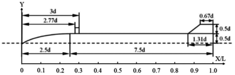
Model configuration and dimension.
The three-dimensional (3D) structured hexahedral grids are shown in Figure 2. The height of the first layer grid was

Computational grids: (a) AFF model and (b) AFF model with canards.
Computational grid parameters.

AFF: Air Force Modified Basic Finner Missile.
The coordinate system is shown in Figure 2. The canards and tails present a “−×” configuration initially. XY plane is the angle of attack plane. The missile spins about its longitudinal axis, which coincides with the x axis. Spin is realized through the grid motion in the inner area, and the bold line in Figure 2(a) is the interface. The positive y-axis direction is zero circumferential position. Spin rate and circumferential angle are positive when the projectile is experiencing a counterclockwise spin from the view of the base. Due to the canards interference, the aerodynamic characteristics of the tails with phase difference of
Validation of numerical method
The inflow conditions for grid independence study were Ma = 2.5,
Relative difference of aerodynamic coefficients of different grids.
AFF: Air Force Modified Basic Finner Missile.
Figure 3 presents the time-averaged aerodynamic coefficients of the AFF configuration at different Mach numbers

Variation of the time-averaged aerodynamic coefficients with Mach number: (a) lateral force and (b) yawing moment.
Results and discussion
Effect of canards on the time-averaged aerodynamic characteristics
The time-averaged aerodynamic coefficients of the two configurations are shown in Figure 4. Figure 4(a) presents the total normal force coefficient. The normal force coefficient increases first and then decreases as Mach number increases, reaching the extreme value in transonic condition. The total normal force of the canard configuration is larger due to the canards contribution. Figure 4(b) gives the total lateral force coefficient. For configuration without canards, the direction of the lateral force alters from negative to positive as Mach number increases, and the absolute value reaches the maximum in transonic condition. The lateral force of the canard configuration is always pointing to the negative z direction. In supersonic condition, the absolute value of the lateral force at

Time-averaged aerodynamic coefficients: (a) total normal force, (b) total lateral force, (c) body lateral force, (d) Fin 1 lateral force, (e) Fin 1 and Fin 2 lateral force, and (f) canard lateral force.
Figure 4(d) shows the Fin 1 lateral force. The Fin 1 lateral force is always positive and reaches the maximum magnitude in transonic condition. For the configuration without canard, the Fin 1 lateral force increases with angle of attack, and the variation tendency with Mach number is regular. For the configuration with canard, the Fin 1 lateral force increases, while it presents irregular variation with angle of attack, which is possibly affected by the wash flow induced by canards. In supersonic conditions, the amplification of lateral force decreases obviously with the increase in the Mach number, especially for the case at Ma = 2.5 and
Figure 5 gives the time-averaged distributed lateral force in the x-axis direction for the configurations with and without canards. The area between the curves and the x axis indicates the total lateral force coefficient. The lateral force around the canards and the tails is positive, while it is negative elsewhere. In the position between the canard trailing edge and the tail leading edge, the lateral force is negative and its absolute value increases obviously due to the interference of the canard on the surface flow. For the section between the tail leading edge and trailing edge: in subsonic condition, the lateral force changes from positive to negative; the canard interference increases the lateral force at

Time-averaged distributed lateral force: (a) Ma = 0.6,
Effect of canards on the transient aerodynamic characteristics
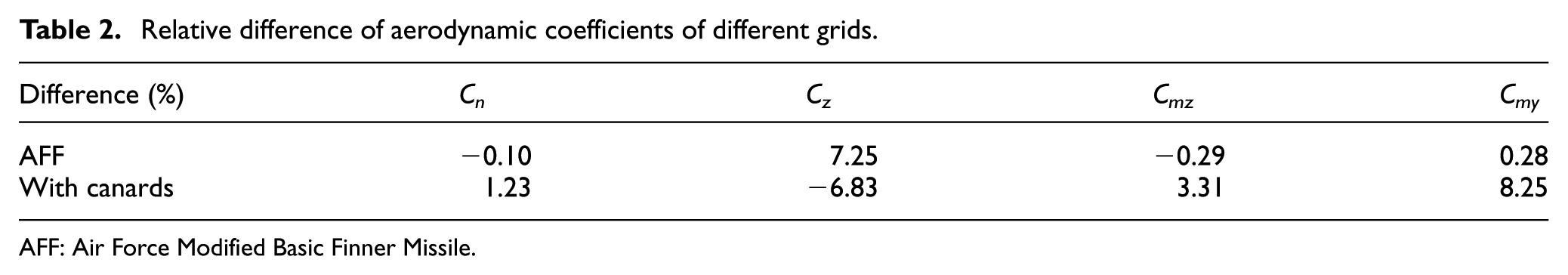
Figure 2(b) is the state of
Variation of total aerodynamic coefficients with rolling angle at Ma = 2.5: (a) normal force, without canards; (b) normal force, canards; (c) lateral force, without canards; and (d) lateral force, canards.
The body and Fin 1 lateral force of the two configurations are shown in Figures 7 and 8, respectively. As aforementioned, the Fin 1 lateral force is dominant compared with that of the Fin 2, thus only the results of the Fin 1 are given and analyzed in detail. In Figure 7, for the configuration with canards, the body lateral force presents a sharp oscillation and alters direction with rolling angle due to the canards interference. However, the body lateral force is always negative for the configuration without canards. It can be seen from Figure 8 that the canards interference on Fin 1 is relatively weak compared with that on the body. The canards interference is stronger in subsonic conditions than in supersonic conditions. Note that the curve of the body lateral force in subsonic condition has a phase lag of

Variation of body lateral force coefficients with rolling angle: (a) Ma = 0.6, without canards; (b) Ma = 0.6, canards; (c) Ma = 2.5, without canards; and (d) Ma = 2.5, canards.

Variation of Fin 1 lateral force coefficients with rolling angle at Ma = 2.5: (a) without canards and (b) canards.
Interference mechanism of canards on body lateral force
As mentioned previously, the time-averaged lateral force of symmetrical configuration is totally attributed to the Magnus effect. At rolling angles
The situations around the extreme value of the body lateral force coefficient curve (Figure 7) were chosen to analyze the interference of canards on body transient lateral force through flow field structures. Figure 9 shows the surface pressure coefficient contour and the cross-sectional vorticity magnitude of the configurations without and with canards, and the distributed body lateral force at Ma = 0.6,

Surface pressure contour and cross-sectional (x/L = 0.33, 0.48, 0.72, and 0.98) vorticity magnitude of configurations (a) without canards; (b) with canards; and (c) distributed body lateral force at Ma = 0.6,
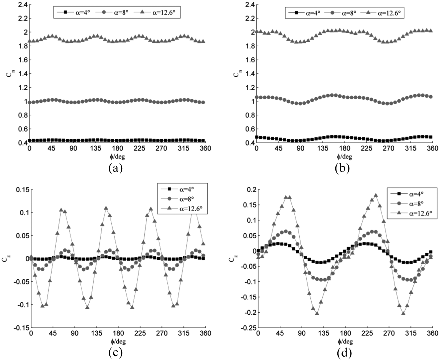
Figure 10 presents the pressure contour and streamlines of the configurations without and with canards, and the pressure difference between the right and the left bodies at x/L = 0.33, 0.48, and 0.72. The positions correspond to the cross sections in Figure 9. In Figure 10(a), for the configuration without canards, the spin rate of left-side body is against the cross-flow velocity. The cross-flow is resisted by the surface viscosity and adverse pressure gradient. Thus, the cross-flow velocity decreases and the pressure increases compared with the right side, leading to a pressure difference in the negative z direction. With the development of the cross-flow along the positive y direction, flow separation occurs earlier on the left-side body than on the right-side body, because the cross-flow cannot overcome the viscous force and the adverse pressure gradient. The right-side separation vortex stays near the surface and the cross-flow reattaches. For the cross section next to the canards, the surface pressure distribution is strong influenced by the canards. The flow separation and leeside separation vortex shift toward the negative z direction, and the low-pressure region on the right-side body decreases, leading to a positive z pressure difference; the windward surface is influenced by the flow over the canard and the high pressure shifts toward the positive z direction, resulting a negative z pressure difference around
Pressure contour and streamlines at different cross-sectional profiles, and the z direction pressure difference between the right- and the left-side bodies at Ma = 0.6,
Figure 11 shows the surface pressure coefficient contour and the cross-sectional vorticity magnitude of the configurations without and with canards, and the distributed body lateral force at Ma = 2.5,

Surface pressure contour and cross-sectional (x/L = 0.33, 0.48, 0.72, and 0.98) vorticity magnitude of configurations (a) without canards; (b) with canards; and (c) distributed body lateral force at Ma = 2.5,
Figure 12 presents the pressure contour and streamlines of the configurations without and with canards, and the pressure difference between the right and the left bodies at x/L = 0.33, 0.48, and 0.72. The different positions correspond to the cross sections in Figure 11. In Figure 12(a), for configuration with canards, the left-side canard leeward expansion wave increases the body leeward low-pressure region, leading to a positive z pressure difference; around

Pressure contour and streamlines at different cross-sectional profiles, and the z direction pressure difference between the right and the left-side bodies at Ma = 2.5,
Interference mechanism of canards on tail lateral force
The variations of Fin 1 lateral force with rolling angle for the configurations with and without canards are similar. To investigate the difference between the curves, subtracting the AFF Fin 1 lateral force coefficient (Figure 8(a)) from the Fin 1 lateral force coefficient of the canard configuration (Figure 8(b)) and then dividing by the maximum value of curve at the corresponding angle of attack in Figure 8(b), we obtain the contribution percentage of the canards on the Fin 1 lateral force coefficient at Ma = 0.6, as shown in Figure 13. Canards interference contributes to the positive time-averaged lateral force of Fin 1. Meanwhile, canards interference is strong when

Contribution of canards interference on the Fin 1 lateral force with rolling angle at Ma = 0.6.
The case for

Pressure coefficient distribution at midspan at Ma = 0.6,

Surface pressure contour and spatial streamlines around Fin 1 at Ma = 0.6,
Figure 16 shows the contribution percentage of the canards interference on the Fin 1 lateral force at Ma = 2.5. The contribution of the canards interference on the time-averaged lateral force of Fin 1 is positive at

Contribution of canards interference on the Fin 1 lateral force with rolling angle at Ma = 2.5.
The case for

Pressure coefficient distribution at midspan at Ma = 2.5: (a)
Figure 18 presents the Fin 1 surface pressure contour and the spatial streamlines for the configurations without and with canards at

Surface pressure contour and spatial streamlines around Fin 1 at Ma = 2.5 and
Conclusion
Based on the RANS equations, combining the dual-time stepping method and the
In subsonic conditions, flow over the canard root interferes with the body overflow, increasing the body boundary layer distortion at small angle of attack and the separation asymmetry at large angle of attack. The transient body lateral force alters direction with rolling angle while the time-averaged negative body lateral force doubles and becomes dominant. The canards interference has little effect on the force acting on body around the tails compared with the forebody case. The canards interference increases in the streamline curvature and the downwash effect on leeward tail increases, decreasing the negative lateral force of the tails. Compared with the configuration without canards, the time-averaged tail lateral force increases and the variation percentage of tail transient lateral force reaches 50% at
In supersonic conditions, the shock and expansion waves on the canard windward and leeward interfere with the body overflow, increasing the distortion of the flow field about angle of attack plane; the leeward separation vortices and the secondary vortices contribute to an additional small body lateral force locally; asymmetrical flow separation always contributes to a negative body lateral force with considerable magnitude. The canards interference on the body around the tails cannot be neglected and the time-averaged body lateral force is smaller than that in subsonic conditions. Due to the change in the direction of wash flow as angle of attack increases, the canards contribution on the tail lateral force alters from positive to negative. At large angle of attack, flow over the canards root interferes with the leeward separation vortex and the wash flow energy decreases. The absolute variation percentage of the tail transient lateral force stays within 20% and is smaller than that in subsonic conditions.
In short, this research is concentrated on the flow mechanism of the lateral force of an axisymmetric spinning projectile with fixed canards. For asymmetric configurations with deflected canards and canted tails, and projectile experiencing complicated pitching and coning motions, the corresponding flow mechanisms need further studies.
Footnotes
Appendix 1
Handling Editor: Ruey-Jen Yang
Declaration of conflicting interests
The author(s) declared no potential conflicts of interest with respect to the research, authorship, and/or publication of this article.
Funding
The author(s) disclosed receipt of the following financial support for the research, authorship, and/or publication of this article: This research was supported by the National Natural Science Foundation of China (grant number 11372040).