
Abstract
To achieve more accurate simulation and control in the use of the manipulator, it is necessary to establish an accurate dynamic model of the redundant manipulator. The research of this article focuses on the dynamic parameter identification method of the redundant manipulator. In the study, the spinor theory is applied to the Newton–Euler dynamic equation, the Coulomb + viscous friction model is adopted, and the minimum parameter set is obtained by linearization derivation. The parameter identification of the manipulator is realized using the method of offline identification of the measured current, and the coefficient of the excitation trajectory is optimized using the nonlinear optimization function. Finally, the parameter set with high accuracy is obtained, and the motion trajectory of each joint can be obtained. The scheme has high accuracy and can meet the needs of practical application. To verify the accuracy and reliability of this method, we have carried out experiments on a service robot “Walker” and obtained the desired results.
Keywords
Introduction
The identification of the dynamic parameters of the manipulator mainly involves the methods of estimating structural, inertial, and friction parameters, which are the basis of the research on the manipulator. In general, structural parameters can be obtained by kinematic calibration, while dynamic parameters need to be estimated by identification method. 1 –3 At the same time, due to changes in the external working environment, the length of the working manipulator and the difference in the clamping equipment at the end of the working manipulator will affect the dynamic characteristics of the manipulator. 4,5 To obtain the required torque calculation accuracy and achieve high-precision control based on the dynamics model without increasing the complexity of the model, it is very important to study the parameter identification of redundant manipulator.
From the perspective of determining dynamic parameters, existing research on the identification of dynamic parameters is divided into online identification and offline identification, while in terms of torque measurement, it is divided into current measurement identification and torque measurement identification. 6 –8 Online identification is to find out the parameter values in the mathematical model of the system from the online measured data so that the predicted dynamic response is consistent with the response of the actual system. Jubien et al., 9 Gaz and De Luca, 10,11 Burdet and Codourey, 12 and Honegger et al. 13 successfully identified the parameters of the manipulator by online identification. However, Jiang et al. 14 found that the neural network could also be effectively used for online identification of nonlinear systems. Ghannadi et al. 15 applied Dynamic parameter identification (DPI) to parameter identification of robots with actuator gaps. The offline identification is different from the calculation of parameter value based on the online measured data. The parameter of the manipulator can be identified mainly through physical experimental methods, computer-aided design methods, and trajectory motion methods. 16 Tourassis and Neuman 17 used the vibration response of the connecting rod to determine the inertial parameters through physical experiments. Brown and McPhee 18 used friction models to identify the parameters. Guegan et al. 19 and Vivas et al. 20 identified the parameters of the manipulator by planning its trajectory. The linear relationship between the driving torque of the motor and the current is the basis of current measurement identification. Gautier and Poignet 21 used Kalman filtering and least-squares methods to identify the parameters of the manipulator when using the current data to identify the parameters and achieved satisfactory results. The collection of force sensing information of the robot is the key to force measurement identification. Liu et al. 22 proposed to identify inertial parameters based on force measurement and obtained the dynamic parameters of the manipulator through calculation.
Parameter identification of robots, as one of the key problems in the accurate modeling, control, and simulation of robots, has attracted extensive attention from scholars at home and abroad. With the expansion of the application scope of robots, higher requirements are put forward for the control accuracy of robots. More accurate parameter identification methods are an important basis for improving control accuracy. However, existing parameter identification methods still have shortcomings such as the inability to simulate complex influencing factors and low identification accuracy. 1,7,23 In this article, the spin theory is introduced on the basis of the Newton–Euler dynamics equation. The minimum parameter set is obtained by linearization derivation taking into account the friction term. The excitation trajectory is designed in the basic form of Fourier series fully considering the limit and velocity of the joint. The nonlinear optimization function 24 is used to optimize the coefficients of the excitation trajectory to minimize the condition number of the observation matrix and obtain the available joint trajectories. Finally, the correctness and effectiveness of the proposed method are verified on an actual robot.
Parameter identification principle of redundant manipulator
Dynamic model of redundant manipulator considering friction
The dynamic model in this article is based on the Newton–Euler equation. Since the redundant manipulator studied has only one rotating joint, it can be simplified to exclude friction and external force terms

where
In the actual control of a manipulator, friction is a key factor affecting the control accuracy. Therefore, the identification of friction parameters is very important in parameter identification. Further extended by equation (1), dynamic equation considering the existence of the friction term is

where

where fc is the Coulomb friction constant, fv is the viscous friction constant, and
Set of minimum inertia parameters
In the identification of the dynamic parameters of the manipulator, the structural parameters and inertial parameters of the joints need to be considered while considering the friction model. The simple configuration of the joint link is shown in Figure 1.

Simplified diagram of joint parameters.
As can be seen from the figure, the parameters of each joint link k include mass mk, the center of mass position rk, the first moment of inertia lk, and the inertia tensor Lk in the link coordinate system. Thus, we obtain

And according to Huygens–Steiner theorem, we can get

where Ik is the centroid inertia tensor and
According to existing studies, by combining and transforming parameters, equation (2) can be linearized as

where dynamic parameters can be identified through linear regression, so it can be written as

where Hs is a regression matrix composed of the superposition of the joint pose (joint angle, joint speed, and joint angular acceleration) of the manipulator, which is expressed as

And ω is a matrix composed of the measured moments corresponding to these joint poses, and it is expressed as

The torque sensor at the joint of the robot arm can be generally read directly. In the absence of torque sensor, the joint motor current data can be used. Among them, δ is the dynamic parameter set of the link of the robot arm, and thus, the parameter set of a robot arm system with N links can be expressed as

For each k link of the redundant manipulator, the parameter set δ consists of mass, inertia tensor, first moment of inertia, and friction parameters, and it is specifically expressed as

The link parameter set

In practical calculation, since some parameters have no effect on robot dynamics, other parameters show linear proportional relationship, matrix HS is listed as zero, correlation is listed as linear, so HS is a singular matrix with multiple solutions. To solve this problem, the parameters are usually eliminated and recombined into the basic parameter vector

where

where W can be obtained by eliminating the correlation column of HS. At this time, the regression problem can be expressed as

The optimal solution of the above equation is

At this time,
Experimental verification
Introduction of experiment hardware
Walker is a humanoid robot that works with 36 high-performance servo joints and a force feedback system. The dual arms are two seven-degrees-of-freedom redundant manipulator arms. This robot was used for the experiment in this study. The physical image of the walker and the structure of the manipulator are shown in Figure 2.
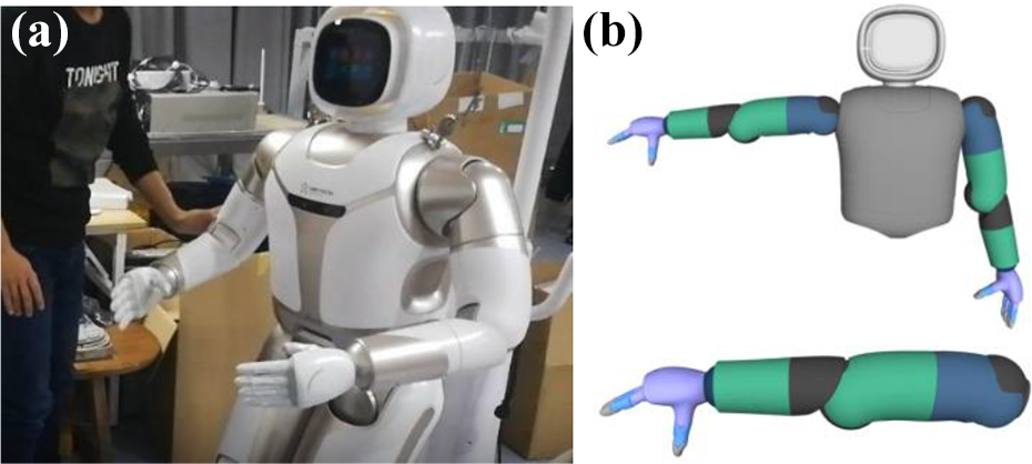
(a) Physical picture of the Walker and (b) structure of the manipulator.
Walker’s joint drive was realized by servo steering gear. Large torque, small size, and high-precision servo steering gear are the keys to robot drive technology. Walker’s servo steering gear adopted an integrated drive unit, which was composed of a frameless torque motor, a drive controller, a precision harmonic reducer, and a dual encoder. Three control modes of position mode, speed mode, and torque mode were supported to meet the requirements of joint control.
According to the configuration of the right arm of the Walker manipulator, the link coordinate system of the right arm with seven-degrees-of-freedom was established to determine the series relationship between the seven links and the definition of the link coordinate system. Link coordinate system of Walker is shown in Figure 3.

Link coordinate system of Walker.
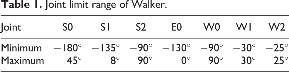
Each joint of the right arm of the Walker manipulator had a certain joint limit. The first four joints of the manipulator were mainly used for adjusting the end position and planning the movement trajectory, which was similar to the degree of freedom of human arm, and they had a relatively small range of movement. It was large, and there was only one direction of rotation after joint 4 was at the zero position, and the last three joints were mainly used for posture adjustment at the end of the manipulator, which was similar to the degree of freedom of human arm. And they had a small range of movement. Joint limit range of Walker is shown in Table 1.
Joint limit range of Walker.
Design and optimization of excitation trajectory
The design of excitation trajectory is very important in the parameter identification of manipulator. In the process of excitation trajectory, the dynamic parameters of the manipulator should be fully simulated, and the influence of noise on the measurement should be minimized, so as to only rapidly and accurately estimate the parameters but also ensure the accuracy of identification. In the process of the excitation trajectory, the velocity constraint and acceleration constraint in the joint motion should also be fully considered in the design to ensure that the sudden change of the joint velocity and acceleration in the joint motion is as small as possible. Many scholars have carried out extensive research on it. The excitation trajectory used for parameter identification in this article is based on the basic form of periodic Fourier series, which is specifically shown as

where
The value of

where
The coefficient optimization of Fourier series was solved by the nonlinear constrained optimization function fmincon in MATLAB, and the iterative optimization was carried out by setting the initial angle of the joint, range of angle, angular velocity, and angular acceleration in the joint motion. For the seven-degrees-of-freedom manipulator, the condition number of the W matrix is generally optimized to less than 100 and converges at the same time. The number of iterations in this optimization was 164, and the condition number of the final optimized W matrix was 75.5086. The change of the condition number in the optimization process is shown in Figure 4. The values of Fourier series coefficients obtained by nonlinear function optimization

Change of condition number in the process of optimizing Fourier series coefficients.
Fourier series coefficients obtained by optimization.

Trajectory tracking and motion data sampling
According to the Fourier series coefficients obtained, the value of
In the process of joint motion, the data were sampled at the time interval of 10 ms, and the data contents were time point, joint angle, joint angular velocity, joint angular acceleration, and joint torque. The general manipulator joint can read the joint torque data directly through the torque sensor. If there is no sensor, the rigid joint can read the motor current value and identify the parameters of the manipulator by measuring the current. However, the joint angular velocity data cannot be read directly but is generally calculated by the differential of joint angular velocity.
Parameter estimation and inverse dynamics verification
According to the collected data, the dynamic parameters of the manipulator were identified offline. Firstly, the data were preliminarily processed by MATLAB, the data points were improved by one-dimensional data interpolation to reduce the time node, and then, the moving average filter was used to smooth the data and remove noise data. According to the data collection, we filtered on the basis of a filter several times, until we obtained the desired data. The joint torque data measured by the experiment are shown in Figure 5, in which green line is for the original data, blue line for primary filtering data, and red line for secondary filtering data. In the actual data processing, since the manipulator starts to move at a low speed and the data collected in the early stage fluctuated, the data in the first 20 s were eliminated for research.

Joint torque value after data processing: (a) Joint 1, (b) joint 2, (c) joint 3, (d) joint 4, (e) joint 5, (f) joint 6, and (g) joint 7.
In the process of identification, equation (7) can be obtained by linearizing the dynamic model according to the previous theoretical basis, and the specific parameters are identified and deduced to obtain the final identification result

The above equation is a further derivation of the calculation of the minimum parameter set according to the requirements of the actual programming calculation. According to the above formula, the minimum parameter set of redundant manipulator in Coulomb + viscous friction model can be obtained by programming calculation. In this experiment, the process was realized by MATLAB, and it can also be realized by other programming software. At this time, the inverse dynamics verification was carried out with the same original data, and the calculated torque value

Inverse dynamic verification of torque values of each joint: (a) Joint 1, (b) joint 2, (c) joint 3, (d) joint 4, (e) joint 5, (f) joint 6, and (g) joint 7.
It can be seen from the figure that the red line basically fluctuated around 0, that is, the calculated torque value of each joint was basically consistent with the actual torque value after the noise was removed, but in the joint motion, the error between the actual value and the calculated value near the reverse point of the joint torque was larger, which was consistent with the previous analysis. At the same time, since joint 7 was an end joint, the minimum joint load was only within ±0.4 N/m. The error between the joint torque calculated by identification and the actual torque was large, but it had little influence in the actual work, which was consistent with the previous analysis. In terms of the dynamic parameter identification of the manipulator, due to the large fluctuation of the acceleration signal, the identification of inertia parameters will generally be affected by noise signal, reverse friction, and other factors, which will lead to the error near the reverse point of joint torque. After many repeated experiments with the same experimental parameters and environment, stable and definite results were obtained. The parameter set identified by linearizing the dynamic model generally is accurate and can meet the needs of actual control. Experimental results show that the proposed scheme is superior to the traditional online parameter identification and current measurement schemes, and significantly improves the robustness and parameter learning performance of the proposed method.
Conclusions
In this article, the whole process of dynamic parameter identification of redundant manipulator was studied. Based on the Newton–Euler dynamic equation, the spinor theory was introduced, the Coulomb + viscous friction model was adopted, and the minimum parameter set was further deduced through linearization. In addition, the parameters of the manipulator were identified by the offline identification method of measurement current, and the excitation trajectory was designed in the basic form of Fourier series while considering the joint limit and joint velocity. The nonlinear optimization function was used to minimize the condition number of the observation matrix as the coefficient of the objective optimization trajectory, thus obtaining the available joint trajectories. Finally, the correctness and effectiveness of the method were verified on the actual robot Walker. The proposed scheme is very suitable for compound control of robot system and other robot control applications. 25
Footnotes
Declaration of conflicting interests
The author(s) declared no potential conflicts of interest with respect to the research, authorship, and/or publication of this article.
Funding
The author(s) disclosed receipt of the following financial support for the research, authorship, and/or publication of this article: This work was supported by the National Key R&D Program of China [Grant No. 2018YFB1306905].