
Abstract
This study performed a comparison of the stiffness and natural frequency of a redundant parallel conveyor and its nonredundant counterpart. A 3-degree-of-freedom parallel conveyor that is used for the pretreatment and electrocoating of car bodies is simplified into a planar redundant parallel manipulator to derive the kinematic and dynamic models using a symmetrical architecture. The stiffness model is derived with a matrix structural method, and the dynamic model is obtained. The position and orientation workspace is analyzed, and the conditioning performances of the redundant manipulator and the nonredundant counterpart are assessed. Next, we contrast the stiffness and natural frequency of the redundant parallel manipulator with its nonredundant counterpart. The simulation results indicate that the redundant parallel manipulator has a greater stiffness and a higher natural frequency in the workspace. The redundant parallel manipulator is a preferred choice for developing this parallel conveyor.
Introduction
Electrocoating of a vehicle body is a necessary process in the production of the vehicle body. Before the actual coating operation, the pretreatment process is important and complex, and it involves multiple physicochemical processing operations including phosphatizing, passivation, and activation plus the associated rinsing operations. All treatments need to be carried out in the handing container at the corresponding treatment station, and the pretreatment must be finished before the actual coating operation. Therefore, a conveyor is needed between each treatment station to transport the vehicle body. 1
With increases in the complexity of the vehicle body geometry, the process of pretreatment has also been continuously improved. As far as the conveyor is concerned, the conveyor can be mainly classified into two categories: the conventional conveyors and the modern conveyors. Conventional conveyors comprise a pendulum conveyor, 2 overhead power and free conveyor, 3 and auto-motor-hoist. 4 Modern conveyors include Vario-Shuttle 5 and RoDip conveyors. 6 Recently, Clifford et al. 7 put forward the new transportation mode of pretreatment production line. The air pocket problem on the surface of the vehicle body is difficult to deal with in the conventional conveyors. The drawback is overcome by modern conveyors that have a conveyor technology that rotates the vehicle bodies when they go through the electrophoresis container.
These benefits apply especially to paint shops working at lower capacities. Thus, they have been added to many newer automobile plants for high-quality painting. While Vario-Shuttle and RoDip conveyors are effectively used inside car manufacturing facilities, the conveyors exhibit certain drawbacks. Cantilever beams are used in both conveyor systems. The lack of static and dynamic stiffness of cantilever beam architecture results in a deformation of the structure. The conveyors’ load-carrying ability is so minimal that they are only able to move little vehicles for pretreating and electrocoating. For example, two Vario-Shuttle systems are used to carry a heavy car for pretreating and electrocoating 1 Due to the high stiffness of parallel mechanisms, conveyors with a parallel mechanism have a high load-carrying capacity. 8 A planar parallel mechanism is used to control the motion of an object in a plane. For planar parallel manipulators, all the trajectories of all points are in one plane. The planar parallel manipulator has a simple structure, and the actuator can be fixed on the base to reduce the inertia of the moving body. In addition, there is the advantage of general parallel mechanisms. Thus, many researchers have recommended planar parallel mechanisms.9,10 If planar parallel mechanisms are used to develop conveyors, the conveyors will have better performance. The parallel mechanism also has some disadvantages such as smaller workspaces and many singular configurations.11,12 However, these disadvantages of the parallel mechanism can be overcome by redundancy.13,14 Thus, conveyors with redundant parallel mechanisms have great potential in paint shops.15,16
The stiffness and natural frequency are significant considerations for a conveyor in a painting production line because higher stiffness and natural frequency mean higher load-carrying capacity. Different methods have been used to investigate the stiffness and dynamic performances of parallel manipulators. 17 Preferably, this task can be completed using business-geared finite element analysis (FEA) software. Nevertheless, the FEA model needs to be remeshed on an ongoing basis, and this ends up being a monotonous and laborious procedure. 18 Also, it is difficult to deal with the joint effect on the dynamic performance, as well as the position and structural parameter effects. Zhao et al. 19 employed an elastodynamic approach to examine the intense qualities of a redundantly actuated parallel manipulator. Fattah et al. 20 used the finite element method to form a model of the flexible links. The natural orthogonal complement is used in this model for elimination of the constraint forces and deriving the minimum number of motion equations. The authors are not aware of any prior studies contrasting the stiffness and dynamic performance of the redundant parallel conveyor and its nonredundant counterpart. This was the main motivation of our study.
This article assesses the stiffness and natural frequency of the redundant parallel conveyor for pretreating and electrocoating of vehicle bodies. In addition, the stiffness and natural frequency of the redundant parallel conveyor and its nonredundant counterpart are compared. This article is organized as follows: section “Introduction” introduces the conveyor and the problems arising in its design. Section “Structure description and kinematics” gives the kinematics of the redundant parallel conveyor and its nonredundant counterpart. Section “Stiffness model” addresses the stiffness modeling. Section “Natural frequency” deals with the natural frequency. Section “Numerical simulation” gives a numerical simulation using the results of the earlier sections. Finally, some concluding remarks are presented in section “Conclusion.”
Structure description and kinematics
Structure description
In pretreatment processes and electrophoresis of a car body, the conveyor moves the car body obliquely downward into the electrophoresis container until the car body completely enters the electrophoresis container. Meanwhile, the car body is horizontally adjusted. Then, the conveyor carries the car body out of the electrophoresis container and makes the car body horizontal again. During the whole process, the conveyor moves along its tracks. Figure 1 shows that the conveyor system is composed of the conveyor and the track fixed on the frame. The conveyor can move along the track, and the conveyor is composed of a hoist frame and two parallel manipulators, which include a moving platform and four kinematic chains. The parallel manipulator is redundantly actuated because the three kinematic chains are sufficient for the moving platform to possess 2 translational degrees of freedom (DOFs) and 1 rotational DOF. As the conveyor moves the vehicle bodies through the manufacturing line, the parallel manipulator must possess great stiffness and natural frequency. Therefore, actuation redundancy is incorporated in the parallel manipulator to increase the stiffness and natural frequency. The moving beam is lifted via a hoist. A vehicle shell holding the vehicle body is set on the hoist. Depending on the various kinds of vehicles and how much they weigh, the vehicle frame can be substituted with additional vehicle frames with differing dimensions. Thus, the parallel conveyor is appropriate for various kinds of vehicles and different vehicle weights.
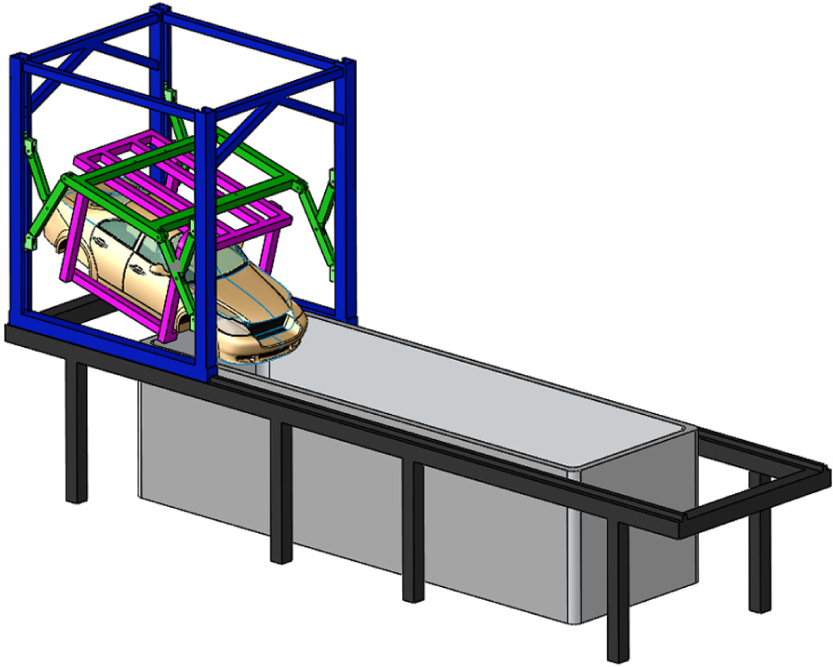
A 3-DOF parallel conveyor.
Inverse kinematics
Figure 1 demonstrates that the parallel conveyor is evenly shaped, and the two parallel manipulators possess identical forms and motion. Since the car frame can be of very high stiffness relative to the parallel manipulators, the stiffness and dynamic performance of the parallel manipulators with the lowest stiffness in the whole conveyor reflect the stiffness and dynamic performance of the entire conveyor. In kinematic and dynamic representation, just one parallel manipulator is examined. The redundantly actuated parallel manipulator is composed of a moving platform E1E2, a gantry frame, and four constant length links, as shown in Figure 2. Sliders C1 and C2 are motivated by two actuators and propel links C1D1 and C2D2. Links B1E1 and B2E2 have one base linked with sliders B1 and B2, and the opposite base is attached to the moving platform E1E2, driven by sliders B1 and B2.

Kinematic model of a parallel manipulator.
A global coordinate system O–YZ is joined to the middle point O of the gantry frame. The Z-axis is upright and the Y-axis indicates A2. A moving coordinate system O′–X′Y′ is affixed to the center point O′ of the moving platform, as demonstrated in Figure 2. The equation
From Figure 2, the following equations can be obtained


where
Using equations (1) and (2), the reciprocal results of the kinematics can be expressed as
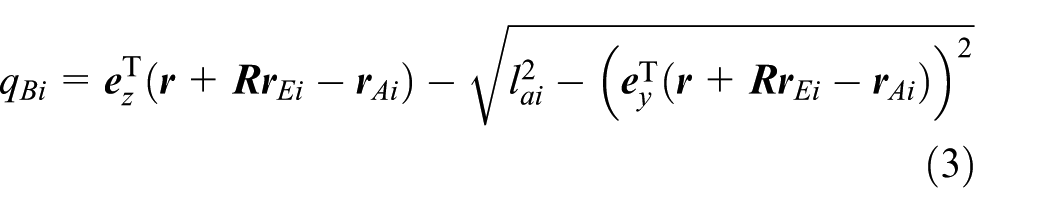
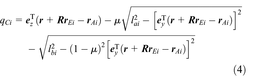
where
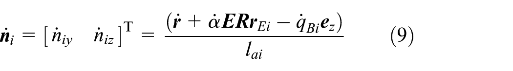
Therefore, the unit vectors of links


Using the derivatives of equations (1) and (2) in regard to time leads to


where
Using the derivatives of equations (7) and (8) in regard to time leads to

Using the dot product with


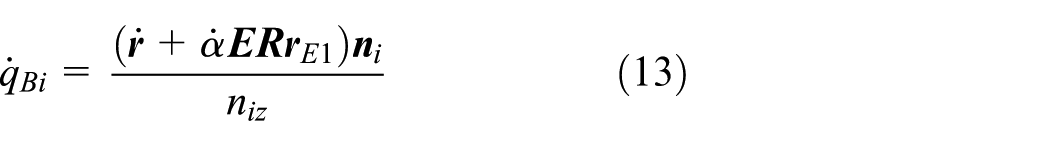
Using equations (9) and (10),

Jacobian matrix
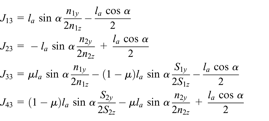
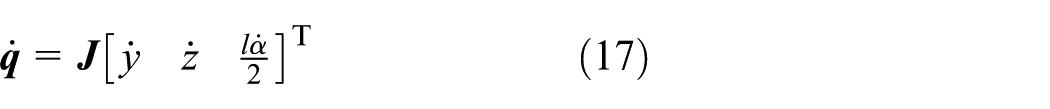
Generally, the Jacobian matrix describes the mapping between the joint velocities and the end-effector velocities. Using the time derivative of equations (3) and (4) leads to

where

where
It is understood that velocity has a dimension. As the output velocity of the manipulator incorporates the linear and angular velocities, the condition number of the Jacobian matrix, typically utilized to assess agility, has no precise physical meaning. The angular and linear velocity dimensions should be written uniformly to solve this problem.
It is believed that the moving platform shifts around joint point
in which

For the nonredundant parallel manipulator, link

Stiffness model
Stiffness is a mechanical quality that illustrates the actions of a formation beneath the static force in light of elastic deflection. There are about three kinds of stiffness modeling methods for manipulators: the virtual joint modeling method, the FEA method, and the matrix structural analysis method. The matrix structural analysis method can reduce the amount of calculation and save time. In addition, explicit analytical expressions can be obtained.18,21 In this article, the matrix structural analysis is utilized to produce the stiffness model.
Based on the structural parameters of the parallel manipulator, the element stiffness matrix in the element coordinate system can be derived. The element stiffness matrix in the global coordinate system can be transformed from the element stiffness matrix in the element coordinate system. Then, elements are performed to constrain DOF according to the connection forms. Finally, the global stiffness matrix of the complete element assemblage is effectively obtained from the stiffness matrix of individual elements using the element integration method. 22
Stiffness element
The general spatial beam element contains two nodes (i, j). Each node has 6 DOFs, and there are six generalized forces and displacements in different directions. In the element coordinate system, the external force

where
Based on Hooke’s law, the stiffness equation of elements in the element coordinate system can be expressed as

where
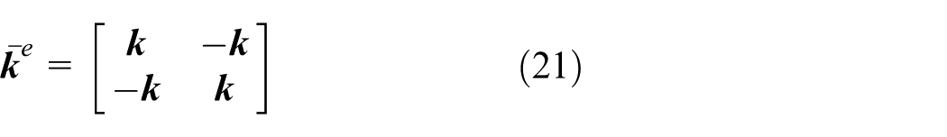
where

and the nonzero elements are k11 = EA/L, k22 = 12EIz/L
3
, k33 = 12EIy, k44 = GJ/L, k55 = 4EIy/L, k66 = 4EIz/L, k35 = k53 = −6EIy/L
2
, and k26 = k62 = 6EIz/L. Here, L is the length of the spatial link element, A is the cross-sectional area, and
The force vectors and displacements of each node in the global coordinate system can be written as
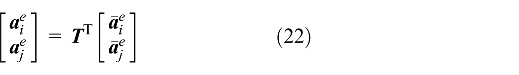
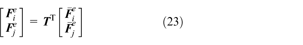
where
Through the replacement of equations (22) and (23) in equation (20), the connection among force vectors and node displacements in the global coordinate system can be expressed as

in which
Stiffness integration
There are three forms of connection (joint connection, rigid connection, and insertion end) between two elements. If the two elements are relatively stationary, a rigid connection can be achieved using an integration method. If there is relative motion between two elements, a joint connection can be executed by DOF condensation. A clamp node of elements can be executed by an insertion process. The integration process of the overall stiffness matrix is same as that of the matrix structural analysis.
Assuming that the whole manipulator has n nodes, and the ith element has l nodes numbered
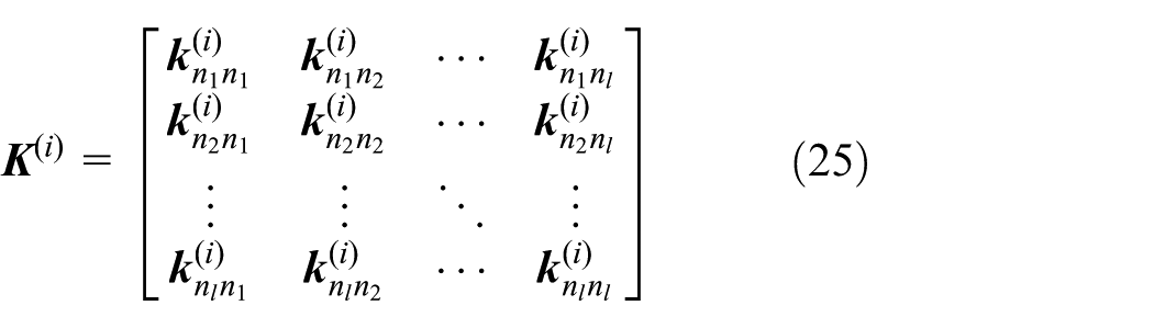
where
Similarly, the number of nodes for the overall manipulator is n, and the entire stiffness matrix can be expressed as follows
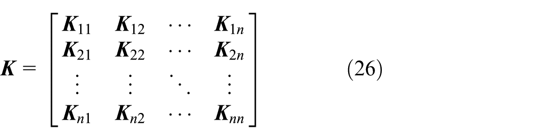
where
Let
where
For the whole manipulator, the stiffness equation can be expressed as

Natural frequency
In the pretreating and electrocoating processes of car bodies, the car body descends into and then rises slowly out of the electrophoresis container. The dynamic characteristics of the parallel conveyor have an important effect on the quality of the pretreating and electrocoating of car bodies.
The computation of natural frequency is important in engineering and is routinely performed in industry. This is typically performed during the design process of a mechanical structure to identify resonance frequencies (i.e. natural frequency). Indeed, resonance vibrations can cause a structure to wear out unreasonably fast or even fail due to fatigue. Increasing the natural frequency allows mechanisms to run at higher speed and more smoothly. For complex parallel mechanisms, natural frequencies are difficult to obtain by simple calculation, so the natural frequency needs to be analyzed and calculated accurately.
According to Hamilton’s principle,
23
the element mass matrix

where
Based on equations (26) and (29), the dynamic model of the manipulator can be expressed by

where
The damping has little impact on the natural frequency, and it is reasonable to neglect it. Thus, free vibration is used to determine the natural frequency of the parallel manipulator. The dynamical equation of free vibration without damping can be expressed as

The general solution of equation (31) can be expressed as

where
Substituting equation (32) into equation (31) leads to

Since

where
Let

where
It is assumed that
Thus, the natural frequency and vibration model of the system can be expressed as

where
Numerical simulation
Workspace and dexterity
The workspace of the manipulator consists of an orientation (pose) workspace and position workspace. In this section, only the position workspace is considered at first and then the minimum and maximum values of the orientation workspace in the position workspace are calculated. The position workspace of the redundant planar parallel mechanism is an area of the plane. It can be determined by the reachable space of point
In Chen et al.,
16
the geometrical and inertial parameters of the manipulator are optimized by considering energy consumption, the maximum dynamic load carrying, and the conditioning performance. These parameters are used in this article:

Position workspace of the parallel manipulator.
The position workspace is uniform in regard to the Z-axis because of the symmetry of the redundant parallel mechanism. In addition, the minimum and maximum values of the orientation workspace are shown in Figure 4. The orientation workspace is centrosymmetric with respect to the point

Orientation workspace of a parallel conveyor.
In the design process of the manipulator, the dexterity of the manipulator needs to be considered. The condition number of the Jacobian matrix is typically utilized to evaluate the agility of a manipulator. Therefore, the condition number of the Jacobian matrix is considered in this study. In the production line, the moving platform moves from the
Figure 5 shows that the condition number varies between 0 and 60 in the workspace for

Condition number for nonredundant conveyor at different orientations.
Figure 6 shows that the condition number varies between 0 and 11 in the workspace for

Condition number for redundant conveyor at different orientations.
Figure 7 reveals the condition number of the Jacobian matrix in the workspace. Obviously, the condition number of the redundant manipulator is lower than that of its nonredundant counterpart. The condition number can range from 1 to ∞ for a parallel manipulator. When the condition number is 1, the manipulator’s agility is optimal. Thus, the redundant manipulator has better dexterity and operating performance. When the Y coordinate decreases, the difference in the condition number between the redundant manipulator and its nonredundant counterpart increases. In some regions of the workspace, the condition number of the Jacobian matrix of the nonredundant manipulator is much greater than that of the redundant manipulator. The dexterity of the redundant manipulator is better than that of its nonredundant counterpart.

Condition number of the Jacobian matrix.
Stiffness distribution
The static stiffness and natural frequency can significantly affect working performance. Therefore, they should be considered in the mechanism configuration at the design stage. The modeling approach shown in section “Stiffness model” was utilized to produce the stiffness representation of the parallel conveyor, which was streamlined into a mechanical system made up of spatial beam components (Figure 8). The parallel conveyor included 15 elements and 13 nodes.

Nodes and elements of a parallel conveyor.
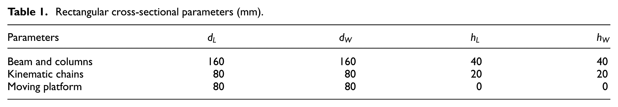
The elastic modulus is 210 GPa, and the Poisson ratio is 0.3. The cross sections of four kinematic chains and a platform are a rectangle, as shown in Figure 9. The cross-sectional parameters of four kinematic chains and a moving platform are shown in Table 1.

Cross section of links.
Rectangular cross-sectional parameters (mm).
The Y-direction position, Z-direction position, and X-direction rotation stiffness of the parallel manipulator are reproduced using the kinematic example of the parallel manipulator, as shown in Figure 10. From Figure 10, the Y-direction position, Z-direction position, and X-direction rotation stiffness of the redundant parallel manipulator are greater compared to the nonredundant counterpart. The stiffness dispersions of the redundant parallel manipulator are identical in regard to the Y-axis due to the mirroring structure of the manipulator. When the Y coordinate decreases in the workspace, the Y-direction position and X-direction rotation stiffness of the nonredundant counterpart decrease. In some regions of the workspace, the Y-direction position, Z-direction position, and X-direction rotation stiffness of the nonredundant parallel manipulator are low. The reason is that the nonredundant parallel manipulator has no additional link compared to the redundant one and its architecture is asymmetrical.

Stiffness distribution of the parallel conveyor: (a) position stiffness in the Y-axis direction, (b) position stiffness in the Z-axis direction, and (c) rotation stiffness around the X-axis direction.
Natural frequency
Figure 11 reveals the natural frequency of the redundant parallel manipulator and the nonredundant counterpart. The natural frequencies of the first three orders of the redundant manipulator were higher than those of its nonredundant counterpart. The third-order natural frequency of the redundant manipulator improved quite a bit, and each natural frequency of the redundant manipulator became symmetrical with respect to the Z-axis. The dynamic performance of the redundant parallel counterpart improved compared with the nonredundant parallel manipulator by introducing an additional link. Because the low-order natural frequencies are low, the amplitude is high when vibration occurs at the natural frequencies, and it has an important impact on the stability of the mechanism. Thus, low-order natural frequencies can reflect the dynamic performances of a manipulator. The control of a redundant parallel manipulator is more complex than its nonredundant counterpart. However, researchers have proposed some control methods that are not challenging. 10 Based on the analysis of stiffness and natural frequency, and considering the control problem and internal force optimization of the redundant parallel manipulator, it is more suitable to use the redundant parallel manipulator to develop this conveyor for pretreating and electrocoating of car bodies.
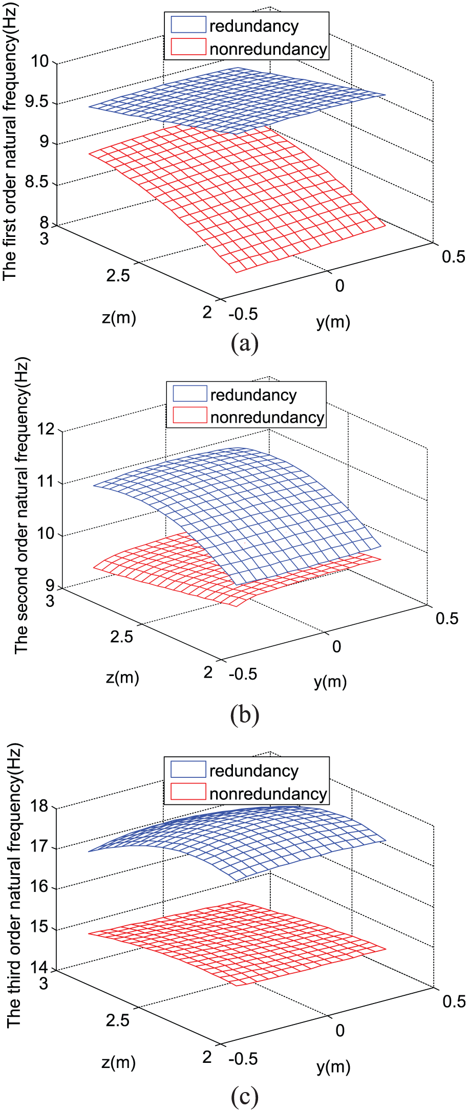
Natural frequency of the parallel conveyor: (a) first-order natural frequency, (b) second-order natural frequency, and (c) third-order natural frequency.
Conclusion
The stiffness and natural frequency of a parallel conveyor for pretreating and electrocoating of vehicle bodies were analyzed in this study. The stiffness and natural frequency of the redundant parallel manipulator were compared with those of the nonredundant manipulator. The condition number of the redundant manipulator was lower than that of its nonredundant counterpart, and the redundant parallel manipulator was better in dexterity. For the redundant manipulator, the Y-direction position stiffness, Z-direction position stiffness, and X-direction rotation stiffness were all higher than those of the nonredundant counterpart, and the natural frequency at each order was higher than that of the nonredundant counterpart. Since the redundant manipulator had better dexterity and static and dynamic performances than its nonredundant counterpart, it is more feasible to use the redundant manipulator to develop this conveyor for pretreating and electrocoating of vehicle bodies.
Footnotes
Handling Editor: Yangmin Li
Declaration of conflicting interests
The author(s) declared no potential conflicts of interest with respect to the research, authorship, and/or publication of this article.
Funding
The author(s) disclosed receipt of the following financial support for the research, authorship, and/or publication of this article: This work was supported by the National Natural Science Foundation of China (grant nos 51622505 and 51575307), the Science and Technology Major Project-Advanced NC Machine Tools & Basic Manufacturing Equipments (2016ZX04004004), and Top-Notch Young Talents Program of China.