
Abstract
Cable-driven parallel robots comprise driven actuators that allow controlled cables to act in parallel on an end-effector. Such a robotic system has a potentially large reachable workspace, large load capacity, high payload-to-weight ratio, high reconfigurability, and low inertia, relative to rigid link serial and parallel robots. In this work, a multi-degrees-of-freedom cable-suspended robot that can carry out pick-and-place tasks in large workspaces with heavy loads is designed. The proposed cable-driven parallel robot is composed of a rigid frame and an end-effector that is suspended from eight cables—four upper cables and four lower cables. The lengths of the cables are computed from the given positions of the suspended end-effector using a kinematic model. However, most multi-cable-driven robots suffer from interference among the cables, requiring a complex control methodology to find a target goal. Owing to this issue with cable-driven parallel robots, the whole control structure decomposes positioning control missions and allocates them into upper level and lower level. The upper level control is responsible for tracking the suspended end-effector to the target region. The lower level control makes fine positional modifications. Experimental results reveal that the hybrid control mode notably improves positioning performance. The wide variety of issues that are considered in this work apply to aerostats, towing cranes, locomotion interfaces, and large-scale manufacturing that require cable-driven parallel robots.
Keywords
Introduction
Cable-actuated robots are extensively used in aerostats, towing crane systems, elevators, and other devices. Cable-driven parallel robots consist of driven actuators that enable controlled cables to act in parallel on an end-effector. 1 Such a robotic system has a potentially large reachable workspace, large load capacity, high payload-to-weight ratio, high reconfigurability, and low inertia, in comparison to rigid-link serial and parallel robots. Nevertheless, these advantages may be outweighed by the fact that the cables that are used in these systems are relatively flexible and provide only a tensile and not a compressive force. Unlike traditional rigid manipulators, the cables in such a robotic system provide flexibility. 2 Therefore, various studies have focused on the flexibility of cables and the suppression of their oscillation. 3 –6 However, those investigations concern only the flexibility of cables and not positioning control with multiple cables.
At least n + 1 cables are required to control a suspended object with n degrees of freedom (DOF). Cable-driven parallel robots may use m redundant cables to change workspace volume, to increase the load that can be carried, or to improve the controllable workspace. 7 –20 A manipulator for which m = n + 1 is called “completely restrained”, while the one for which m > n + 1 is called “redundantly restrained.” The redundancy is defined as r = m − n 11 However, redundantly actuated cable-driven parallel robots are effective in performing pick-and-place tasks. The aforementioned studies concentrate on controllable workspace analysis and none proposes further control schemes to resolve interference among driven cables. 7 –11
The redundancy resolution of redundantly activated cable-driven parallel robots requires the calculation of feasible and continuous cable tension allocations using a trajectory. 19 Most research into redundantly actuated cable-driven parallel robots concerns n-DOF cable-driven robots that are driven by n + 2 cables since, for n = 6, such redundantly actuated robots have many applications. 19,20 For such 6-DOF robot systems, manipulating the end-effector with eight cables rather than seven cables tends to provide a larger and more homogeneous workspace, facilitating integration into workspace. However, experimental tests have revealed open issues such as the need for efficient tension distribution algorithms to improve positioning accuracy. Such algorithms have been tested in simulations but remain to be used for the real-time control of a prototype. 7 –20
Some related investigations concern tension distribution. 12 –14,18,19 The imposition of upper and lower bounds on cable tensions limits the force that can be generated in a cable-driven parallel robot and renders infeasible the generation of certain forces at the end-effector 13 The main related challenge is the development of an efficient algorithm for dealing with this infeasibility. Unfortunately, the control algorithm demonstrated in those studies are complex and their implementation is laborious, so implementing them in real-time control is difficult. 7 –20
Each scheme in the aforementioned studies has particular advantages and disadvantages. Some proposed procedures may be expensive in terms of computation time and most cannot be used in real time in experiments. To the best of our knowledge, few efficient control schemes have been demonstrated to work in real time with cable-driven parallel robots with redundant actuation. Accordingly, a simple control method for cable-driven parallel robots with redundant actuation warrants study.
This study proposes a multi-DOF (MDOF) cable-driven parallel robot with suspended gripper driven by eight cables. The determination of an optimum geometry for such parallel cable robots together with the design of a prototype is concisely outlined in the second section. The remainder of this article is as follows: The procedure for kinematic analysis is shown in third section. In the fourth section, a controller design which included main control and modification mode will be installed for pick-and-place control tasks. The several experimental results to verify the proposed control methodology are demonstrated in the fifth section. Lastly, we conclude the article offerings.
Conceptual design
The main goal of this work is to design a MDOF cable-suspended robot that can perform pick-and-place tasks over a large workspace with heavy loads. The proposed cable-driven parallel robot, as indicated in Figure 1, is composed of a rigid frame and an end-effector that is suspended from eight cables—four upper cables and four lower cables. The gripper is attached on the suspended platform and designed as a suspended end-effector. Eight winch units are fixed to the rigid frame—four on the top frame and the others on the bottom frame. In this design, springs are installed at the vertices of the suspended end-effector platform and attached to cables to dampen the oscillations, as presented in Figure 1.
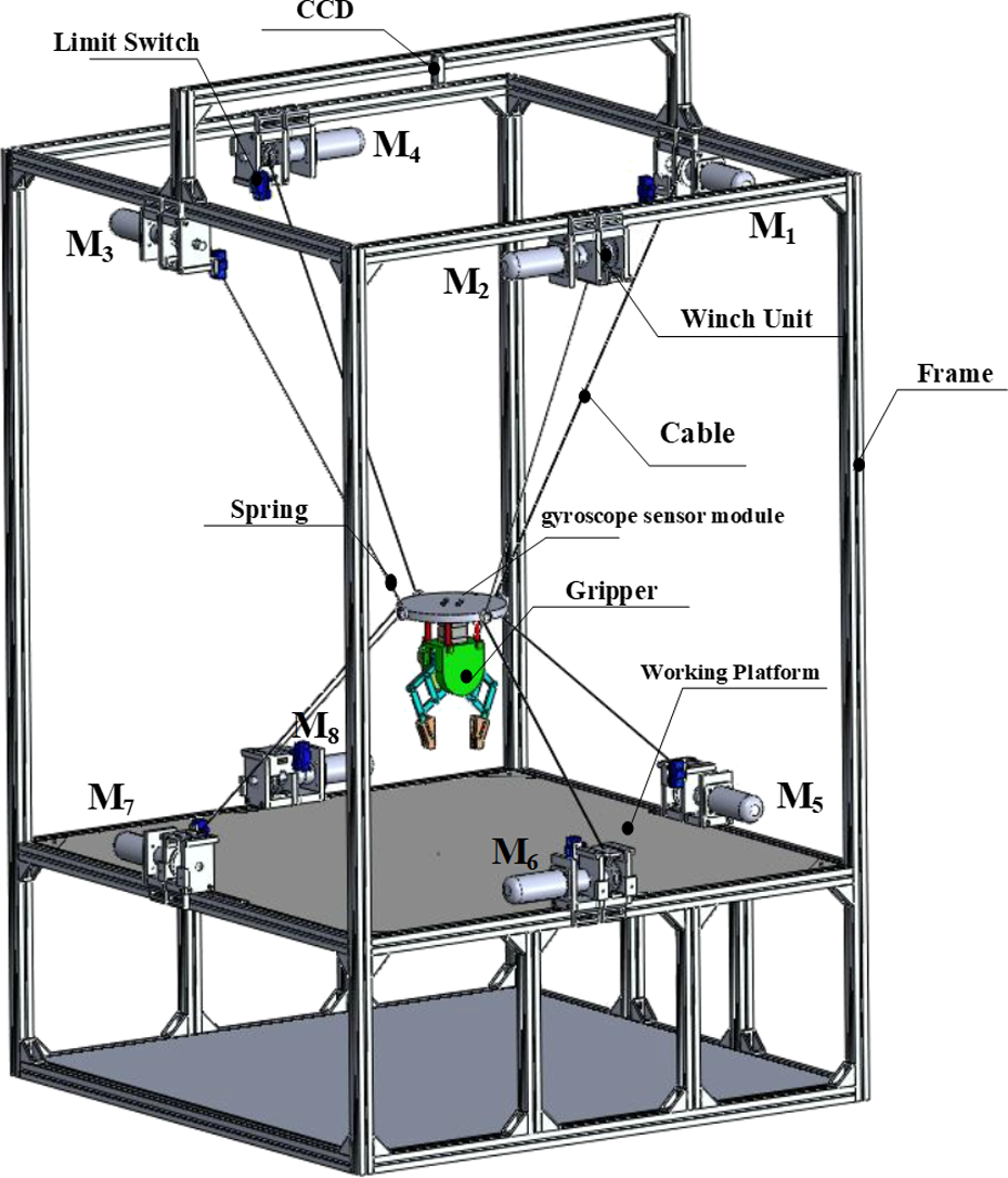
System configuration of a cable-driven parallel robot.
The suspended end-effector is controlled by alternate current (AC) servomotors that can extend or retract the cables. Such servomotors are equipped with optical encoders that can be used to measure the lengths of the cables. The cables are normally wound on the winch unit, and incremental encoders provide information about the current angle of servomotors from which the cable lengths can be computed. The two motion control board ADLINK PCI-8164 (ADLINK Technology Inc., Taiwan) offers eight independent channels, each of which consists of a TTL/RS422 compatible encoder interface and one analog ±24 V analog output, which is the input command to drive a servomotor. The servomotor is also equipped with an integrated incremental encoder with a resolution of 10,000 pulses per revolution. The stepping motor is used to drive the suspended gripper of the end-effector in such a robot system. The Arduino Mega 328 is used as the control board for driving the stepping motor. 6
The robot is equipped with a set of sensors that yield pose information. The inertia measurement unit (IMU; Model: GY-521 by InvenSense Inc., San Jose, CA, USA) is mounted on the cable-suspended robot to detect inclination information. The IMU sensor module consists of an accelerator, a compass, and a gyroscope. A program has been implemented in Arduino environment to allow the sensor to sense the angular displacement around the reference axes. The wireless camera (CCD) and the standard image processing algorithm are used to monitor real-time scenarios and to estimate the real position of the suspended end-effector. A limit switch (LS) ensures that the cables remain on the reel track. Both IMU and CCD sensors have been implemented in Arduino card to allow the sensor to sense the angular displacement around the reference axes. An LS ensures that the cables remain on the reel track. The control programming and machine algorithms were established using the National Instrument (NI) commercial package LabVIEW (Figure 2). Figure 3 displays the motion of the proposed cable-driven parallel robot. Accordingly, the suspended gripper is forced along the desired trajectory by changing the cable lengths.

Control implementation for the proposed system.

Motion concept for cable-driven robot.
One end of each cable is connected to the suspended end-effector, while the other end rolls through a winch unit that is fixed to its cable tower. This last cable end is fed into a servomotor that controls the length of all of the cables. Figure 3 displays the motion of the proposed cable-driven parallel robot. Accordingly, the suspended gripper is forced toward the desired trajectory by changing the cable lengths.
Kinematics
The derivation procedure for kinematic analysis can be applied to the geometric concept of the proposed cable-suspended robot, as depicted in Figure 4. Figure 5 displays the top view of the specific system and assigns the quadrant symbol to the workspace. In such a system, the cable lengths are changed as determined by the orientation of the suspended platform and calculated using the motor-side incremental encoder. In many applications, the extension of the cable is measured using an encoder that is attached to a reel. However, measuring the inclination of the cable is much more difficult 21 Therefore, this section will present a simple algorithm for estimating the orientation thereof for such specific suspended manipulator structure. However, the computation procedure can be applied to the similar MDOF cable-driven parallel robot system.

Control implementation for the proposed system.

Quadrant description fot the proposed system.
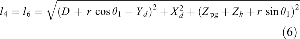
An inverse kinematic analysis of the proposed cable-driven robot system is carried out using the coordinate system that is presented in Figures 4 and 5. The distances from the fixed point on the main frame to the point on the end-effector are given by li (i = 1,…, 8). The lengths of the upper cables are denoted as li (i = 1, 2, 3, 4) and lengths of the lower cables are specified as li (i = 5, 6, 7, 8), respectively. To simplify the measurement of the position and orientation of the proposed system, the formula for kinematic computation can be used in relation to the X and Z axes in Figure 4. Similarly, the kinematic analysis process can be applied to other corresponding cables. Assume that θ1 is the tilt angle of the end-effector and θ2 is the angle of inclination of the cable from the X-axis. Here, the length l 1 is used in an example of computing the kinematic orientation, as is the corresponding length. Hence, the corresponding arrangement of the length l 1 is given by


where r is the radius of the suspended platform; l 1 is the corresponding cable length; D is the distance between the center of the suspended platform and the main rigid frame; and Z is the distance between the center of the suspended platform and the top of the cable frame tower. 5
Hence, the corresponding cable length l 1 can be directly calculated from equations (1) and (2) as

The other corresponding cable lengths li can be similarly calculated.
The height of the suspended platform Z is defined as the difference between the Zmax and Zh .

where Zmax is the maximum height from the suspended platform to the top of the main frame, and Zh is the displacement of the suspended platform from its original point.
The slip displacement of the upper cables length


where
If the suspended platform position displacement from the origin is


After li
is obtained from equation (6), the li
that is obtained from equation (6) is substituted into equation (5), and the slip displacement of the corresponding upper cables
The upper motor angle


As the servomotor is equipped with an optical encoder with a resolution of 10,000 pulses/rev, the motor angle,


Accordingly, equation (5) can be substituted into equations (7) and (8) to yield the corresponding cable length in terms of the pulse units.
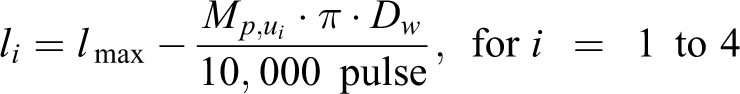

The critical issue in this system is controlling not the position of the motor but the cable length. Since the diameter of the winch Dw is constant but the cable length is directly proportional to the encoder output value, the latter can be directly controlled. Therefore, the lengths of the cables are measured using encoders that trace their release, so no extra equipment is required. 5
Controller implementation
Most multi-cable-driven robots suffer from interference among the cables under tension; even a simple point-to-point motion requires a complex control methodology to reach a target. Therefore, the effective solution to a specific optimization problem always requires laborious exploration to find the best control values; this process always has a high computational cost. To resolve the above issue, this work develops a hierarchical control method to satisfy the positioning control requirement; the method involves a main control mode and a fuzzy modification control mode. The quadrant selection strategy is utilized herein to develop a new and efficient control algorithm for MDOF cable-driven robots that are driven by eight cables. Owing to the above issue with cable-driven parallel robots, the whole control structure decomposes into upper level and lower level missions. A main control mode, which is an upper level control mode, is used to force the suspended end-effector close to the desired point by exploiting the open-loop control concept. Then, the fuzzy modification control mode, which is the lower level control mode, is used to actuate the end-effector for accurate positioning through a feedback control scheme. This lower level control is modified using fuzzy logic to generate a fine control action. The task here is to design a fuzzy controller that refines the control action and yields a tracking error e of less than a pre-specified small value, ε.
Figure 6 shows a flowchart of the entire control scheme in the experiment. After the desired control target is provided, the control must be modified as presented in the figure.
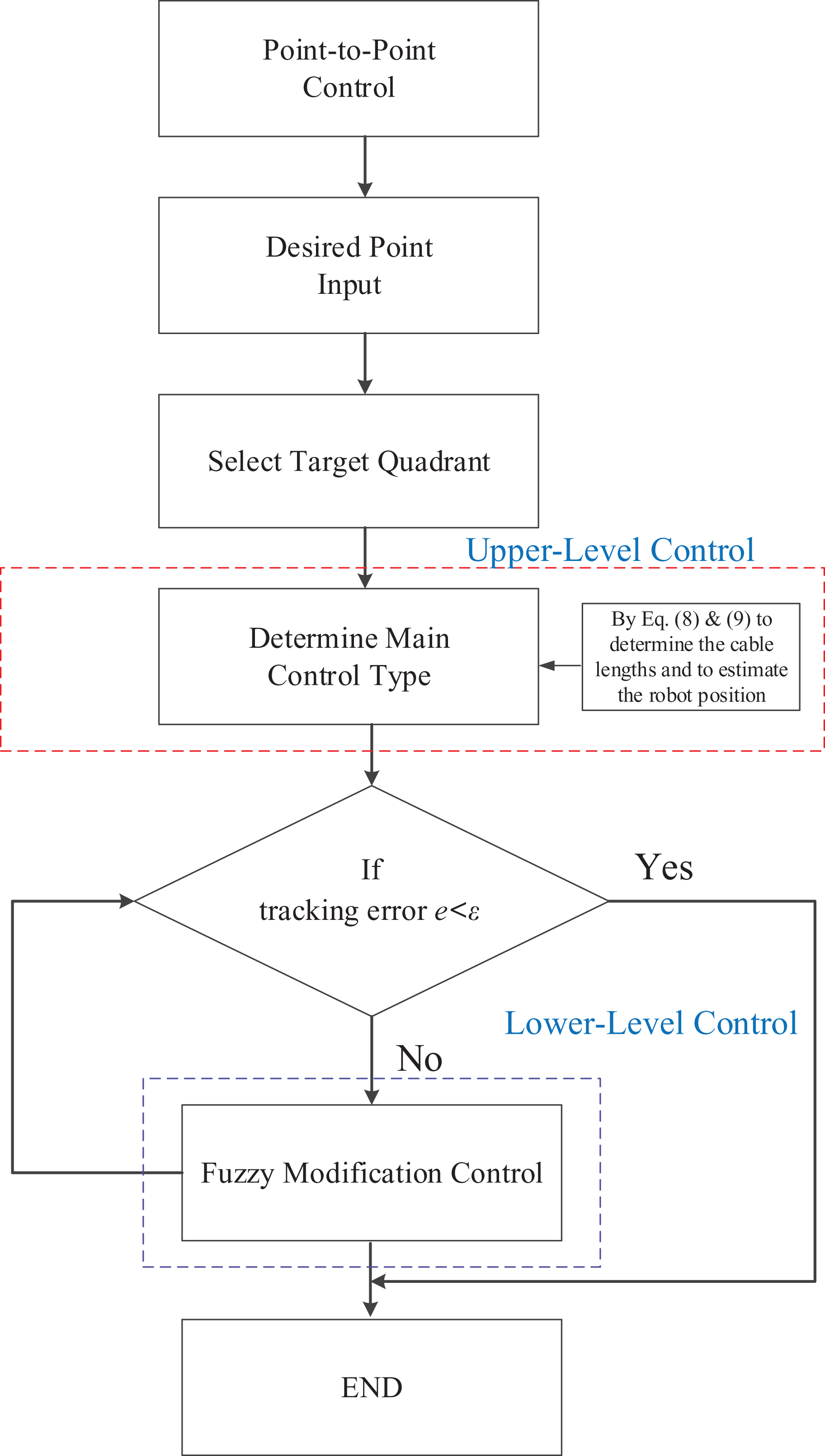
Control flowchart for the proposed cable-suspended robots system.
Main control mode (upper level control)
Knowledge of the control target of the proposed cable-driven parallel robot is critical in practice. The upper level control mode is used to track the suspended end-effector to the desired target region. For the purposes of this work, a main controller is used to achieve this goal. To implement the proposed control technique, the control target space is characterized as having four quadrants (I, II, III, and IV), three axes (
As stated above, the cable-driven parallel robot is a coupled system. If the length of any cable is altered, then the angles and the tensile forces of the cables will also vary. The lengths of the cables can be altered using the servomotors. The cable lengths are computed from the positions of the suspended end-effector using a kinematic model that is described in the “Kinematics” section. The forward kinematics are the opposite of inverse kinematics and are used to obtain the positions from known cable lengths. Accordingly, the upper level control mode exploits the concept of open-loop control and moves the end-effector to the desired point by changing the cable lengths.
The manipulating servomotors are assigned numbers M1–M8, and motor M i is used to regulate the corresponding cable lengths li using equation (9). Figure 7 presents the rule that governs the regulation of the main control module. The main function of such a control mode is to avoid unnecessary intense tensioning on the cable pairs.

Structure of the upper level control for the proposed cable-driven robots system.
First, the suspended end-effector is moved to a specified point in quadrant I; one group of motors (M1, M4, M5, and M8) retracts its appropriate cables, while the other group of motors (M2, M3, M6, and M7) simultaneously extends its corresponding cables. Similarly, if the target points are located in quadrant II, then the group of motors (M3, M4, M7, and M8) retracts the corresponding cables, and the other group of motors (M1, M2, M5, and M6) simultaneously extends the corresponding cables. Hence, the other regulations that govern the target point in the quadrant region may be obtained from Figure 7 to determine which motors retract or extend their corresponding cables.
To manipulate the suspended end-effector to a particular point on the
To regulate as diagonal line, only the lengths of the two coupled cables have to be changed. The diagonal lines of the payload can be controlled using knowledge of the geometry of the suspended end-effector. Accordingly, the lengths that correspond to (M1 and M7) and (M3 and M5) can be changed to regulate θx, and the lengths that correspond to (M4 and M6) and (M2 and M8) are changed to regulate θy. Therefore, one pair of motors M1 and M7 (or M4 and M6) and another pair of motors M3 and M5 (or M2 and M8) can be adjusted simultaneously while the four cables that are associated with the other motors are kept unadjusted to prevent rotation of the suspended end-effector. Specifically, l 1 and l 7 (or l4 and l 6) can be lengthened as l 3 and l 5 (or l 2 and l 8) are shortened.
Fuzzy modification control mode (lower level control)
The suspended end-effector is close to the target point in the main control mode. The lower level control performs fine positioning adjustments. Therefore, it is responsible for computing in real time the set of cable tensions that corresponds to a given force on the end-effector. Hereafter, the fuzzy modification rules are applied to regulate the adjustment factors to improve functioning even with unpredicted variations in system performance.
The fuzzy modification control module has tracking error e and its rate of variation

where αi, βi, and γi are linguistic values of fuzzy variables that are used to express the discourse universe of fuzzy sets. Fuzzy quantities such as Negative Large (NL), Negative Small (NS), Zero (Z), Positive Small (PS), Positive Large (PL), and others are used in the statements, and the corresponding membership functions are thus required.
The fuzzy modification rule is based on a characterization of the control space as having four quadrants, three axes, and two angles of rotation (Figure 7). Owing to symmetry, quadrants I and III share the same fuzzy rule base and quadrants II and IV use the same fuzzy rule base. Each rule base is constructed with three axes and two angles of rotation. Membership function parameters are tuned off-line according to heuristic rules. A fuzzy Mamdani-type model was constructed to approximate such an eight-cable-driven robot system within a small range of states close to its equilibrium state. Based on the Mamdani model, a fuzzy controller was designed to perform fine positioning adjustments. Here, the fuzzy linguistic terms PS and PL denote the retracted cable lengths and NS and NB denote the extended cable lengths. The fuzzy linguistic terms Z mean null action.
To move the suspended end-effector to the assigned point in quadrant I or III, one group of motors (M1, M4, M5, and M8) use the same membership function, while the other motors (M2, M3, M6, and M7) use a different membership function to determine the fine motion control force f. Similarly, if the target points are located in quadrant II or IV, then the group of motors (M3, M4, M7, and M8) use the same membership function, and the other group of motors (M1, M2, M5, and M6) adopt another membership function.
If the target points are located on the X-axis, then the group of motors (M1 and M5) adopt the same membership function rule bases, and the other group motors (M3 and M7) and (M2, M4, M6, and M8) use another inference engine. Similarly, if the target points are located on the Y-axis, then the group of motors (M1, M3, M5, and M7) adopt the same membership function, and the other group of motors (M4 and M8) and (M2 and M6) use another membership function. When the target points are on the Z-axis, then motors (M1, M2, M3, and M4) adopt the same membership function, the other motors (M5, M6, M7, and M8) use another membership function. Accordingly, the lengths that correspond to (M1 and M7) and (M3 and M5) can be changed to regulate θx, and the lengths that correspond to (M4 and M6) and (M2 and M8) can be changed to regulate θy.
A total of seven fuzzy inference engines were implemented in this study. These output motor fuzzy control rules determine whether the motors retract or extend their corresponding cables. The suspended platform can be manipulated in the control space using the above technique to construct its individual fuzzy rule base.
Results and discussion
This section presents the experimental results that were obtained using the control algorithms of the proposed cable-driven robot. To confirm that the proposed robot that is driven using eight cables outperforms previously developed robots that are driven using four cables, 5 a preliminary oscillation performance test is conducted on both designs, as presented in Figure 8. First, point-to-point control of the suspended gripper is used to pick up a beaker in the manner Z(300 mm) →Z(80 mm)→Z(300 mm)→Z(80 mm). A gyroscope sensor module (model: GY-521 by InvenSense Inc., San Jose, CA, USA) is mounted on the suspended object to detect θx and θy, which specify inclination. Therefore, Figure 9 shows experimental results concerning Z-axis tracking that are obtained using the different cable-driven robots. The positioning error is also examined. The root mean square positioning error (RMSE) is defined as
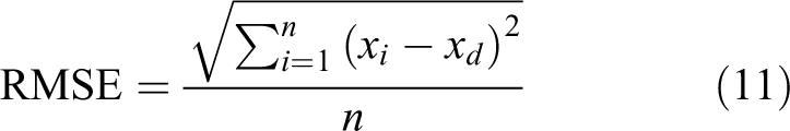
where n is the sample size, xd is the desired value, and xi is the measured value.

Physical diagrams for multi-cable-driven robot systems. (a) Four cables and (b) eight cables.

Physical diagrams for multi-cable-driven robot systems. (a) θx and (b) θy .
Figure 9 plots the inclination angles θx and θy that are obtained with various numbers of cables. The normalized root-mean-square (RMSE) deviation of θx is around 0.065° for the four-cable-driven robot and 0.045° for the proposed eight-cable system. The normalized RMSE θy deviation is approximately 0.044° with four cables and 0.041° with eight cables. The proposed eight-cable-driven robot system represented a marked improvement as the proposed eight-cable-driven parallel robot suffered from less cable oscillation than the four-cable-driven robot.
A repeatability test is conducted to confirm the accuracy of the developed cable-driven parallel robot to evaluate its performance. The measurement setup has nine test points, each with assigned coordinates (Figure 10). The proposed cable-driven parallel robot moves through the test points (points 1–9) five times and determines the coordinates of those points as it does so. The coordinates of the test points 1–9 are (−200, 200), (0, 200), (200, 200), (−200, 0), (0, 0), (200, 0), (−200, −200), (0, −200), and (200, −200), respectively. Moreover, the upper level control is as control mode A, and hybrid upper level and lower level control is control mode B.

Coordinates of the measured points for the repeatability test.
Clearly, the measured coordinates of the points are very close to each other. The standard deviation σ of the distance of a measured point from the actual point is around 3.96–0.84 mm. These results indicate that the robot system in control mode A reliably performs positioning.
However, the RMSE in positioning is not good and must be improved. The RMSEs of the measured coordinates of points 1–9 are (2.7, 3.3), (1.1, 8.1), (3.8, 6.2), (3.4, 5.4), (0.3, 0.3), (6.1, 0.5), (1.1, 8.6), (1.6, 12.9), and (1.3, 10) mm, respectively. Pure Control Mode A is weak in positioning control.
To improve the positioning error, Control Mode B is used in the experiments herein. As a result, the standard deviation σ of the distance from a measured point to the corresponding actual point is approximately 2–0.84 mm. These results also reveal that the robot system in Control Mode B is reliable for positioning. Moreover, the RMSEs of the measured coordinates of points 1–9 are (0.6, 0.56), (0.34, 1.29), (0.63, 1), (0.63, 0.28), (0.28, 0.4), (1, 0.52), (0.44, 1.56), (0.48, 1), and (0.6, 0.84) mm, respectively. Control Mode B offers significantly improved positioning performance. Hence, associated with Control Mode A, the RMSE positioning error is diminished to 76.6–86.5% while the hybrid Control Mode B is applied. This control scheme reduced the positioning error in a point-to-point control task.
To verify the favorable performance of the developed robot, a robot gripper was used to pick up a beaker that was filled with water and to pour the water into another container (Figure 11). Control Mode B reduced the spilling of the water by approximately 25%, indicating that it was effective in controlling the cable-driven robot system.

The gripper was assigned to pick up a beaker filled with water to pour water to another container.
Consequently, the forward kinematics are the opposite of inverse kinematics and are used to obtain the positions from known cable lengths. The open-loop control mode exploits the end-effector to the desired point by changing the cable lengths. Hereafter, the closed-loop control mode is applied to regulate the adjustment factors to improve positioning. The proposed control scheme does not involve the laborious computation that is required by Dykstra’s algorithm, 13 versatile tension distribution algorithm, 18,19 and has an approximately 20% lower CPU task execution time in the above applications. The algorithms that are developed in this study are easily implemented for real-time control and more suitable applied than previously proposed algorithms for use in university control course mechatronic kits. 12 –14,18,19
Conclusions
This study develops a MDOF cable-driven parallel robot with suspended end-effector. The proposed cable-driven parallel robots is composed of a rigid frame and an end-effector suspended from eight cables—four upper cables and four lower cables. The lengths of the cables can be changed by adjusting the lengths that are driven by servomotors. Additionally, the cable lengths are computed from the prearranged positions of the suspended end-effector by kinematic model indicated in the third section. However, most multi-cable-driven robots have difficulties with cable tension interfering with each other; hence, even a simple point-to-point motion still requires a complex control methodology to find a target goal. Accordingly, in order to resolve the above issue, this research proposes a hierarchical control methodology to satisfy the control requirement, which includes main control mode and fuzzy modification control mode. Owing to the difficulty of the cable-driven parallel robots, the whole control structure decomposes positioning control missions and allocates them into upper and lower level. The upper level control is responsible for tracking the suspended end-effector to the target region. The lower level control is concentrated on the fining modification for the positioning. The major benefit of such control methodology is to avoid unnecessary intense tensioning on the cable pairs. Experimental results reveal that the hybrid control mode significantly improves positioning performance. Such hybrid control scheme further improved reliable positioning and reduced the positioning error in point-to-point control task. The discussion of the broad issues deliberated in this investigation will be applied in aerostats, towing cranes, locomotion interface, and large-scale manufacturing applications that require cable-driven parallel robot.
Footnotes
Declaration of conflicting interests
The author(s) declared no potential conflicts of interest with respect to the research, authorship, and/or publication of this article.
Funding
The author(s) disclosed receipt of the following financial support for the research, authorship, and/or publication of this article: This work was financially supported by the Ministry of Science and Technology of the Republic of China, Taiwan for financially supporting this research under Contract No. MOST 103-2221-E-231-021- and National Instruments (NI) 2017 Academic Research Grant Program.