
Abstract
To meet the requirements in terms of large workspace, low inertia, and high degree of accuracy, a novel palletizing robot is introduced in this article. Utilizing spatial hybrid cable-actuated serial–parallel structure and parallelogram mechanism, the robot is able to achieve favorable potentials for stiffness, modularity, and reconfigurability. The kinematics and statics of the robot are investigated, and an algorithm is subsequently proposed to calculate the workspace of the limited degree of freedom cable-actuated serial–parallel manipulator. Then the workspace of the robot under different loads is calculated, and the topological properties of the workspace under different loads are compared and analyzed in detail. The results demonstrate that the proposed structure significantly enlarges the workspace and can also complete palletizing tasks effectively.
Introduction
Introduced in the 1980s, the palletizing robots are developed to implement the grabbing, handling, stacking, and unstacking tasks. With the increasing cost of labor and the reduction of robotic systems cost, the palletizing robots have been in ever increasing demands in the manufacturing systems, packaging and logistics industry, and so on.
Currently, several translational parallel robots, like diamond and delta, have been presented for picking and placing tasks. 1 Specially, the two degree of freedom (2-DOF) three-parallelogram planar parallel manipulator (PPM) that combines the advantages of parallel and serial robots has been widely used in palletizing. 2 The employment of parallelogram mechanisms makes the 2-DOF PPM has higher stiffness, lower inertia, and larger workspace than traditional serial and parallel palletizing mechanisms. 3 However, the high inertia of multirigid links and actuators on the rotating base greatly limits the further improvement of the palletizing performance.
For the remarkable characteristics, such as large workspace, high payload-to-weight ratios, soft actuating, 4 and easiness of reconfiguration, 5 a number of cable-driven parallel manipulators (CPMs) have been proposed for carrying objects, for instance, the NIST RoboCrane, 6 the FAST, 7 and the FALCON robot. 8 Since the cable can only provide positive tension, the cable must be at least one number more than the Cartesian motion DOF of the system to fully constrain the system. 5,9 Numerous research have been conducted on NIST RoboCrane-like CPMs, 10,11 such as the workspace determination 5,12 and the dynamic modeling and control. 13 –15 Alternatively, the fully constrained CPMs, like the FALCON robot, can provide better performances. 16,17 However, both the abovementioned fully and underconstrained CPMs occupy a large empty space, and the radiating cables in workspace definitely increase the risk of collision in comparison with other structures. 18
To overcome these drawbacks, the bioinspired limited DOF cable-driven system has attracted wide attentions from researchers. Generally, the limited DOF cable-driven system consists of limited DOF rigid structure and parallel actuating cables. The static conditions and performance of a cable-driven serial-link system for virtual reality were discussed in the study by Kino et al. 18 In the study by Behzadipour and Khajepour, 19 the tension ability of a cable-driven high-speed robot named BetaBot was studied. Similarly, a differentially cable-driven parallel robot was proposed by Khakpour et al. 20 However, the length of the passive link limits the workspace of these two robots. Based on the study by Zhang and Gosselin, 21 the kinetostatic model of hybrid cable-actuated parallel manipulators with a constraining leg was proposed by Hassan and Khajepour. 22 The static and stiffness model of serial–parallel manipulators is established by Hu et al. 23 Similarly, the workspace optimization and control of a cable-driven arm exoskeleton were presented by Mao and Agrawal, 24 and a standard cable-driven module for building reconfigurable systems was studied by Lim et al. 25
Inspired by these aforementioned serial–parallel manipulators and CPMs, we present a novel 6-DOF cable-actuated serial–parallel palletizing robot (CASPR). In this article, a modified algorithm is proposed for the calculation of the workspace of the serial–parallel limited DOF cable-driven manipulator. By employing parallel cables, the parallelogram mechanism, and the hybrid serial–parallel structure, the inertia of the whole robot is significantly reduced and the workspace of the CASPR is increased.
This article is organized as follows. In “conceptual design” section, we present the design details of the CASPR. Then, inverse kinematics and statics of the CASPR are presented in “inverse kinematic and static analysis” section. The algorithm to determinate the workspace is proposed in “workspace determination” section. In “simulation results and analysis” section, a simple trajectory is given to verify the kinematic model, and the workspace of the CASPR with different loads is calculated and analyzed in detail by aforementioned algorithm. The last section concludes this article.
Conceptual design
As shown in Figure 1, the CASPR is a spatial hybrid serial–parallel mechanism. For conveniently describing the whole structure, the CASPR is divided into lower and upper structures by the moving platform.

The simplified 3-D model of the CASPR. (a) The windlass module that used to actuate cables, (b) the gear reducer system on the base, (c) the torsional springs on axis 5, and (d) details of the gear box. CASPR: cable-actuated serial–parallel palletizing robot.
The lower structure mainly consists of a passive constrained mechanism and four parallel actuating cables. The passive constrained mechanism is composed of the back arm, four tensioning cables, two swivel plates, and universal joints. Moreover, the back arm and tensioning cables have the same length and are parallel to each other. According to the reciprocal screw theory, the passive constrained mechanism is equivalent to a 4SS/RUUR parallel mechanism, 26 and the upper swivel plate has two translation freedoms that are perpendicular to the back arm. The moving platform is mounted on the upper swivel plate and can be actuated by four cables to rotate around axis 3. Thus, the lower structure has three freedoms. The gear reducer system in the base can actuate the lower universal joint and the lower swivel plate to make them rotate around the same axis (see Figure 1(b)). Then, the tensioning cable and the back arm can transfer torque from the base to the upper swivel plate while supporting the whole structure. Moreover, the distribution of the windlass module (see Figure 1(a)) can be easily adjusted and the slope of the base can tilt of α degree toward pallets to maximize the intersection of the workspace and pallets (see Figures 1 and 2).

Schematic diagram of the lower structure.
The upper structure mainly consists of the gearbox and the forearm. The gearbox is fixed on the moving platform and can transfer the input rotations of the upper universal joint and the upper swivel plate into rotations of the rotating drum and the active shaft, which actuates the forearm to rotate around axes 4 and 5. The angle between axes 3 and 4 is set to be α and the forearm can constrain axis 6 parallel to axis 4 by utilizing the parallelogram mechanism. Without considering the DOF of the wrist, the upper structure is actually an underconstrained 2-DOF hybrid cable-actuated parallel mechanism. Note that a pair of torsional springs is added on axis 5 (see Figure 1(c)) to bear the upward force at the moment of grasping.
The novel features of the CASPR can be listed as follows: (1) the inertia of the structure is further reduced by transferring the actuators to the ground and utilizing cables; (2) the modular windlass can be easily rearranged to accommodate different tasks; (3) the serial–parallel structure enlarges the workspace of the CASPR in comparison with the CPMs in the studies by Behzadipour and Khajepour 19 and Khakpour et al. 20 ; and (4) compared with the cable-driven arm in the study by Lim et al., 25 the employment of the parallelogram mechanism makes the CASPR more suitable for palletizing.
Inverse kinematic and static analysis
In this section, the inverse kinematic and static models of the CASPR are introduced. Since the joint variables of the constraining serial linkage in structure can describe the configuration of the robot independently, the joint variables of six axes θi shown in Figure 1 are selected to describe the configuration of the robot. For the convenience of discussion, two passive rotational DOFs of the lower universal joint and the swivel plate are fixed. The rotation limits of θi are specified in Table 1.
The range of the motion for six axes.

The initial configuration coordinate frame system is shown in Figures 2 and 3. The global coordinate frame
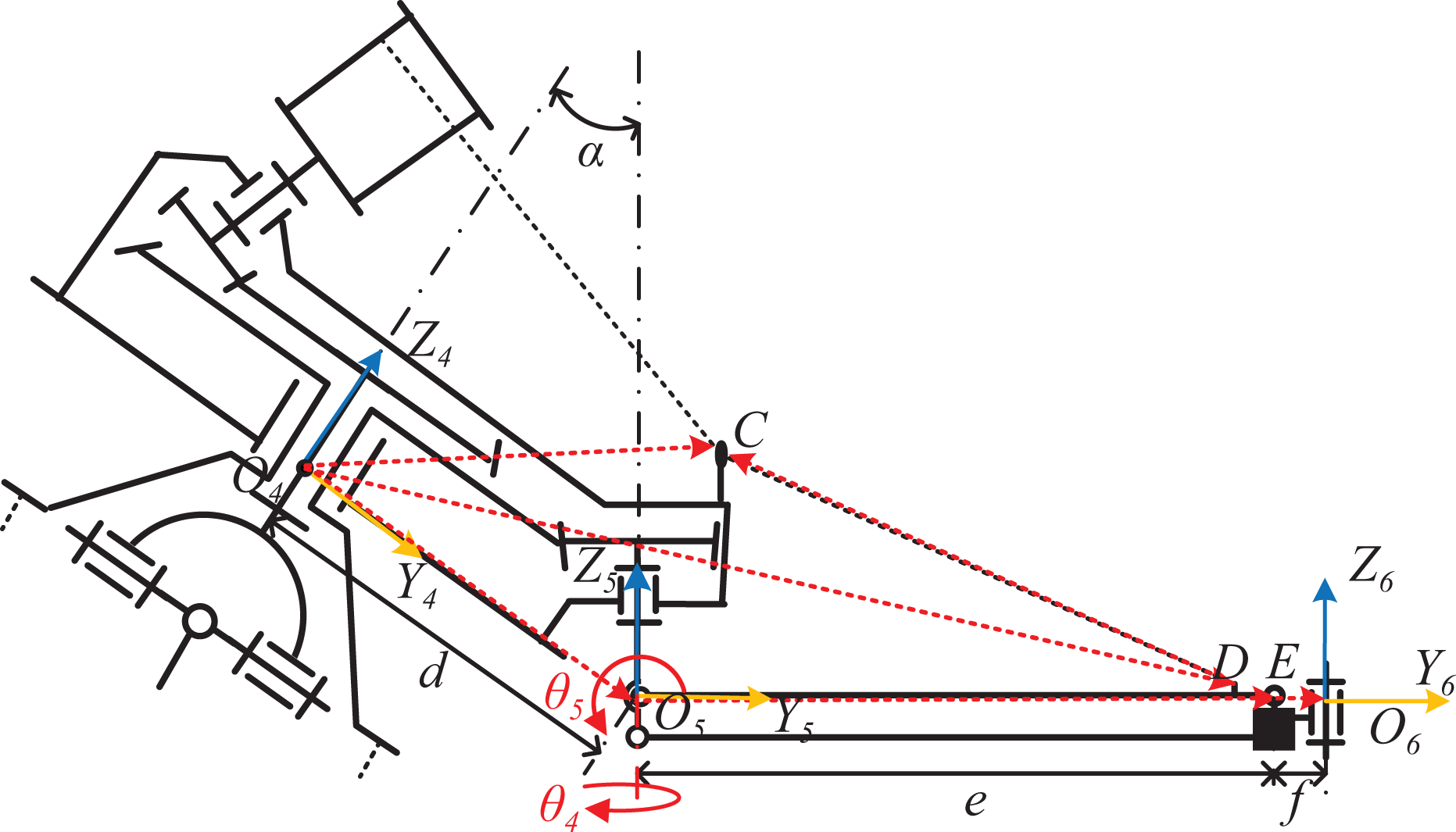
Schematic diagram of the upper structure.
Inverse kinematics
Schematic diagrams of the lower structure and the upper structure are shown in Figures 2 and 3, respectively. The forward kinematic transformation from the base to the moving platform can be written as

where
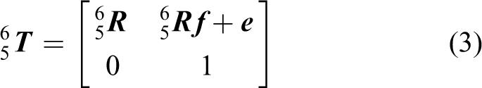
Similarly, the forward kinematic transformation from the moving platform to the end effector can be written as

Based on the arrangement of the local frames and parameters, we can derive
Due to the constraints of the parallelogram mechanism in the forearm,
where
Assuming that the cable attachment points

where

Taking the dot product of both sides of equation (5) yields

where li denotes the length of the ith cable.
As shown in Figure 3, the vector loop equation associated with the cable actuating forearm can be written as

where the vector

Static analysis
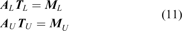
Static equilibrium equations of the whole structure can be written in the form of

where the structure matrix
Equation (9) can be written in the block form as

where
Due to the floating axis in the proposed structure, the structure matrixes cannot be derived with respect to a unitized frame like the traditional CPMs.
25
To derive the structure matrix of the lower structure
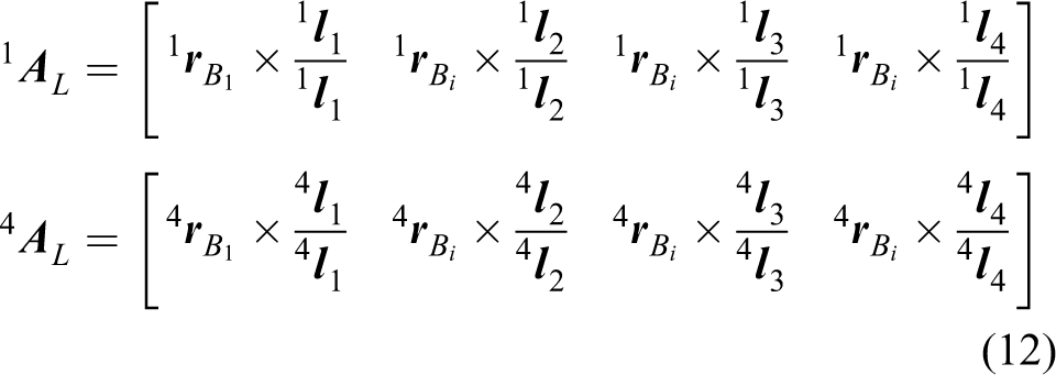
where
where
Since the rotation θ
1 of the back arm about axis X
1 disables axis 2 coinciding with the frame axis Y
1,

Recombining the first two rows of

Similarly, the upper structure matrixes with respect to frame Oj can be derived as

where
Adjusting

Then, the structure matrix of the upper structure can be obtained by removing the third row of

Workspace determination
The modified method to determine the workspace of the CASPR is constructed in this section. The static workspace of the CASPR is defined as all positions that satisfy the static equilibrium condition, and all tensions (toques) in cables (joints) are within the acceptable limits as well. In general, the condition can be expressed as

with

where
Similar to the available wrench set that was proposed by Bouchard et al., 12 the available torque set (ATS) is defined as the set of toques that the robot can generate on its joints. From equations (19) and (20), the ATS can be described as

where

The affine map transforms the unit hypercube {α} to the ATS. The ATS is the convex hull of all possible torques that can be generated by the extreme actuating forces of actuators. Based on equation (21), the extreme torques can be derived as

where ⊕ donates the Minkowski sum,
The static equilibrium condition can be verified by checking whether −
The quick hull algorithm is adopted in this study to find out the convex hull. The algorithm has been widely used in high-dimensional cases and it has an
Without losing the generality, actuator numbers of parallel mechanisms are assumed to be
As for the CASPR in a case of
Moreover, the unbalance of any parallel mechanism in serial–parallel manipulators will lead to the collapse of the whole structure. Then, the calculation amount can be further decreased by verifying the static equilibrium condition from the low-dimensional parallel mechanism to the high-dimensional parallel mechanism.
The algorithm is illustrated by the proposed robot. The flowchart of the algorithm is shown in Figure 4. It is mainly composed of three steps provided as follows:
For the configuration θj
, the static equilibrium condition of the upper structure should be verified firstly by checking whether −
Similarly, once the static equilibrium condition of the lower structure is verified to satisfy the demands, the set j = j + 1 goes to the next configuration; otherwise, it proceeds to the next step.
Computing the positions of O
5 and O
6 in the global coordinate to check whether the configuration meets the condition of

Flowchart of the proposed algorithm.
Simulation results and analysis
In this section, the inverse kinematic model is verified by a specified trajectory, and the static workspace of the CASPR under different loads is studied by the proposed algorithm. Table 2 shows the specifications of the robot.
Specifications of the robot used in the simulation and the 3-D modeling.

The specified trajectory expressed in the joint space is

As shown in Figure 5(a), the extensions of five actuating cables are tested for the given trajectory. Simulation results show that the actuating cables move smoothly. Moreover, the simulation data sets are used to drive the 3-D model in SolidWorks, as shown in Figure 5(b). The rotation of axis 3 in the simulation is set at zero, which keeps the end effector horizontal during the movement.

Simulation of the movements of the 3-D model while tracking the given trajectory.
The workspaces are performed when the end-effector loads are 0, 30, and 60 kg . The limits of the cable tension and the active joint torque are set as
Based on the proposed algorithm, the static equilibrium condition of the upper structure is firstly verified due to its low dimension. According to equation (11), the static equilibrium equation of the upper structure contains three variables θ 3, θ 4, and θ 5. Without losing the generality, four values of θ 3, such as 0°, 15°, 30°, and 45°, are, respectively, selected in the calculation, and θ 1 and θ 2 are set at zero.
The upper structure workspace can cover the whole joint range when the end-effector load is small. However, the shape of the workspace becomes more complex as the load increases. For instance, when the load is 60 kg, the workspaces for different values of θ 3 are shown in Figure 6. In the figure, the surface corresponds to the position of the end effector. Notably, with the increase in θ 3, a gap and a hole successively present at the bottom and the center of the workspace. As the gap and the hole expand, the workspace firstly changes from a simple connected space (see Figure 6(a) and (b)) to a path-connected space (see Figure 6 (c)) and eventually to a path disconnected space (see Figure 6(d)). Moreover, the area of the upper structure decreases rapidly as shown in Table 3. In other words, the topological properties and the area of the upper structure workspace become worse with the rotation of the moving platform.

Computed workspaces for different values of θ 3 (a) θ 3 = 0°, (b) θ 3 = 15°, (c) θ 3 = 30°, and (d) θ 3 = 45°.
Areas of the upper structure workspace for different values of θ 3.

To ascertain the cause of the gap and the hole, the ATSs of two configurations

The ATSs and the joint torque points for the configurations of
When the load is 30 kg, the upper structure workspaces for different values of θ 3 are shown in Figure 8. Due to the decrease in the end-effector load, the upper structure can balance the load in any posture when θ 3 varies within the range of 0°–45°. As shown in Figure 8(a) and (b), the workspace is able to cover the whole joint range without any gap or hole. Note that, when θ 3 varies within the range of −45° to 0° under the same condition, the workspace will be a mirror symmetry of the computed results.

Workspaces of the upper structure for a load of 30 kg and different values of θ 3. (a) The workspace of the upper structure expressed in joint spaces and (b) the computed position of the end effector corresponding to the workspace shown in (a).
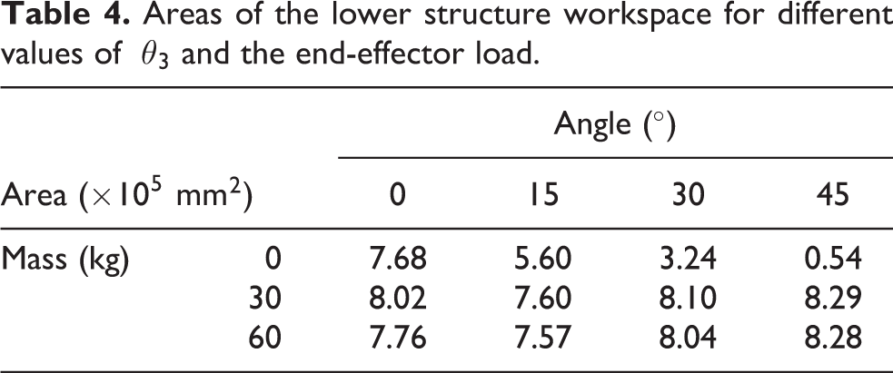
The lower structure workspaces with different loads are expressed in joint spaces (see Figure 9). Here, both θ 4 and θ 5 are set at zero for convenience. Notably, when there is no load on the end effector, the workspace shrinks rapidly with the increase in θ 3 (see Figures 9(1.a) to (1.d) and 10(b)). However, the lower structure workspace becomes insensitive to θ 3 as the load increases (see Figure 9(2.a) to (2.d) and (3.a) to (3.d)). According to the results plotted in Figure 9, the corresponding position of the center point of the moving platform O 4 is shown in Figure 10. It can be seen that the workspace of the lower structure changes dramatically when there is no load on the end effector, and the shrinkage and expansion of the workspace only occur at the edge of the workspace when the load is applied on the end effector (see Figure 10(b)). In Table 4, when the load of the end effector is 30 kg or 60 kg, the area of the workspace remains at a high level. In other words, the increase in the load makes the lower structure workspace insensitive to the rotation of the moving platform.

Workspaces of the lower structure expressed in joint spaces for different values of end-effector loads and θ 3. (1.a) to (1.d) workspaces with no load on the end effector. (2.a) to (2.d) workspaces with a 30-kg load on the end effector. (3.a) to (3.d) workspaces with a 60-kg load on the end effector.

Computed positions of the origin O 4. (a) Corresponds to Figure 9(1.a) to (1.d) and (b) corresponds to Figure 9(2.a) to (2.d).
Areas of the lower structure workspace for different values of θ 3 and the end-effector load.
As shown in Figure 11, the aqua polyhedron represents the ATS of the configurations when

Computed ATS of the position
Finally, the complete workspace of the CASPR derived when the end-effector load is 30 kg. According to the aforementioned analysis, θ 3 is set to be zero to simulate routine operations. As plotted in Figure 12, the complete workspace can very well cover the front and the side area of robot. In addition, the overall volume of the computed workspace is calculated to be 5.18 × 108 mm3, which is sufficient for most palletizing works. Note that, for some requirements of special operations, the complete workspace can be extended by the rotation of the moving platform.

The complete workspace of CASPR when the end-effector load is 30 kg and θ 3 is zero. (a) The whole workspace and (b) the cross-sectional view of the whole workspace at x 6 = 0. CASPR: cable-actuated serial–parallel palletizing robot.
Conclusions
In this article, a novel CASPR has been proposed and the inverse kinematic and static models of CASPR have been formulated. An algorithm for serial–parallel limited DOF cable-driven robots was proposed for the calculation of the workspace of the CASPR. The workspace of the CASPR under different loads was obtained and the topological properties of the workspace were compared and analyzed in detail using the proposed algorithm. The results indicated that the topological properties and the area of the upper structure workspace were sensitive to the values of the end-effector load and the joint angle of axis 3. On the contrary, the lower structure workspace was more robust when there was a load on end effector. Also, the reasons for the variations in the topological properties and the area for the workspace were revealed. The computed results of the general work model verified that the proposed serial–parallel CASPR had a bigger workspace than the single-level CPMs, and it was more qualified for palletizing works than traditional cable-driven arm exoskeletons.
Footnotes
Declaration of conflicting interests
The author(s) declared no potential conflicts of interest with respect to the research, authorship, and/or publication of this article.
Funding
The author(s) disclosed receipt of the following financial support for the research, authorship, and/or publication of this article: This work was supported by the National Natural Science Foundation of China (51575150 and 51505114).