
Abstract
This paper investigates the stiffness modelling of a 3-DOF parallel manipulator with two additional legs. The stiffness model in six directions of the 3-DOF parallel manipulator with two additional legs is derived by performing condensation of DOFs for the joint connection and treatment of the fixed-end connections. Moreover, this modelling method is used to derive the stiffness model of the manipulator with zero/one additional legs. Two performance indices are given to compare the stiffness of the parallel manipulators with two additional legs with those of the manipulators with zero/one additional legs. The method not only can be used to derive the stiffness model of a redundant parallel manipulator, but also to model the stiffness of non-redundant parallel manipulators.
Introduction
Parallel manipulators have attracted much attention from the academic and industrial communities due to potential applications not only as robot manipulators but also as machine tools. Compared to serial manipulators, parallel manipulators bring the benefits of much higher payload-mass ratios, higher stiffness and better dynamic performance [1–3]. However, relatively small workspace and the abundance of singularities within the workspace partly nullify the aforementioned advantages. It has been shown by some researchers that redundant actuation is an effective method to tackle these shortcomings [4–5]. Redundant actuation eliminates singularities, increases the usable workspace and partially controls the internal forces [6–8]. Thus, redundantly actuated parallel manipulators are rapidly becoming a focus of research due to the multitude of potential advantages they provide [9–11].
Stiffness performances are of great importance for parallel manipulators, particularly those which are used as machine tools, since higher stiffness allows higher machining speeds and feeds while providing the desired precision, surface finish and tool life. The stiffness of a parallel kinematic machine (PKM) in some configurations in the usable workspace might be lower than desirable. Therefore, it is important to carry out the stiffness modelling and to evaluate the stiffness of a PKM in the usable workspace. Due to the complex geometry together with the changing rigidity throughout the workspace, it is a complex task to achieve the stiffness of a parallel manipulator. It can be accomplished with the aid of finite element analysis (FEA) software such as ANSYS, ABAQUS and NASTRAN [12]. For a parallel manipulator with fixed length and linear drives, the FEA model has to be remeshed over and over again to make the nodes on the machine frame match with those on the sliders, which vary with the changing configurations of the manipulator. This results in a very tedious and time-consuming routine [13].
An accurate stiffness matrix of a parallel manipulator in stiffness modelling is critical for stiffness evaluation. Some publications have concentrated on the stiffness modelling of parallel manipulators [14–16]. Gosselin [17] and Svinin [18] investigated the stiffness of the Stewart platform and the mapping between the driving force and the platform deformation based on the Jacobian matrix. Li et al. [19] derived intuitively the stiffness matrix of a 3-PUU PKM based on an alternative approach considering actuations and constraints. However, there is little work on the stiffness modelling of redundant parallel manipulators and even less work on the stiffness comparison of redundant parallel manipulators with their non-redundant counterparts.
In this paper, a stiffness modelling method is proposed to derive the stiffness of a parallel manipulator in six directions. Two performance indices are given to compare the stiffness of the manipulator without additional legs with the stiffnesses with one/two additional legs.
Structure description and kinematic analysis
Structure description
The parallel manipulator studied here, with two translational DOFs and one rotational DOF, is shown in Figure 1. It is composed of sliders A1A3 and A2A4, the moving platform B1B3, constant-length links A1B1 and A2B2 and extendable links A3B3, A4B4 and A5B5. One end of the links A1B1 and A2B2 is fixed to sliders A1A3 and A2A4, and the other two are fixed to the moving platform B1B3, respectively. When sliders A1A3 and A2A4 slide along the vertical guide rails, the moving platform can move in Y and Z directions. Extendable links A3B3 and A4B4 are driven by inner active actuators, with one end fixed to the sliders A1A3, A2A4 and the other two fixed to the moving platform B1B3 respectively. Extendable link A5B5 is also driven by an inner active actuator, with one end fixed on the beam and the other to the moving platform B1B3. It can be concluded that the manipulator has a 3-DOF motional capability even if links A4B4 and A5B5 are removed. In this paper, parallel manipulators with zero/one legs are as shown in Figure 1: without legs A4B4 and A5B5, or without leg A5B5, respectively.

Kinematic model of the parallel manipulator
As shown in Figure 1, two coordinate systems O –XYZ and O′–X′Y′Z′ are created. The global coordinate system, O–XYZ, is attached to the middle of the frame bottom, and the moving coordinate system, O′–X′Y′Z′, is positioned at point B1(B2) of the moving platform, where its Z′ -axis is along the direction of the constant-length link B1B3. The angle a is the orientation (pose) of the moving platform. [Ai]O and [Bi]O are defined as the position vectors of the points Ai and Bi with respect to O′ – X′Y′Z′, respectively. The position vector of the origin point O′ with respect to O–XYZ is r=[y,z]T. Let the position vector of the point Ai with respect to O–XYZ be [Ai]O. The position vector of the point Bi with respect to O – XYZ can be expressed as

where

where l1 and l2 are the lengths of two constant-length links A1B1 and A2B2, and l3, l4 and l5 are the lengths of the extendable links A3B3, A4B4 and A5B5.
The inverse kinematic solutions of the parallel manipulator can be written as

where e is the length of sliders A1A3 and A2A4 and the moving platform B1B3, h is the height of the column, d is the width between two columns, and z1 and z2 are the Z-directional position of points A3 and A4 on the sliders, respectively.
In stiffness modelling, the parallel manipulator is simplified as many spatial beam elements. Based on structural mechanics, the element stiffness matrix in the element coordinate system is built. Then, constraint processing according to the connection forms between two elements is performed for the element stiffness matrix. Finally, the global stiffness matrix is obtained by using the element integration method to integrate all the element stiffness matrices.
Element stiffness matrix
Let the end nodes of each element be m and n, the displacements of each node in the element coordinate system be

where
In the global coordinate system, the displacements of nodes m and n are
The displacements and force vectors of each node in the global coordinate system can be expressed as


where T is the coordinate transformation matrix from the element coordinate system to the global coordinate system, and
By substituting Eqs. (5) and (6) into Eq. (4), the relationship between node displacements and force vectors in the global coordinate system can be written as

where
Forms of connection between the elements can be divided into three types: rigid connection (e.g., the connection between the beam and the column), joint connection and insertion end. Elements with rigid connection can be integrated directly with the element matrices by the integration method. Elements with joint connection require treatment of DOF condensation. Elements with fixed ends require treatment for the insertion process. Before using the element integration method to obtain the stiffness model of the parallel manipulator, treatment of DOF condensation and insertion process should be performed for the element stiffness matrix, except for the rigid connection elements.
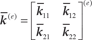
In the element coordinate system, the element stiffness matrix is divided into blocks to describe the process of DOF condensation. The stiffness equation of element (e) can be expressed as:

where

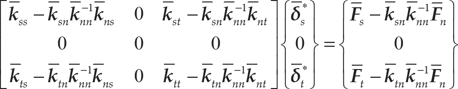
By substituting Eq. (9) into Eq. (8), the element stiffness matrix can be written as
The lower end of the column is fixed to the base and cannot move in any direction. Thus, fixed-end treatment should be carried out with the insertion process before integrating all the element stiffness matrices to obtain the global stiffness matrix.
Since node n is fixed,
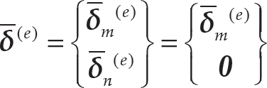
The element stiffness matrix in the element coordinate system can be expressed as
Since
All element stiffness matrices in the element coordinate system can be transferred to the global coordinate system. Then, the global stiffness matrix can be obtained by integrating all the element stiffness matrices in the global coordinate system. The following equation can be obtained:

where K is the global stiffness matrix of the parallel manipulator.
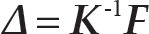
The stiffness model of the parallel manipulator in the global coordinate system can be written as

where F is the applied force vector of all nodes, and Δ is the displacement vector of all nodes.
The displacement vector of all nodes is derived as
Let the stiffness values of the i th stressed point in each direction be kxi, kyi, kxi, kmxi, kmyi and kmxi. Applying the force fxi in the X direction of the i th stressed point, the applied force vector of all nodes can be expressed as

Therefore, the stiffness of the i th stressed point in X direction can be expressed as

where δ6(i-1)+1 is the displacement of the i th stressed point in X direction.
Similar methods can be used to obtain kyi, kxi, kmxi, kmyi and kmxi.
Stiffness distribution
The proposed modelling method is used to derive the stiffness model of the 3-DOF parallel manipulator. The parallel manipulator is simplified as a structural system composed of a plurality of spatial beam elements, as shown in Figure 2. The 3-DOF parallel manipulator includes 14 nodes and 17 elements.

Nodes and elements of the 3-DOF parallel manipulator
The elastic modular is 210GPa and the Poisson's ratio is 0.3. The geometrical parameters of the 3-DOF parallel manipulator are l1 = l2 = 1150mm, d = 1170mm, h = 3160mm and e = 250mm. The cross-sections of the constant-length link, beam and columns are rectangles and the extendable links are annular, as shown in Figures 3 (a) and 3 (b), respectively. The cross-sectional parameters of constant-length link, beam, columns and moving platform are shown in Table 1. The cross-sectional parameters are Ro = 53mm, Ri = 40mm for the upper part of the extendable link, and Ro = 40mm and Ri = 0mm for the lower part [21].

Shapes of cross-section
Rectangular cross-sectional parameters (mm)

In order to verify the accuracy of the stiffness model, finite-element simulation software (Ansys APDL) is also used to find the stiffness of the parallel manipulator. The displacement of the moving platform can be obtained by APDL with the force imposing on the moving platform, and the stiffness of parallel manipulator can be easily obtained by the relationship between the displacement and the force of the moving platform. The stiffness of the 3-DOF parallel manipulator in the workspace with y ∊ [–400mm, 400mm], z ∊ [700mm, 1150mm], a = 0° is simulated by theoretical method and finite-element simulation, respectively.
Figure 4 shows the stiffness distribution with two additional legs obtained by using the method proposed in this paper and using the finite-element method. For both the method proposed in this paper and the finite-element method, the Y-directional and Z-directional position stiffness distributions are symmetrical with respect to the Z axis, due to the symmetrical architecture of the parallel manipulator with two additional legs. When the Z coordinate increases, the stiffness in each direction, except for the Z-directional position stiffness, goes down; Z-directional position stiffness increases due to the effect of an additional leg A5B5 near the centre of symmetry.

Comparison of theoretical calculations and simulation results
In order to validate the approach proposed in this paper with a finite-element approach, the mean stiffness values in each direction and the error rate between the values obtained by using the two approaches are computed and shown in Table 2. From Table 2, one may see that the theoretical values of the proposed method are consistent with the simulation values. The stiffnesses in each direction are also in close agreement. The overall trend is similar with very small fluctuation.
Theoretical values and simulation values

In order to evaluate the stiffness performance of the manipulator with two additional legs, the stiffness of the manipulators with zero/one additional legs is also investigated in the workspace, as shown in Figure 5. Compared with those of the manipulators with zero/one additional legs, the X-directional and Z-directional position stiffnesses and the Z-directional rotational stiffness of the manipulator with two additional legs are much higher. The distribution of the X-directional rotational stiffness of the manipulator without additional legs is asymmetrical in the workspace. However, the distribution of the X-directional rotational stiffness of the manipulator with one/two additional legs is symmetrical due to the symmetrical architecture. The manipulator without additional legs has the lowest stiffness among the three parallel manipulators in each direction.
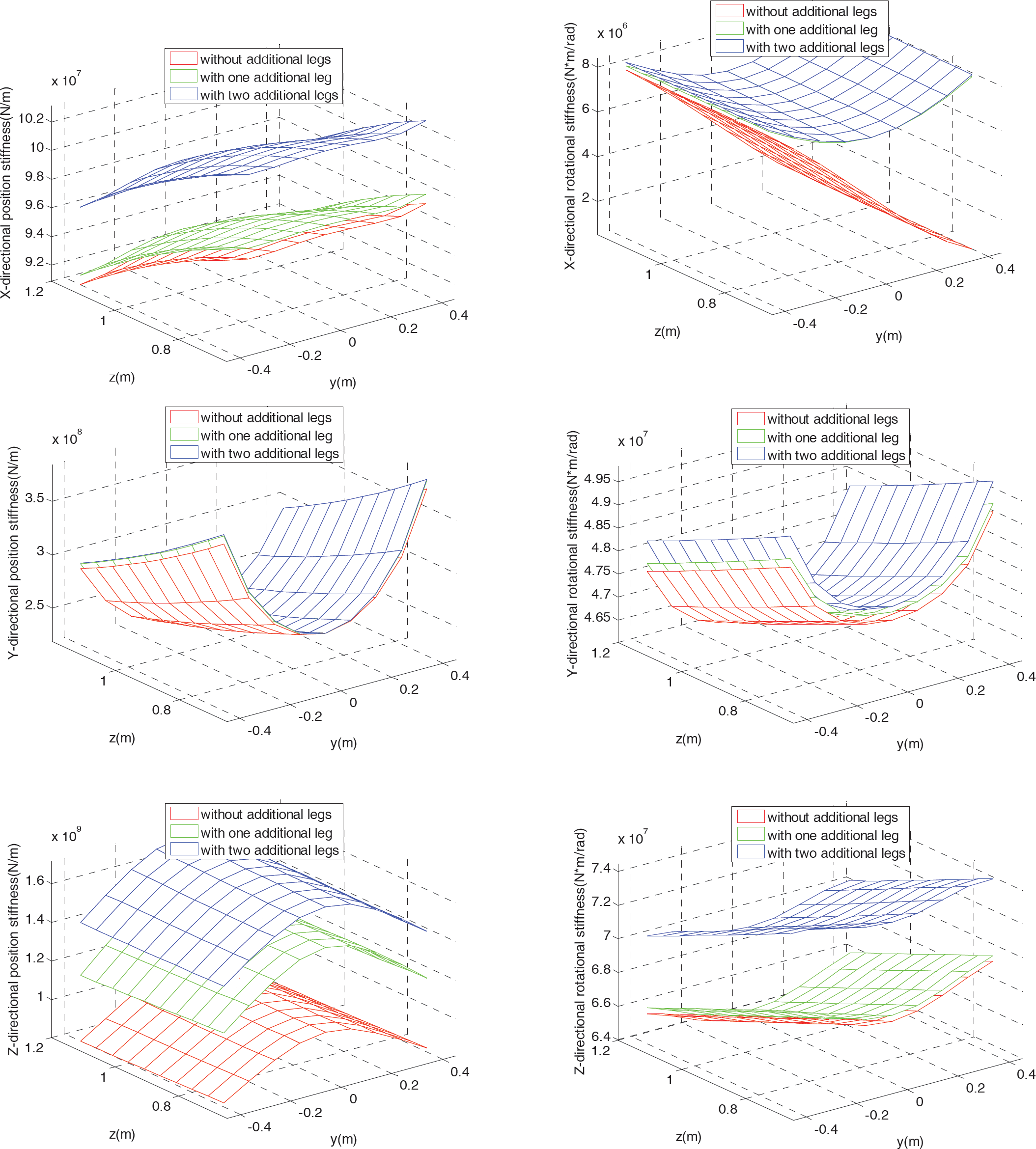
Comparison result with zero/one/two additional legs
To explicitly compare the stiffness of the 3-DOF parallel manipulator with zero/one/two additional legs, two evaluating indices are defined: the mean stiffness in the workspace (denoted as hk1) and the ratio of the difference between the maximum stiffness and the minimum stiffness to the maximum stiffness (denoted as hk2). hk2 can be expressed as

where kmax and kmin are the maximum stiffness and the minimum stiffness in the workspace, respectively [22].
Table 3 shows hk1 and hk2 of the planar parallel manipulators with zero/one/two additional legs with y ∊ [–400mm, 400mm], z ∊ [700mm, 1150mm], and a = 0°.
hk1 and hk2 of planar parallel manipulators

From Table 3, one may see that the Z-directional average position stiffness of the manipulator with zero/one/two additional legs is higher than the X-directional and Y-directional average position stiffness, and the X-directional average position stiffness is the lowest. The ratio of the difference according to the maximum stiffness and the minimum stiffness in the Y-directional and Z-directional position stiffness is greater than that in the X-directional position stiffness.
According to the value of hk1 from Table 3, the mean rotational stiffness in the X direction is the lowest among the X-directional, Y-directional and Z-directional rotational and position stiffnesses. Moreover, the ratio of the difference according to the maximum stiffness and the minimum stiffness in the X-directional rotational stiffness is the greatest. Thus, the X-directional rotation stiffness of the 3-DOF parallel manipulator with zero/one/two additional legs reflects the stiffness performance of the parallel manipulator, since the stiffness of a manipulator is determined by the lowest stiffness. Compared with the parallel manipulator without additional legs, the X-directional rotation stiffness of the 3-DOF parallel manipulator with one additional leg approximately doubled due to the one additional leg; the X-directional rotation stiffnesses of the 3-DOF parallel manipulator with one and two additional legs were similar. This means that the stiffness performances of the parallel manipulator with one/two additional legs are better than the manipulator without additional legs.
The stiffness model of a 3-DOF parallel manipulator with two additional legs is investigated. The condensation of degrees of freedom for the joint connection and the treatment of fixed ends for the fixed-end connections are taken into account. The stiffness of the manipulator with two additional legs is compared with that of the manipulator with zero/one additional legs. The X-directional and Z-directional position stiffnesses and Z-directional rotational stiffnesses of the manipulator with two additional legs are much higher than those of the manipulator with zero/one additional legs. The manipulator without any additional leg has the lowest stiffness among the three parallel manipulators. This modelling method can derive six-directional stiffness of a parallel manipulator. Moreover, the method is suitable for both redundantly actuated parallel manipulators and non-redundant parallel manipulators.
Acknowledgements
This work is supported by the National Natural Science Foundation of China (Grant No. 51105225, 51225503, 51375210), as well as a national grant for an excellent doctoral dissertation of PR China (201137), the National Science and Technology Specific Projects (2014ZX04002051, 2013ZX04000030), and the Fund of State Key Laboratory of Tribology (No. SKLT11C01).