
Abstract
A novel underwater long-arm manipulator (ULAM) and its improved small-flow hydraulic driving system (SHDS) are presented in this article for small autonomous underwater vehicle (AUV). In the process of manipulator design, a joint driving device consisting of linear hydraulic cylinder, three-bar linkage, and four-bar linkage mechanism is developed to allow the manipulator to be folded. Since the manipulator is much long, a small joint angle deviation would result in a large end-effector’s position deviation. To solve the problem, a small-flow hydraulic driving device with circulation in closed loop is proposed. And in the long-arm manipulator, the cross-sectional area of manipulator is small. So the diameter of hydraulic pipeline installed inside the manipulator is limited, but the pipeline should also be long enough. In this case, it is common to cause large pressure loss in hydraulic system. And, rather than oil, water is selected as the hydraulic medium due to the low viscosity. In the hydraulic system design, a scheme with circulation in closed loop and improved sealing structure (consisting of O-ring and Glyd-ring) are developed to reduce the internal leakage and maintain a good end-effector’s precision. In addition, the compressibility of water is relatively large, and it would bring bad impact on end-effector’s precision. In this case, the vacuum-treated water is used and it has a good performance in the high-pressure condition. But in the low-pressure condition, the problem is still serious. In order to solve the problem, based on the “vacuum treatment,” a pre-pressurization pressure treatment is added for the vacuum-treated water. All the improved ways are verified by experiment results. Finally, the end-effector’s positioning experiment and trajectory tracking experiment are conducted on manipulator and small AUV, so as to verify the effectiveness and feasibility of the ULAM.
Keywords
Introduction
Due to the land nonrenewable resources consumption at an alarming speed, the marine exploration has become more and more important and urgent. 1 Underwater equipment is required in this process. Currently, autonomous underwater vehicles (AUVs) operate autonomously in the complex and unknown underwater environment and have been widely applied in many tasks, including inspection of underwater structure, submarine rescue, underwater exploration, and so on. And the AUVs and underwater robotic vehicle play an irreplaceable role in the ocean development. 2 –5 Most of tasks require AUVs to have the ability to observe and to be able to operate in the ocean as well. 6 Interrupted by ocean currents, the AUVs could not approach too close to the target for their own security. So a long-arm manipulator is needed to approach the target. Meanwhile, in order to increase the voyaging performance of AUV, the manipulator is required to be stowed into AUV’s inner chamber to maintain a streamline outline. Therefore, this long-arm and foldable manipulator is designed in this article.
However, limited by the energy carried by an AUV, AUV’s volume, AUV’s weight, and so on, a manipulator mounted on an AUV is always driven by electronic motors. In TRIDENT EU FP7 project, an underwater electric manipulator was developed and equipped on multipurpose intervention-AUV. 7 An underwater electric manipulator (MARIS 7080, a 7 degrees of freedom robotic manipulator) was equipped on semi autonomous underwater vehicle for intervention mission (SAUVIM). 8 An electric manipulator with two degrees of freedom (DOFs) was installed on Twin-Burger AUV, a series of versatile test bed robots designed by University of Tokyo. 9 And an underwater electric manipulator with three functions was designed by the Shenyang Institute of Automation in China. 10
Recently, some researchers investigated long-arm manipulators. A long reach multi-articulated manipulator for EAST flexible in-vessel inspection system was proposed by Peng et al., 11 where the manipulator consisted of two rotary joints and four sliding joints and the joints were driven by actuator with harmonic drive gear box and so on. However, the size and weight of these joints are too large, inconvenient to be used in the small AUV. And, a 6-DOF manipulator with long arm and small cross section was designed by Chalfoun et al., 12 for the internal inspection of nuclear waste fuel facilities, where the joints were driven by the rope and pulley mechanisms. However, these joints cannot be folded and the control precision is poor, so this design also cannot be used in the small AUV.
Water-driven manipulator was developed by Kekäläinen et al., 13 to operate in radiation environment. In the manipulator, the joints were driven by swing cylinder and pump, and the position and force control were achieved by controlling the flow and pressure of water. Due to the size of the swing cylinder is much large, but the provided torque is relatively small, and the larger flow of the water hydraulic system in the study by Kekäläinen et al. 13 , this kind of driving mechanism is not suitable for the manipulator joint drive in this article. However, the volume of water hydraulic system is large, and it does not meet the requirement of micro-AUV system.
Based on the abovementioned analysis, a long-arm hydraulic manipulator and its driving device are investigated in this article.
In our project, it is required that the full length of underwater manipulator can reach above 2.0 m (the length of small AUV is 2.0 m). And in order to maintain a streamline outline in AUV, the manipulator should be foldable and stowed in the bottom of AUV. Due to the long-arm feature, large torque should be provided by joints. If selecting motor-driving mode, it would have many problems, including space and dynamic sealing issues. The motor shall combine with the torque amplification mechanism and dynamic sealing structure, all of these would occupy large space, unsuitable for the manipulator to be stowed in a small AUV. However, the hydraulic driving mode can generate high torque easily. And the power is transmitted to the manipulator through the hydraulic medium, not involved with dynamic sealing issues. In addition, the size of the hydraulic driving mechanism is small, convenient for storage into the AUV. Therefore, the hydraulic driving mode is chosen in this article.
At present, the hydraulic manipulator is mainly equipped on remotely operated vehicles (ROV) 14 or manned submersibles. Due to the advantages of high flexibility, heavy load, and large operating depth, the hydraulic manipulators have been widely used in exploration of marine, such as sampling of minerals and wrecking rescue. For example, a seven-function master–slave type underwater hydraulic manipulator is mounted on an ROV. 15 A deep-sea (7000 m) hydraulic manipulator system was developed for “Jiao-long” human-occupied vehicle. 16 The Orion 7P underwater hydraulic manipulator was investigated in Schilling Robotics (Davis, CA, USA). 17 The main control mode of hydraulic manipulator is implemented based on master–slave control. It has some disadvantages, including high energy consumption, high working pressure, and heavy weight. From the abovementioned consideration, it is necessary to research a long-arm and foldable underwater manipulator based on hydraulic-driven mode for small AUV.
In addition, the pressure of hydraulic system is one of the important content in this article. Due to the arm span of manipulator, in this article, is longer, resulting in the pipeline of hydraulic circuit of each joint longer (about 4.5 m); meanwhile, the manipulator folding volume is smaller, which leads to a smaller diameter (only 4 mm) of the hydraulic circuit. As for this long but thin pipeline, the pressure loss is very large when adopting water–glycol as hydraulic medium. In order to reduce the pressure loss, water is selected as medium. Although it has a good result in terms of reducing pressure loss, but the tracking performance driven by water is poor. And the tracking performance directly depends on hydraulic pressure in this article. In order to improve the tracking performance, the “vacuum + pre-pressurization” treatment is investigated.
In order to test the motion performance of underwater long-arm manipulator (ULAM), the trajectory tracking experiment of manipulator is carried out and the motion performance is verified by trajectory tracking accuracy. In practical, for the target trajectory tracking, the researchers mainly focus on the trajectory tracking control of AUV or ROV. 18 –21 Among them, in the study by Wang et al., 18 the global asymptotic model-free trajectory-independent tracking of underwater vehicle under the unknown dynamics and disturbances to any unmeasurable trajectory, an adaptive universe-based fuzzy control method with retractable fuzzy partitioning is proposed. The problem of steering AUV along a desired horizontal trajectory tracking control throughout the full-range low-speed and high-speed profiles was addressed by Xiang et al., 21 and they also studied the smooth continuous trajectory control transition between two configurations of the fully actuated and under-actuated AUV. The properties of the control objects (AUV or ROV) in the above literature belong to a class of model uncertain nonlinear systems, 22,23 and the ULAM also belongs to the model uncertain nonlinear system. Therefore, in this article, the trajectory planning and tracking method mentioned above is used as reference information for the trajectory tracking of manipulator.
The main research contents/contributions of the ULAM are presented as follows. In “Manipulator structure and its joint driving mechanism” section, a joint driving device consisting of linear hydraulic cylinder (LHC), a three-bar linkage mechanism, and a four-bar linkage mechanism is developed to allow the manipulator to be folded. Since the manipulator is much long, a small joint angle deviation would result in a large end-effector’s position deviation. In order to solve the problem, a small flow hydraulic driving device with circulation in the closed loop is proposed in “Development of hydraulic driving system” section. In terms of pressure loss, water, rather than oil, is selected as the hydraulic medium due to the low viscosity of water. In the hydraulic system design, a scheme with circulation in the closed loop and improved sealing structure (consisting of O-ring and Glyd-ring) are developed (in “Pressure loss of hydraulic system and its improved methods” section) to reduce the internal leakage and maintain a good end-effector’s precision. In addition, the compressibility of water is relatively large, and it would bring bad impact on the end-effector’s precision. In this case, the vacuum-treated water is used as medium and it has a good performance in the high-pressure condition. But in the low-pressure condition, the problem is still serious. In order to solve the problem, the pre-pressurization pressure treatment is added for the vacuum-treated water in “Driving performance of SHDS” section.
Finally, the end-effector’s positioning experiment and trajectory tracking experiment are conducted in “Experiments verification” section on our developed manipulator and small AUV, so as to verify the effectiveness and feasibility of the developed ULAM.
Manipulator structure and its joint driving mechanism
In this section, the joint driving mechanism will be designed. Based on the driving mechanism, the manipulator structure is presented.
Technical indexes of the ULAM
The ULAM technical indexes are presented as follows. The arm span of the ULAM can reach above 2.0 m. The ULAM arm can be folded step-by-step, and it can be fully stowed in AUV’s chamber; the range of the joint rotation angle is 0° to 180°. The maximum joint driving torque is greater than 10 kgf·m, the joint angular velocity range is 0° s−1–6.0° s−1, and the allowing pressure in the hydraulic system is less than 5 MPa. When AUV is fixed, the positioning accuracy of end-effector is less than ±5.0 mm. When AUV is in dynamical positioning condition, the end-effector’s tracking accuracy is less than ±100.0 mm.
Joint driving mechanism
Manipulator overall structure
The manipulator design should satisfy the functional and technical requirements at first. According to the technical indexes, and the ability to be foldable, a suitable joint number and the distribution of DOF will be designed to meet the functional requirements of manipulator. Meanwhile, the flexibility of the manipulator and the expansion of workspace should be considered when planning the distribution of DOF.
Based on the above characteristics, in this article, all joints are rotation and the sliding joint is not considered. The designed manipulator has three DOFs and five joints, as shown in Figure 1. In order to effectively increasing the manipulator’s length and reduce the overturning moment in pitch after manipulator folds fully, the cervical joint and the shoulder joint close to AUV rotate along Z-axles. And in order to reduce the overturning moment in roll, elbow joint is placed in the middle of manipulator and the joint’s length could be reduced. With respect to the length of each joint, the closer to AUV, the longer the joint is, considering the length requirement and foldable feature.
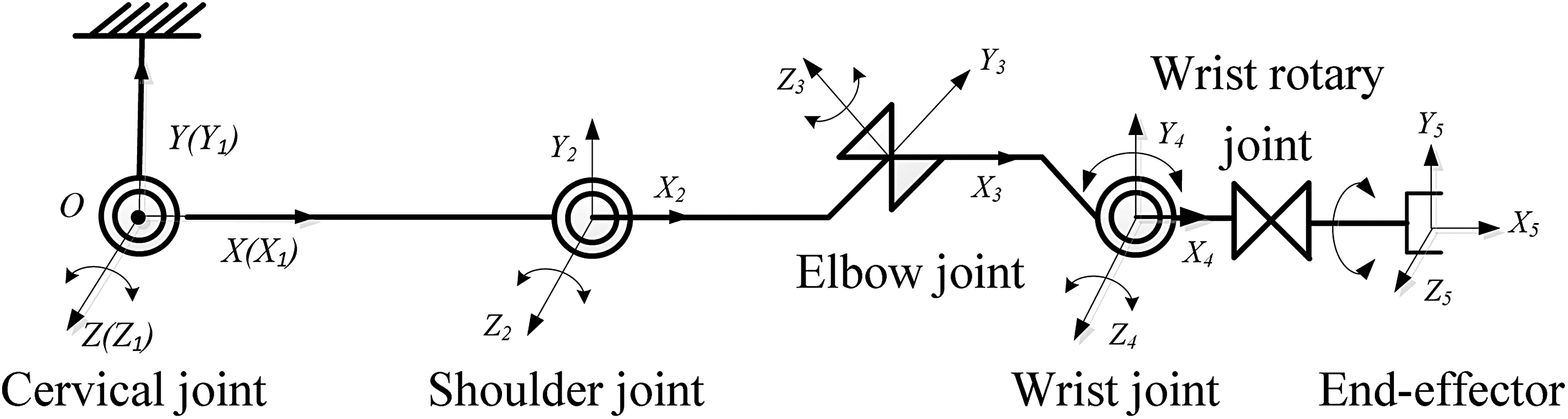
Mechanism diagram of the ULAM.
In Figure 1, the ULAM has five joints (cervical joint, shoulder joint, elbow joint, wrist joint, and wrist rotary joint) and end-effector (manipulator claw: grasping and shearing function). The wrist rotary joint (0° to 100°) and elbow joint (0° to 180°) rotate along X-axle and Y-axle and the other joints (0° to 180°) rotate along Z-axle.
In the process of joint driving mechanism, not only the operation range and driving torque but also the small volume and storable feature should be considered and satisfied at the same time. Due to the advantages of small size and simple control, hydraulic swing cylinder (HSC) is first considered. The HSC’s rotation angle can be up to 270°. And since the wrist rotation joint is the end of the manipulator, the joint needs relatively small torque. A small HSC could meet the requirement and allows the wrist rotation joint to be folded in the wrist joint. So HSC is suitable for the wrist rotation joint. However, the much large torques are required for other joints. If still selecting HSC, HSC with larger size should be selected to meet the torque requirement. In this case, it would be difficult to be folded and stowed for the manipulator. So another new driving mechanism should be developed.
“LHC + three-bar linkage + four-bar linkage” driving mechanism
Considering the strong driving ability of the LHC, a new joint driving mechanism is proposed based on LHC, three-bar linkage mechanism, and four-bar linkage mechanism (in short, “LHC + three-bar linkage + four-bar linkage”). The mechanism diagram is illustrated in Figure 2.

“LHC + three-bar linkage + four-bar linkage” driving mechanism. LHC: linear hydraulic cylinder.
In Figure 2, DE is the LHC, Ma is the mechanism driving torque, and ECO and OA are the arm. The DE drives the DBC (three-bar linkage) and BAOC (four-bar linkage), converting the linear motion into rotary motion, then drives ECO and OA to rotate mutually. Through the motion analysis of driving mechanism in Figure 2, the center of motion axis is point O, and the joint rotary angle is θ1. Based on mechanism simulation analysis, the maximum angle of θ1 is 205.0°, satisfying the range requirement of the joint rotation angle.
Design of the joint driving device and experiment verification
In this section, the joint driving device is designed based on kinematics and technical indexes. After theoretical analysis, the experiment verification is given. (1) Theoretical analysis
According to the technical index (3), the maximum joint driving torque is greater than 10 kgf·m, the range of joint rotation is 0° to 180°, the joint angular velocity range is 0° s−1 to 6.0° s−1, and the allowing pressure in the hydraulic system is less than 5 MPa. Considering the driving principles of the cervical joint, shoulder joint, elbow joint, and wrist joint are identical, the cervical joint is used as an example to analyze.
Based on the technical indexes of maximum pressure, the dimension and size of the hydraulic circuit, hydraulic cylinder, and other hardware are designed. According to the “LHC + three-bar linkage + four-bar linkage” mechanism in Figure 2, the kinematics analysis is performed in Pro/Engineer 5.0 software (developed by PTC company in USA). In kinematics simulation, the range of joint rotation is 0° to 205° and there is no motion interference. The results show that the designed mechanism satisfies the range requirement of the joint rotation angle.
With respect to the rotation speed requirement, it involves with hydraulic flow, it will be demonstrated in “Flow analysis of hydraulic system” section. (2) Experiment verification
In order to verify the effectiveness of the “LHC + three-bar linkage + four-bar linkage” driving mechanism, a joint of the ULAM (cervical joint, requiring the largest driving torque, is shown in Figure 3) was used to conduct experiments. And the torque experiment results (the relationship between driving torque and pressure) are shown in Figure 4.

Cervical joint of the ULAM.
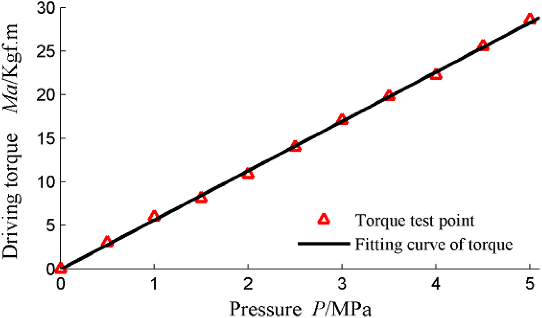
The relationship curve between LHC pressure P and driving torque Ma. LHC: linear hydraulic cylinder.
In Figure 4, the pressure of the LHC is 1.7 MPa and the joint driving torque (Ma) is larger than 10 kgf·m. Under the maximum pressure of 5.0 MPa, the joint driving torque (Ma) is 28.37 kgf·m, far larger than the requirement (10 kgf·m). In addition, the angle range is 0° to 202.582° measured by joint angle sensor, achieving the design purposes (in technical index (2)).
Stiffness analysis for the manipulator
Due to the large length of the manipulator, its stiffness would directly affect the accuracy of the end-effector. Therefore, this subsection is to analyze the stiffness of the manipulator, including the deformation and distribution of stress based on simulation.
Considering the density of aluminum alloy section is relatively small, and its strength is large, the material of 2A12 is used for the manipulator, and the frame structure is adopted. After designing the manipulator in 3D software, the deformation and distribution of stress are obtained based on the ANSYS software, as shown in Figure 5(a) and (b). In simulation, the weight of the manipulator is 10 kg (the real weight, calculation by the manipulator’s structure and material) and the load on the end-effector is 1 kg (requirement in the project).

(a) Overall deformation of the manipulator (unit: mm) and (b) stress distribution of the manipulator (unit: MPa).
From Figure 5(a), the maximum deformation of the end-effector is 0.873 mm, accounting for 8.73% of the allowing positioning error (±5 mm, the technical index (4)) when AUV is fixed. Compared with the allowing positioning error, the deformation is relatively small and it is continent for the controller to meet the technical index (4).
From Figure 5(b), the maximum equivalent stress is 55.2 MPa, far less than the tensile strength limit (472 MPa) and the yield limit (325 MPa) of the material (2A12). It demonstrates that the designed manipulator can satisfy the stiffness requirement.
Overall structure of the ULAM
Based on the mechanism diagram (in Figure 1) and joint mechanism, the overall structure of the ULAM is shown in Figure 6 and the folded structure is shown in Figure 6(b).
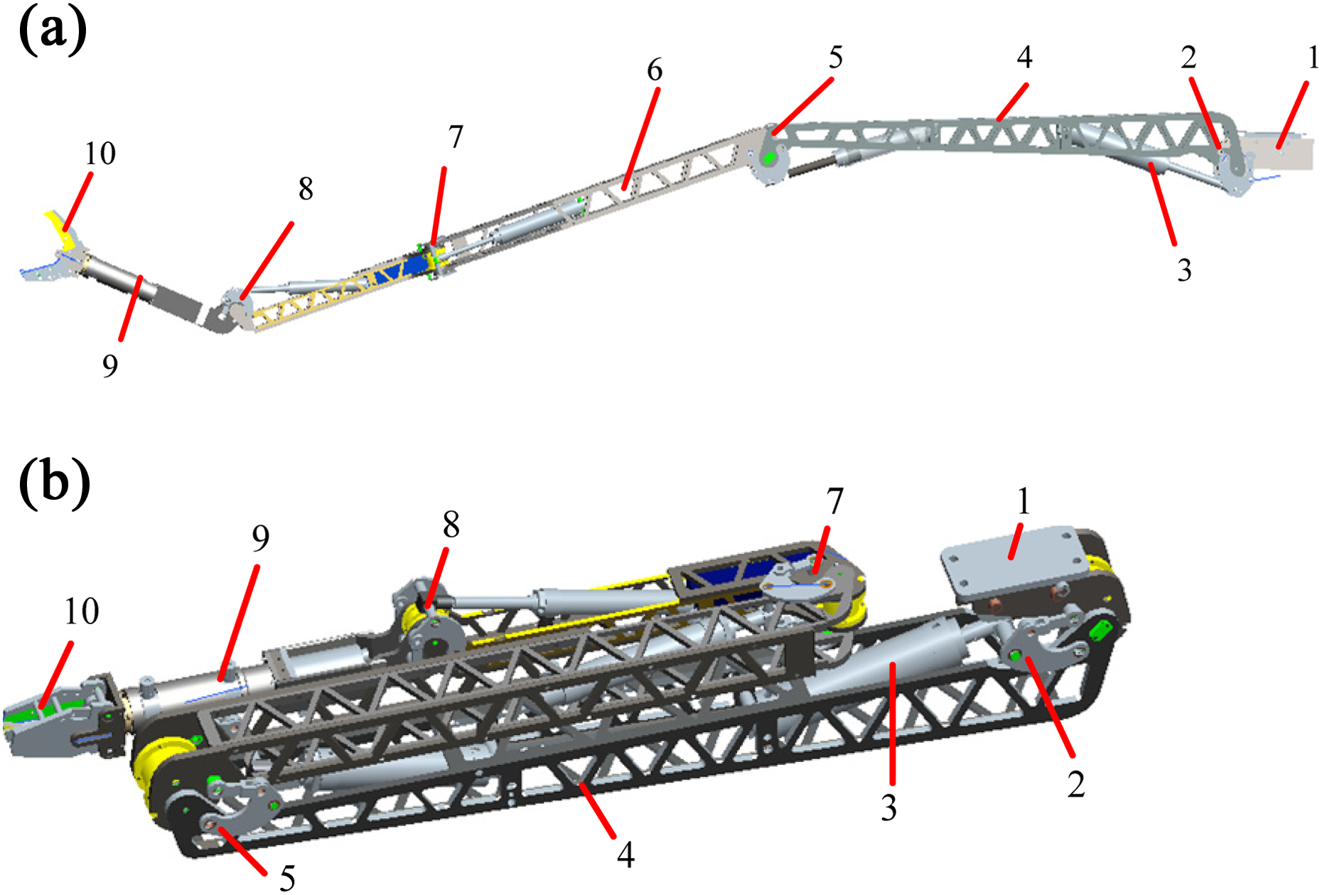
Overall structure of the ULAM. (a) Deployable structure and (b) fully folded structure. (1: mounting base; 2: cervical joint; 3: LHC; 4: manipulator arm; 5: shoulder joint; 6: hydraulic pipeline; 7: elbow joint; 8: wrist joint; 9: wrist rotary joint; 10: end-effector.) LHC: linear hydraulic cylinder.
In Figure 6, the cervical joint, shoulder joint, elbow joint, and wrist joint are driven by the same “LHC + three-bar linkage + four-bar linkage” mechanism structure, and the wrist rotary joint is driven by HSC mechanism. The manipulator arm is in frame structure. The folded manipulator can be stowed into the bottom of small AUV. In Figure 6, the fully extended ULAM can reach 2.38 m (arm span of manipulator) and the movement range of end-effector in X axle, Y axle, and Z axle is (−1000, 2380) mm, (−2380, 0) mm, and (−350, 800) mm, respectively. The designed manipulator can be folded and stowed in the AUV bottom. In addition, the developed “LHC + three-bar linkage + four-bar linkage” driving mechanism can guarantee that the designed manipulator can satisfy the requirements. The designed driving mechanism provides a new idea for the foldable manipulator design.
Hydraulic driving method of the ULAM
To achieve the high positioning accuracy of end-effector in technical index (4) and be conveniently carried by a small AUV, a small-flow hydraulic driving method is investigated in this section.
Development of hydraulic driving system
Flow analysis of hydraulic system
Due to the manipulator’s multi-DOF and long-arm features, the small deviation of each joint would cause large end-effector’s position deviation. For example, a 0.1° rotational error of cervical joint can generate a 4.0-mm end-effector’s position deviation, if there are no other angle deviations in other joints. During the actual operation of the ULAM, the end-effector’s positioning error can be compensated by a good control algorithm, but improving the “design precision” of the hydraulic system in design stage is beneficial to the high precision control of the manipulator.
Theoretically, the positioning accuracy of end-effector of ULAM is determined by the joint rotation accuracy, which depends on the flow control accuracy. As a consequence, improving the flow control accuracy of hydraulic system can gain a higher positioning accuracy of end-effector.
Next, analyze the flow in the hydraulic system. Except wrist rotation joint, the driving principle of other joints is identical. So the cervical joint is used as an example to conduct flow analysis. According to the joint angular speed requirement (0° s−1 to 6° s−1), the volume of LHC of cervical joint (125.6 mL), and the joint rotation angle range (0° to 180.0°), it is calculated that it requires 0.698 mL liquid to drive the joint to rotate by 1°. Therefore, according to the angular speed requirement (0° s−1 to 6° s−1), the theoretical flow quantity range is 0–0.25 L min−1.
Design of SHDS
From the abovementioned analysis, the theoretical flow quantity range of hydraulic system is 0–0.25 L min−1 and the maximum pressure of hydraulic system is 5.0 MPa. There are no available commercial miniature hydraulic pump products 24,25 to satisfy the above specifications. The maximum flow quantity of piezoelectric pump in the study by Li et al. 26 is up to 1.08 L min−1, but its maximum output pressure is only 0.344 MPa. The small water-hydraulic pump (Danfoss APP1.0-2.2, a high pressure pump produced by Danfoss company in Denmark) in the study by Drabløs 27 could reach the maximum pressure, but its maximum allowable flow quantity is 2.4–16.7 L min−1, far larger than the range (0–0.25 L min−1). To sum up, a small-flow hydraulic driving system (SHDS) should be developed by ourselves, so as to be suitable for the ULAM.
Based on the above analysis, inspired by the microinjection pump 28 in pharmaceutical industry, a hydraulic novel driving method is developed based on DC servomotor, screw-nut pairs, and LHC. And the structure principle of SHDS is presented in Figure 7.

The small-flow hydraulic driving system. (a) Principle diagram of SHDS and (b) physical photos of SHDS. (1: servomotor; 2: screw-nut pairs; 3: master hydraulic cylinder; 4: hydraulic pipeline; 5: slave hydraulic cylinder.)
In Figure 7, the SHDS is composed of two parts: the hydraulic power source located in a small AUV and the slave hydraulic cylinder installed in the manipulator. And the two parts are connected through hydraulic pipeline. In Figure 7(a), through the screw-nut pairs, it converts the rotation motion of servomotor into linear reciprocating motion of master hydraulic cylinder. The hydraulic power of master hydraulic cylinder is transferred to the slave hydraulic cylinder through the hydraulic medium in pipeline. Then, through the “LHC + three-bar linkage + four-bar linkage” driving mechanism, the slave hydraulic cylinder fixed on the joint can be rotated.
In this article, the hydraulic medium of SHDS is in the closed pipelines, forming the “closed loop” hydraulic system. To decrease the leakage of hydraulic system, the sealing structure with O-ring and Glyd-ring is adopted in these cylinders.
Figure 7 shows the SHDS for the single joint. And each joint and end-effector has a similar and independent SHDS. From the design perspective, the SHDS has the following features. The “closed loop” hydraulic system, it does not need an oil tank, reducing the weight and volume of hydraulic system. The driving components, such as servomotor and screw-nut pairs, were installed inside the SHDS. And the hydraulic power is transmitted through hydraulic medium in the “closed loop” hydraulic pipeline, avoiding the dynamic sealing issue. The motion of ULAM joint is controlled by the servomotor. And the angular velocity can be adjusted by motor speed. These improvements simplify the joint control. The screw-nut pairs with large reduction ratio can amplify the output torque of the servomotor. The screw-nut pairs have the self-locking ability, allowing the position–gesture of the ULAM to be maintained even if motors stop. It reduces energy consumption.
Analysis about the relationship between the manipulator accuracy and hydraulic pressure
The positioning accuracy of end-effector is one of the important indexes. In order to satisfy the index, it needs to find and investigate the factors about the index. After determining the structure of manipulator, hydraulic driving method, and other hardware, the main factors that could influence the positioning accuracy of end-effector are flow speed and pressure. Due to the range of the flow speed is very small (analysis in “Flow analysis of hydraulic system” section), it has a little impact on the accuracy. Therefore, this subsection is to analyze the relationship between the manipulator accuracy and hydraulic pressure from the theoretical viewpoint.
The dynamics of the manipulator and control method are the main factors influencing the positioning accuracy of end-effector. In this article, the control method is not the main content. The dynamics of the manipulator mainly depends on the driving torque acting on the manipulator joint. And the driving torque depends on the hydraulic pressure and the action area. After determining the structure of manipulator, the action area is fixed. Therefore, the torque acting on joint depends on the hydraulic pressure. In other words, the hydraulic pressure becomes the main factor in this article.
Next, it will analyze the relationship between the manipulator accuracy and hydraulic pressure. When the hydraulic medium flows through long and thin pipeline, serious pressure is wasted by the frictional resistance of the hydraulic medium inside the pipeline. And the pipeline pressure loss is proportionate to the viscosity of the hydraulic medium, after determining the hydraulic system principle and pipeline length. In addition, liquid compressibility is related to hydraulic pressure and the relationship between compressibility and hydraulic pressure is nonlinear.
Based on the abovementioned analysis, there exists a strong nonlinearity relationship between the pressure and the positioning accuracy of end-effector. It is also very difficult to derive a mathematical model to reflect the relationship. Therefore, we will investigate the relationship according to experiments and find the ways to improve the accuracy.
Pressure loss of hydraulic system and its improved methods
In this article, the arm span of manipulator has a long length (2.3 m) and the average length of hydraulic pipeline (in Figure 7) is about 4.5 m. And it also requires a smaller folding volume of manipulator, so it makes the cross-sectional area of the manipulator arm smaller, this resulting in a smaller diameter (about 4 mm) of the hydraulic pipeline. The above factors cause the hydraulic pipeline to be long and thin. At first, to reduce environment pollution, water–glycol was firstly selected as medium. But the viscosity of water–glycol is relatively large. When it flows through long and thin pipeline, a serious pressure is wasted by the frictional resistance of the hydraulic medium inside the pipeline. So in this section, the impact that pressure loss would have on the tracking performance of manipulator joints and its improved method are investigated.
Pressure loss experiment
Due to the medium state is difficult to determine in the long and thin pipeline, 29 and the accurate pressure loss cannot be obtained from theoretical analysis, a pressure loss experiment is carried out in the SHDS, as shown in Figure 8. And sensors are used to measure the pressure at different points.

The principle diagram of pressure loss experiment device.
In Figure 8, the diameter of hydraulic pipeline is 4.0 mm and total length is 4.55 m (the real length in our project). The water–glycol is selected as hydraulic medium. The pressure sensors measure the outlet pressure (P1) of master hydraulic cylinder and the entrance pressure (P2) of slave hydraulic cylinder. Recording the pressures P1 and P2, the pressure difference (P1 − P2) is the pipeline pressure loss of SHDS. The experiment results are shown in Figure 9.
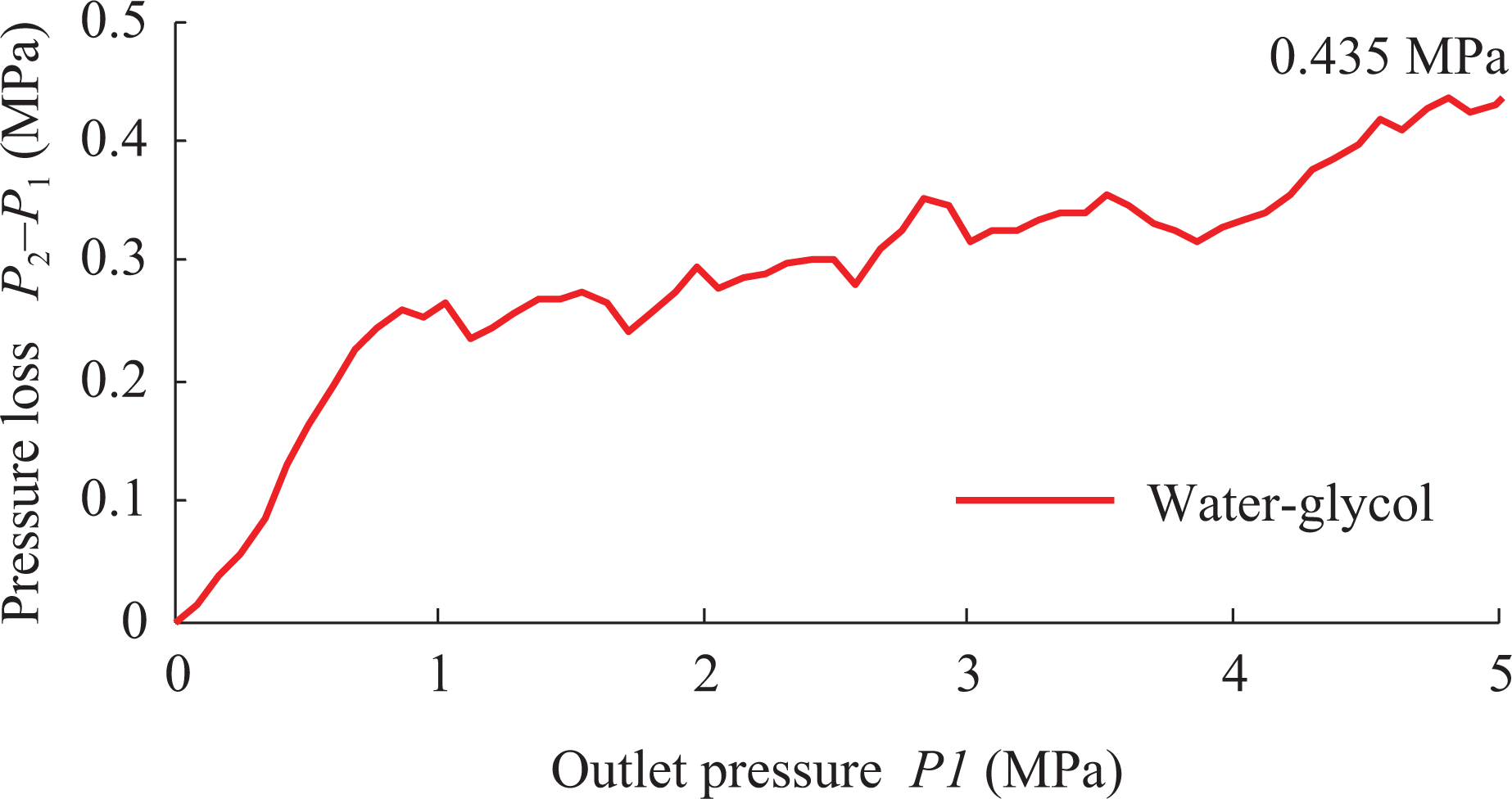
The pressure loss of water–glycol.
Based on the data in Figure 9, when P1 is in the range of 1.0–4.0 MPa, the pressure loss (P1 − P2) is about 0.3 MPa. When P1 is under the pressure of 5.0 MPa (the maximum allowing pressure in the project), the maximum pressure loss is about 0.435 MPa.
Normally, the working pressure of ULAM is 1.0–4.0 MPa. From Figure 4, the pressure loss (0.3 MPa) would lose 2.1 kgf·m in this case. And compared with the torque required of 10 kgf·m (technical index (3)), the torque loss ratio is about 21%, directly affecting the driving performance of the SHDS. To solve the problem, the following improvements are proposed in “Improved method of pressure loss” section.
Improved method of pressure loss
Analyze the cause of pipeline pressure loss. After determining the hydraulic system principle and pipeline length, the pipeline pressure loss is proportionate to the viscosity of the hydraulic medium. 30 To reduce the pressure loss, water was selected as the hydraulic medium because of its lower viscosity. And due to the advantages of low cost, easy water-medium handling, and flame retardant, water is very suitable for the hydraulic manipulator system in this article. 31
To verify the effectiveness in terms of the pressure loss, the pressure loss experiment is conducted again, but this time, the medium is changed as water. Under the same conditions of pressure, the pressure loss of water is shown in Figure 10.

The results of pipeline pressure loss.
In Figure 10, the pressure loss (P1 − P2) increases slightly as the pressure P1 increases. When P1 is in the range of 1.0–5.0 MPa, the maximum pressure loss (P1 − P2) is about 0.05 MPa. From Figure 4, a 0.05-MPa pressure loss will generate a 0.29 kgf·m manipulator driving torque loss. Compared with the torque required of 10 kgf·m (technical index (3)), the torque loss ratio is about 2.9%. The result from Figure 10 shows that water medium can reduce the pressure loss by 88.51% compared with the water–glycol and the torque loss decreases from 2.1 kgf·m to 0.29 kgf·m. The experiment results validated water is better choice in terms of reducing pressure loss.
Water-medium leakage issue
Due to the low viscosity of water medium, the leakage of hydraulic system must be considered when using water as the hydraulic medium. The leakage experiment of water medium was conducted in this section; the principle diagram of experiment is shown in Figure 11.

Principle diagram of water-medium leakage experiment. (1: master hydraulic cylinder; 2: slave hydraulic cylinder; 3: piston of hydraulic cylinder; 4: external workload.)
The experimental procedures of measuring water-medium leakage are as follows. At t = 0 s, the manipulator joint was driven by SHDS, and then stop at 72.088°. At t = 120 s, a 10 kgf·m of external workload was applied to the manipulator joint (at point A in Figure 11, the direction of the external workload is downward), and it would be maintained till t = 540 s. At t = 540 s, unloading the external workload.
During the whole experiment process (0–720 s), the piston of slave hydraulic cylinder slightly moved under the external workload, resulting in the manipulator joint angle (θ1 in Figure 11) variation, as shown in Figure 12. To analyze the leakage situation, the relevant data are collected from Figure 12, as shown in Table 1.

Variation curve of the manipulator joint angle (θ1).
Variation value of manipulator joint angle (θ1).

From Table 1: During 0–120 s, there is no external workload on the joint and the joint angle remains 72.088°, indicating no leakage in 0–120 s. At t = 120 s to 122 s, a 10 kgf·m workload is added to the joint. In 2 s, the angle varies from 72.088° to 71.991°, and finally remains 71.991° (the angle variation: −0.097°). During 122–540 s, the manipulator joint angle remains 71.991°, indicating no external leakage and internal leakage in SHDS.
Based on the above analysis, if the internal leakage exists, it must occur in the loading moment (during 120–122 s). When unloading the 10.0 kgf·m workload (t = 540 s), the joint angle changes from 71.991° to 72.083° and then remains 72.083° (during 540–720 s). The joint angle does not return to its original angle (72.088°), indicating that the internal-leakage happens in 120–122 s.
Quantitatively analyze the internal leakage. The joint angle deviation is 0.005° (72.088° − 72.083° = 0.005°). The joint angle deviation (0.005°) will cause a 0.2-mm positioning error of end-effector. This deviation is much small, compared to the allowing positioning error. It indicates that internal leakage has little impact on the positioning accuracy of end-effector.
Next, it will analyze the influencing factors of the internal leakage. When water is used as hydraulic medium, the internal leakage is mainly caused by the small viscosity of medium. However, the viscosity is related to temperature, pressure, and air content. But in SHDS, the changes of temperature and pressure are small. Therefore, the main influencing factors of the medium viscosity are air content in water medium. The air exists in water with two forms: one is dissolved in water medium; the other is suspended in water medium in the form of bubble. The air dissolved in water has little influence on the viscosity. Hence, the presence of air in the form of bubbles has a great influence on the viscosity of water medium. Thus, the bubbles in water medium are the main factor affecting the internal leakage. In this article, the “vacuum treatment” method is adopted in “Single joint’s trajectory tracking experiment after ‘vacuum treatment’” section to reduce the internal leakage and improve the driving performance of SHDS.
To sum up, when water is selected as hydraulic medium of SHDS, pressure loss of hydraulic system issues can be effectively reduced. Although the leakage exists, it is too tiny to affect the positioning accuracy of end-effector. But in order to avoid corrosion to the inner components, 3Cr13 stainless steel material is used to manufacture these components of the LHC, the master cylinder, the slave cylinder, and the piston. In addition, the distilled water is used as the water medium of the “closed loop” hydraulic pipeline to reduce corrosion.
Driving performance of SHDS
Single joint’s trajectory tracking
In this subsection, in order to test the motion performance of manipulator joint, the single joint’s trajectory tracking experiment is performed on the developed SHDS and cervical joint in the pool condition.
The pressure of each joint depends on the task and joint motion. To fully test the driving performance of SHDS, the tracking experiments are performed in two different pressures (high pressure 4.0 MPa and low pressure 1.5 MPa). The desired trajectory is a “sine curve” with 20° amplitude and 0.025 Hz frequency. fuzzy- proportion integral derivative control (PID) algorithm is applied to control the joint. The tracking results are shown in Figure 13 and Table 2.

The sine curve tracking performance of the ULAM joint. (a) Trajectory tracking curve and (b) trajectory tracking error.
The experimental results of trajectory tracking.
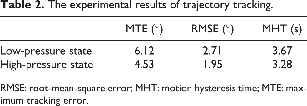
RMSE: root-mean-square error; MHT: motion hysteresis time; MTE: maximum tracking error.
From Table 2, in these two conditions, the maximum tracking error (MTE) of the manipulator joint, the root-mean-square error (RMSE), and the motion hysteresis time (MHT) are relatively large. But the results in the low-pressure condition are worse than those in high-pressure condition.
According to the above experiment results, the pressure condition is an important factor to affect the tracking accuracy of the manipulator. And compared with the result in high-pressure condition, the tracking accuracy is worse in the low-pressure condition. However, the value of the trajectory tracking error is large, which does not meet the needs of manipulator operation. The reasons for the larger tracking error are as follows.
The numerous air bubbles are contained in water medium and the bubbles are the main factor which caused the internal leakage in SHDS. And also the bubbles can be easily dissolved and compressed by ambient pressure. That means the volume of the water would decrease under the pressure in SHDS, namely the liquid compression. 32 In SHDS, the joint rotation depends on the translation of the slave hydraulic cylinder. Due to the great compressibility of the water medium, the slave hydraulic cylinder starts to move till the compression limit of water reaches, and then the joint start to rotate. The above process will lead to tracking error and motion hysteresis of manipulator joints. Therefore, according to the above analysis, the bubbles are the primary cause of tracking error and motion hysteresis, when water is selected as the hydraulic medium.
Single joint’s trajectory tracking experiment after “vacuum treatment”
Based on the above analysis, to reduce the tracking error and MHT, the number of bubble in water should be reduced. And the most common way is “vacuum treatment.”
In this article, the “vacuum treatment” is implemented by using vacuum pump to reduce the bubbles in the condition of negative pressure (0.08 MPa). After the “vacuum treatment,” the single joint’s trajectory tracking experiment was conducted again. In the same conditions, the results are shown in Figure 14 and Table 3.

The tracking performance after “vacuum treatment.” (a) Trajectory tracking curve and (b) trajectory tracking error.
The experimental results after “vacuum treatment.”
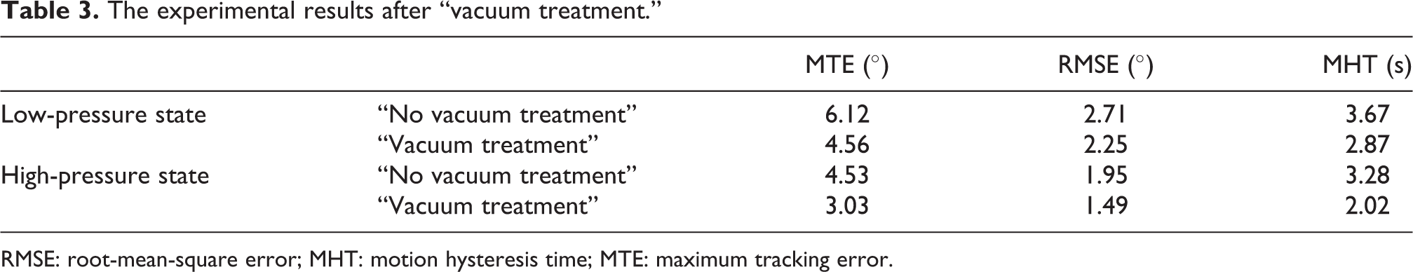
RMSE: root-mean-square error; MHT: motion hysteresis time; MTE: maximum tracking error.
In Table 3, compared with the “no vacuum treatment,” after “vacuum treatment,” the MTE, RMSE, and MHT are decreased by 33.12%, 23.59%, and 38.41%, respectively, in the high-pressure condition; and reduced by 25.49%, 17.01%, and 21.80%, respectively, in the low-pressure condition. The results show that the trajectory tracking performance is still poor in low-pressure condition, even after vacuum treatment.
The reasons of the poor tracking performance in low-pressure condition are shown as follows. The “vacuum treatment” can remove most of the bubbles in water, but there are still a small amount of bubbles in water. According to Henry’s law, 33 the dissolved quantity of air bubbles in water is smaller in low-pressure condition. So the amount of bubbles in the low-pressure condition is larger than that in high-pressure condition, causing that water can be still compressed in the low-pressure condition. As a result, the tracking performance is still poor in the low-pressure condition, even though the water is vacuum treated.
At last, analyze the influences the “vacuum treatment” would have on the accuracy of the end-effector from theoretical viewpoint. Due to the “vacuum treatment” remove most of the bubbles in water, it can increase the anti-compressibility of water medium. According to the last two paragraph of “Single joint’s trajectory tracking” section, the compressibility of water is the primary cause of tracking error and motion hysteresis; therefore, the “vacuum treatment” can improve the anti-compressibility, then it can reduce the tracking error of the manipulator joint and improve the positioning accuracy of end-effector.
Improvement method of the water-medium treatment
Based on the above analysis, to improve the tracking performance in the low-pressure condition, the pre-pressurization pressure treatment is added for the vacuum-treated water (in short, “vacuum + pre-pressurization” treatment).The essence of the method is to increase the initial pressure of water in SHDS, thereby increasing the dissolved quantity of bubbles in water, and finally reducing the compressibility of water medium. (1) Determination of pre-pressurization value
To determine the pre-pressurization value, the effective bulk modulus, 31,34 the evaluation index of anti-compression ability of liquids, is analyzed at first. Definition of the effective bulk modulus is given as follows 35

where E is the effective bulk modulus of water medium, V is the original water volume, and ΔP and ΔV are the change of water pressure and volume, respectively.
To calculate the effective bulk modulus of water, based on equation (1) and the bulk modulus definition, 36 the bulk modulus measure system is constructed, as shown in Figure 15.

Principle diagram of the bulk modulus measure device. (1: displacement sensor; 2: hydraulic pump; 3: switch valve; 4: unloading valve; 5: pressure sensor; 6: LHC; 7: test chamber.) LHC: linear hydraulic cylinder.
Take water in the test chamber 7 as an example to calculate the effective bulk modulus. The pressure is transmitted to test chamber through port A, and the pressure can be adjusted by the hydraulic pump. The sensor 1 is used to measure the variation of water volume.
Based on P–V curve obtained from above experiment, calculate the ΔP/ΔV, which is the tangent slope of P–V curve. And then the relationship between pressure P and effective bulk modulus E is obtained based on experiment data and equation (1), as shown in Figure 16.

Relationship curve between bulk modulus E and pressure P.
Under the condition of “vacuum treatment” or “no vacuum treatment,” the change trends of the effective bulk modulus E are similar from Figure 16. During 0–1.5 MPa, the effective bulk modulus E increases rapidly with the increase in pressure P. During 1.5–5.0 MPa, the effective bulk modulus E increases slowly. In conclusion, considering the maximum pressure of the SHDS (5.0 MPa), the pre-pressurization pressure is set as 1.5 MPa, that is, an initial pressure of 1.5 MPa is added in the pipeline of the SHDS. (2) Single joint’s tracking performance after “vacuum + pre-pressurization” treatment
To verify the joint driving performance after “vacuum + pre-pressurization” treatment method, the trajectory tracking experiments were conducted. The desired trajectory is the same as that in “Single joint’s trajectory tracking experiment after ‘vacuum treatment’” section. And the results are shown in Figure 17 and Table 4. Since the method of “vacuum + pre-pressurization” treatment is aimed to improve the tracking performance of low-pressure state, the trajectory tracking experiments were conducted only in the low-pressure condition.

The tracking performance in low-pressure state. (a) Trajectory tracking curve and (b) trajectory tracking error.
Tracking error and MHT after “vacuum + pre-pressurization” treatment.

RMSE: root-mean-square error; MHT: motion hysteresis time; MTE: maximum tracking error.
In Table 4, compared with “vacuum treatment,” after “vacuum + pre-pressurization” treatment, the MTE, RMSE, and MHT are reduced by 33.12%, 30.05%, and 38.41%, respectively. And the results validated the effectiveness of “pre-pressurization treatment.” After “vacuum + pre-pressurization” treatment, the MTE, RMSE, and MHT are decreased by 61.11%, 65.68%, and 60.49%, respectively, compared with the un-treatment condition.
Basically, after “pre-pressurization treatment,” the initial pressure of pipeline is 1.5 MPa, it would bring some negative impact on the driving performance of the hydraulic system. Without the “pre-pressurization” treatment in pipeline, the pressure range of the SHDS is 0–5.0 MPa. After “pre-pressurization” treatment, the pipeline of the SHDS has an initial pressure of 1.5 MPa; the maximum pressure of the SHDS, used to drive joint, reduced from 5.0 MPa to 3.5 MPa.
In conclusion, the “pre-pressurization treatment” improves the driving performance of the SHDS while reducing the maximum driving pressure. And according to Figure 4, under the pressure of 3.5 MPa, the driving torque of manipulator joint is up to 21.58 kgf·m, still satisfying the maximum joint driving torque requirement (technical index(3)).
Analyze the influences the “pre-pressurization treatment” would have on the accuracy of the end-effector from theoretical viewpoint. The “vacuum treatment” can remove most of the bubbles in water, but there are still a small amount of bubbles in water. After “vacuum treatment,” the water pressure could be enhanced further by the pre-pressurization treatment. In this case, the anti-compressibility of water is further increased and the accuracy of the end-effector is improved as well. In addition, in this article, the “vacuum + pre-pressurization” treatment is proposed to improve the tracking accuracy under the low-pressure condition. Actually, the anti-compressibility of water will be increased according to the “vacuum + pre-pressurization” treatment, no matter under low- or high-pressure condition. But the effect would be more obvious, compared with that in high-pressure condition. Therefore, the tracking accuracy is improved obviously in the low-pressure condition.
After “vacuum treatment,” the tracking performance is still poor in the low-pressure condition. The developed “vacuum + pre-pressurization” treatment can increase the anti-compressibility, but the effect would be more obvious in low-pressure condition. This method can reduce the tracking error of the joint, so the accuracy of the end-effector can be improved. This treatment could be considered in the water-driven system design, especially for improving the control accuracy in different pressures. In addition, it is difficult to determine the pre-pressurization value. The relationship between effective bulk modulus and pressure is obtained from experiment. According to the experiment data, the pre-pressurization value is determined. This method and the experiment could be applied to other water-driven system.
Flow quantity experimental verification of SHDS
This subsection is to verify the developed SHDS can also satisfy the requirement about flow quantity (0–0.25 L min−1). The flow quantity experimental process is shown as follows. Change the motor speed n to adjust the flow quantity Q and then measure the flow quantity Q inside the pipeline through flow sensors. The relationship between Q and n is shown in Figure 18.

The relationship curve between motor rotation speed n and flow quantity Q.
In Figure 18, when the motor rotation speed varies from 0 r min−1 to 25,000 r min−1, the flow quantity range measured by flow sensor is 0–0.31 L min−1 and 0–0.28 L min−1, corresponding to the forward rotation of motor and – the reverse rotation of motor, respectively. Both of them meet the flow quantity range (0–0.25 L min−1).The cross section of the right chamber and the left chamber of the LHC is different, making the flow quantity in the right chamber different from that in the left chamber. So there are differences between the forward rotation and the reverse rotation in terms of the flow quantity.
Experiments verification
The abovementioned experiments verified the performance of single joint and hydraulic system. To evaluate the overall motion performance of the underwater manipulator system, the joints and their small-flow hydraulic driving system are integrated to form the underwater long-arm hydraulic manipulator. Then, the manipulator is carried on a small AUV. At this time, the underwater vehicle manipulator is developed, as shown in Figure 19. In experiments, the control is implemented based on fuzzy-PID 37 algorithm.

The UVMS experimental platform. (a) Fully stowed state of the manipulator in small AUV, (b) manipulator expansion, and (c) underwater operation. AUV: autonomous underwater vehicle.
In this section, two kinds of experiments are performed. The first one is experiment for the positioning accuracy of the end-effector when AUV is fixed. The other one is the trajectory tracking experiment of the end-effector when AUV is in dynamical positioning condition. Since the application of our project is to cut the rope in the water, the end-effector does not carry other payload, and this article focuses on the positioning accuracy of the end-effector arriving at the rope.
Experiment for the positioning accuracy of the end-effector when AUV is fixed
In the pool environment, the AUV is fixed in the pool, namely AUV cannot move. The end-effector positioning experiment is conducted to demonstrate that the positioning accuracy of end-effector can meet the requirement of technical index (4) (less than ±5 mm).
The experimental procedures and sensors are given as follows. In the manipulator coordinate system O-XYZ (as shown in Figure 1), an arbitrary target-point A is given. Based on the target-point A, every target joint angle is calculated through the inverse kinematic equation. Rotate the joints of ULAM to joint target angle, and the actual joint angle is recorded from the joint angle sensor (Smartsyn-TS2605 resolver made in Japan, with 0.005° of the measurement resolution). According to the kinematics calculation of actual joint angle, the coordinate of actual-point B is obtained. Evaluating the deviation between A and B, then the positioning accuracy of end-effector is obtained.
The manipulator coordinate system O-XYZ is shown in Figure 1 and set the center of cervical joint as coordinate origin O. In experiment, the target-point A is (1380.5, −312.7, −151.5) mm, and the step responses of each joint angle are shown in Figure 20.

The step response curves of the manipulator joint angle.
The relevant data are collected from Figure 20, as shown in Table 5.
Step responses data of the manipulator joints.

In Table 5: Since the cervical joint is close to the AUV, it has the largest driving torque, so the angular velocity is relatively small. The elbow joint and wrist joint are installed far away from the AUV, and they just need small torques. So the joint angular velocity is relatively larger. The maximum overshoot and the maximum steady-state error are 2.23% and 0.042°, respectively, among all joints. The results show that the motion fluctuation of the manipulator is small and the control accuracy of joint angle is relatively higher.
The positioning accuracy of end-effector can be reflected by the index of end-effector’s positioning errors. 38 Other experiments are also conducted for positioning other target points. The end-effector’s positioning errors are presented in Table 6.
Other 15 groups experiment results of end-effector’s positioning error.
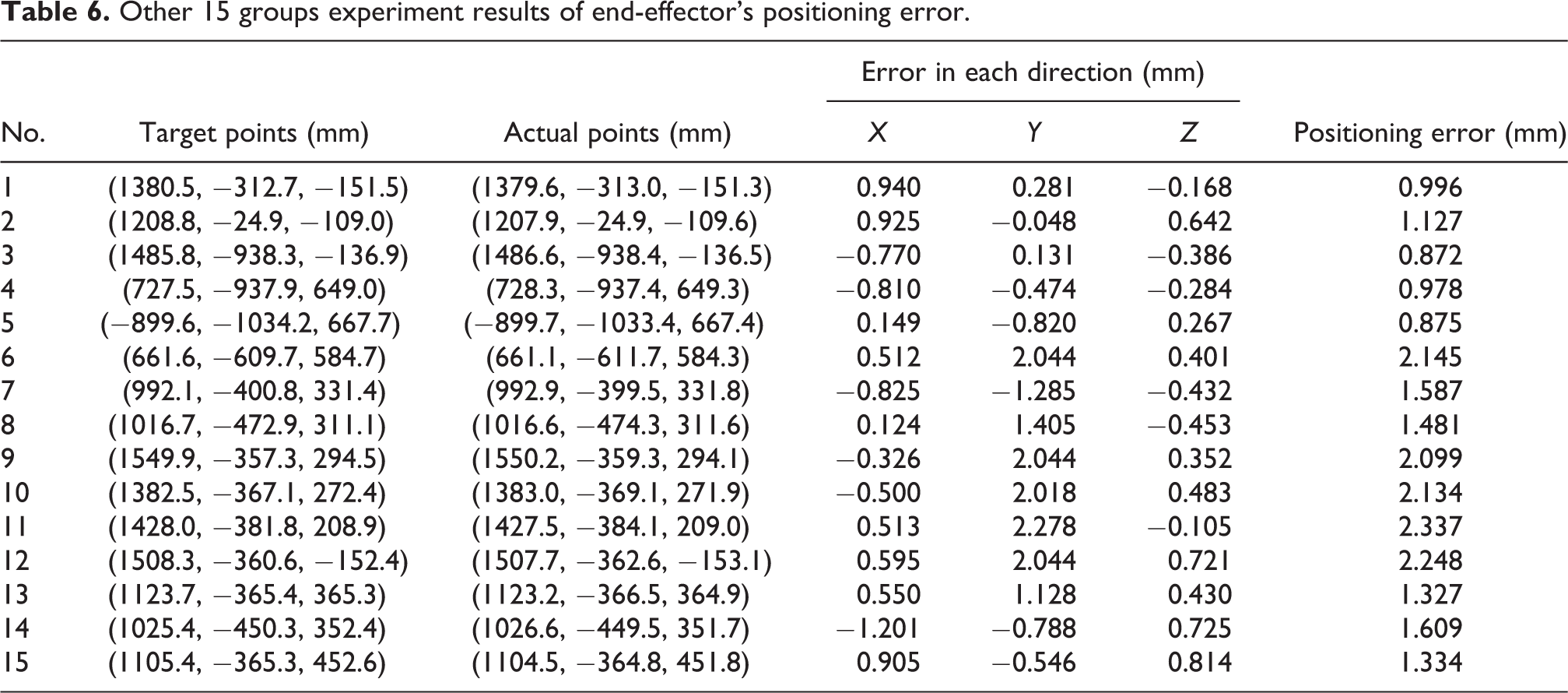
From Table 6, the maximum end-effector’s positioning error (equivalent to the positioning accuracy of end-effector) of ULAM is 2.337 mm, satisfying the technical index (4) (less than ±5.0 mm). The 2.337-mm equivalent to the maximum joint angle error of manipulator is 0.056° (arctan (2.337/2380 mm) = 0.056° and arm span 2.38 m). Compared with the study by Hildebrandt et al., 39 the maximum angle standard deviation of elbow joint of Orion 7P hydraulic manipulator (made by Schilling Robotics located in Davis, CA, USA) is 0.136°. The experimental results show that the ULAM has a better joint angle accuracy, which means the better positioning accuracy of end-effector.
Analyze the main error sources for the above experiment. (1) Practically, there exists clearance of joints; and (2) the designed manipulator is very long, and the area of the cross section of the manipulator is relatively small, which would cause deformation in the manipulator. All of these would affect the positioning accuracy of the end-effector. In addition, different control algorithms would also have some influences on the accuracy.
Trajectory tracking experiment of the end-effector when AUV is in dynamical positioning condition
In the pool environment, and under AUV’s dynamical positioning condition, the trajectory tracking experiment of the manipulator is conducted, to verify the positioning accuracy of the end-effector in trajectory tracking, which can satisfy the technical index 5 (less than ±100 mm).
The experimental procedures and measuring device are given as follows. AUV is in dynamical positioning condition based on control algorithm. Based on the given desired trajectory for the end-effector, the desired curve (desired angle-time response curve) of each joint is calculated by motion planning. According to the desired curve, each joint is rotated based on control action. And the real trajectory of the end-effector is measured. Evaluating the deviation between the desired trajectory and the real one, then the positioning accuracy of the end-effector is obtained.
The measurement scheme about the end-effector trajectory is shown in Figure 21.

Schematic diagram of the end-effector trajectory measurement.
In Figure 21, three contact displacement sensors (HLS-M, [Taiwan, China] linear accuracy 0.01%) are fixed in the measuring device and the distances between any two sensors are a, b, and c, respectively. In the process of experiment, the distance between the measuring end of the sensor and the end-effector of the manipulator can be measured in real time, denoted as L1, L2, and L3, respectively. Set the coordinate of the end-effector A as (xa, ya, za). According to the kinematic relation, the following can be derived

Based on equation (2), yielding to

The initial position of the end-effector is (850, −700, −300) mm. The experiment results are shown in Figure 22.

The end-effector trajectory tracking curve. (a) Trajectory tracking curve and (b) manipulator joint angle tracking. (1: target trajectory; 2: tracking curve; 3: target angle-time response curve; 4: cervical joint; 5: shoulder joint; 6: elbow joint; 7: wrist joint.)
Relevant data collected from Figure 22 are shown in Table 7.
The “sine curve” trajectory tracking error.

MTE: maximum tracking error.
In Table 7, the MTE (the evaluation indexes of end-effector trajectory tracking accuracy) in X, Y, Z direction is 23.53, 21.79, and 18.01 mm. The MTE and the mean tracking error are 36.78 and 13.01 mm, respectively, satisfying the technical index (5) (less than ±100 mm). In this article, the MTE (36.78 mm) accounts for 1.545% of the arm span (2.38 m). However, in the study by Zhang, 40 it also conducted the tracking experiment of the end-effector when AUV was in dynamical positioning condition, the MTE is within the range of (−15, 15) mm, which accounts for 2.0% of the arm span (the length of the underwater manipulator is about 0.75 m). According to the comparison, the results show that the developed underwater manipulator in this article has a high end-effector trajectory tracking accuracy, and it would be beneficial to improve the underwater coordination operation performance of underwater vehicle manipulator system (UVMS).
From Tables 6 and 7, the tracking error in tracking experiment (AUV is in dynamical positioning condition) is large than that in positioning experiment (AUV is fixed). First of all, in AUV positioning, the error in AUV position will have a great effect on the positioning accuracy of the end-effector. In addition, when the manipulator moves, the centers of the gravity and the buoyancy will be changed. This change will also bring negative impact on the AUV attitude control, especially in pitch and roll angles. Thus, when AUV is also dynamic positioning, the tracking error of the end-effector is worse than that result in “Experiment for the positioning accuracy of the end-effector when AUV is fixed” section.
Conclusions
This article investigated underwater long-arm hydraulic manipulator and its small-flow hydraulic driving device. Pool experiments were performed on the developed manipulator. A joint driving mechanism with “LHC + three-bar linkage + four-bar linkage” was developed. The experiment of single joint verified the effectiveness of the developed driving mechanism. A small-flow hydraulic driving device with “closed-loop” feature was developed and the experiment results show that a better control accuracy is obtained based on the developed device. Water is selected as a medium in the manipulator. A scheme with circulation in the “closed loop” and the improved sealing structure consisting of O-ring and Glyde-ring are developed. It avoids internal leakage to some extent. And experiment results show that a small amount of leakage has little impact on the end-effector’s positioning accuracy. The “vacuum + pre-pressurization” treatment was adopted for water in this article. It greatly reduced tracking error and motion hysteresis caused by the compressibility of water. Experiment results show that the MTE, RMSE, and MHT were reduced by 61.11%, 65.68%, and 60.49%, respectively, compared with the case under the untreated condition. The results verified the effectiveness of the “vacuum + pre-pressurization” treatment. Based on the UVMS experimental platform, both the end-effector’s positioning accuracy experiment and trajectory tracking experiment were conducted. And the experiment results show when the manipulator’s basis is fixed, the positioning accuracy of the end-effector is 2.337 mm, within the range of the technical index. However, when AUV is in dynamic positioning, the MTE and the mean tracking error of the end-effector in the “sine curve” trajectory tracking process are 36.78 and 13.01 mm, respectively.
Footnotes
Declaration of conflicting interests
The author(s) declared no potential conflict of interest with respect to the research, authorship, and/or publication of this article.
Funding
The author(s) disclosed receipt of the following financial support for the research, authorship, and/or publication of this article: This work was supported by the Basic Research Program of Ministry of Industry and Information Technology of People’s Republic of China (B2420133003) and the Fundamental Research Funds for the Central Universities of People’s Republic of China (HEUCF160701).