
Abstract
A new hydraulic chassis of rice transplanter is designed based on the paddy machinery operation requirements. Driving system adopts single pump four-motor scheme, and the anti-slide valve group is used to prevent the slippage of the shunt-wound hydraulic motors. Hydraulic steering system adopts single-way stable diverter valve for ensuring its response in time. Then, hydraulic system and components parameters are designed and calculated. The driving resistance and average slip rate are measured in paddy field. The experimental data verifies the correctness of theoretical calculation. The designed hydraulic driving system and steering system are simulated in AMESim. The simulated data, including pressure, flow, and torque, basically conform to the design requirement. The results verify the feasibility and reliability of chassis hydraulic scheme. The proposed design scheme may be extended to other vehicles for improving chassis performance.
Keywords
Introduction
In 2015, the rice planting area in China is about 30 million hectares, which accounts for 30% of China’s grain crop area and 20% of the world’s rice planting area.1,2 Nearly 200 billion kilograms of rice is produced every year. Therefore, rice production has an irreplaceable position in China.
Along with agricultural mechanization techniques, several dozen years development, rice tillage, harvesting, and processing have reached to a high level in China. However, only the rice planting mechanization has been struggling. In 2014, the rice plantation mechanization rate in middle and lower reaches of Yangtze River area which is more developed in China reached to 51.57%, but this rate in southwest region is only 20.23%. 3 Therefore, the design and generalization of high-speed rice transplanters is one of the most basic material guarantees to improve land productivity and resource utilization.
Rice transplanters work in the paddy field which has complex mechanical characteristics and deep mud feet. At the same time, its working quality also must be ensured.4–6 These unfavorable factors make sure that the higher requirements of chassis design are put forward.
The Professor Song Zhenghe of the Agricultural University of China studied expert system of chassis rapid design for high-speed transplanter in 2012. 7 Professor Shao Lushou of Anhui Agricultural University studied the transplanter adapting to deep mud feet paddy field in 2014. 8 Professor Zhang Wenyi conducted the measurement and analysis of steering radius of high-speed rice transplanter on different grounds. 9 But almost the research of rice transplanters is traditional machinery chassis which can basically meet the requirements of paddy field work. But it also has the following disadvantages: (1) complex and bulky transmission system and fixed and single arrangement, (2) unable to realize change speed continuously, (3) big turning radius, and (4) different to realize automation and intelligence control. In a word, traditional chassis cannot meet the development requirements of new agricultural machinery. In order to overcome the above shortcomings and meet the market demands, a new hydraulic chassis of high-speed transplanters is designed in this article. Compared to the existing traditional chassis, the new hydraulic chassis has the following advantages: (1) change speed continuously and increase speed variation range; (2) enlarged ground clearance and improved rice transplanters traffic ability; (3) more flexible layout; (4) lighter mass, higher power density, and better fuel economy; (5) the biggest steering angle reaches above 70°, so the rice transplanters can turn round easily in narrow area; and (6) hydraulic chassis provides a platform for automation and intellectualization.
In this article, a new hydraulic chassis driving system of high-speed transplanters is designed and hydraulic component parameters are calculated. Based on the paddy machinery operation requirements, chassis driving system adopts single-pump four motors and the anti-slide valve group is used to prevent the slippage of the shunt-wound hydraulic motors. Seedling motor and walking motors are series-wound for ensuring planting distance consistent. Hydraulic steering system adopts single-way stable diverter valve for ensuring its reliability and response in time and the hydraulic system provides power port for other working equipment. The running resistance and average slip rate are measured in paddy field and the experimental data verifies the correctness of theoretical calculation. Then, most main hydraulic component parameters are calculated based on experiment data. The hydraulic driving system and steering system are simulated in AMESim and the simulated results verify the feasibility and reliability of chassis hydraulic scheme. The results suggest that the proposed hydraulic chassis design scheme is effective and feasible for other agricultural machine chassis design.
Hydraulic chassis scheme design of rice transplanter
The hydraulic system design is a process that constitutes a new energy delivery system for completing one or more specific tasks. In consideration of machine usage, structure layout, working condition, load characteristic, and so on, the hydraulic system scheme is formulated. Then, the hydraulic components can be selected based on its displacement, pressure, and other parameters. For complex hydraulic system, the scheme can be confirmed after computer simulation analysis and modification repeatedly.
Rice transplanters work in the paddy field all the time which has complex mechanical characteristics. 10 In order to guarantee its working quality and performance, the general design requirements of hydraulic chassis of rice transplanter are as follows: (1) go forward and backward, (2) hydraulic braking system, (3) change speed continuously, (4) driven by four wheels and increase ground clearance, (5) adopt hydraulic steering mechanism and reduce turning radius, and (6) provide a platform for automation and intellectualization.
In order to meet the above requirements and ensure its working performance, chassis hydraulic system scheme is shown in Figure 1. Power delivery roadmap is shown in Figure 2.
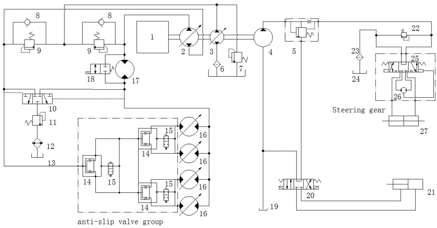
Hydraulic system scheme.

The roadmap of power delivery.
Chassis hydraulic system is composed of driving system, transplanting system, steering system, and other working equipment. In addition, supplement oil circuit and cooling circuit are taken as auxiliary system in the hydraulic scheme. It can be seen from Figure 1. Engine provides power to three hydraulic pumps. The variable displacement piston pump which is power output for driving system and transplanting system is main pump. It can control rice transplanter go forward and backward through changing displacement and rotation direction. Four driving motors are second-step variable displacement motors which are suitable for two operation models. The two kinds of operation models are, respectively, low-speed walking with high load and high-speed walking with low load. High-speed low-load working model is walking on the road without transplanting operations and its maximum speed is 2.5 m/s. Low-speed high-load working model is walking on the paddy field with transplanting operations and its maximum speed is 1.5 m/s. This hydraulic system can change walking speed and amplify speed variation range by input or output adjustment. The working of the transplanting equipment is controlled by the bypass valve.
Four driving motors are shunt-wound. This scheme has a drawback that the hydraulic system can only maintain the pressure requirement of the minimum load wheel motor when a wheel appears skid because of bad adhesion conditions. Then, the adhesion force of rice transplanter is too little to move. In order to solve this problem, the designed hydraulic system uses anti-slip valve group which is composed of three anti-slip valves. Each anti-slip valve includes a split flow valve and a bypass valve. These split flow valves will divide hydraulic oil in half when any one wheel appears skid.11,12 In this way, every driving motor will gain equal flow, so the skid problem can be solved. Bypass valves which play an important part of controlling speed differential are connected when none of the motors appear skid. Transplanting motor and four driving motors formed a series-wound circuit. The former’s oil flow is equal to the sum of four driving motors. There is a rotation encoder connected to the wheel axle which is used for measuring the walking speed. Another rotation encoder is used to measure the engine rotation. The total flow of hydraulic system is the product of rotation speed of the engine and displacement of the piston pump. The transplanting frequency depends on the flow through the transplanting motor whose displacement is constant. So the required flow of the transplanting motor at different walking speeds can be known. The total flow of hydraulic system is always surplus. The excess flow will flow away through bypass valve which is proportional valve. The flow through the bypass valve can be controlled by the opening of the valve core. In this way, it can guarantee the relationship between the walking speed and transplanting frequency. Therefore, transplanting distance is consistent absolutely.
Gear pump which provides power to steering system and other equipment is a constant displacement pump. The output of gear pump connects a single-way stable diverter valve and this valve ensures the steering flow is stable preferentially. Steering gear is the key section which adopts open core and no responding system. It is composed of steering valve and metering motor. When the steering wheel is rotated, the core and sleeve of turning valve begin to move relatively. Hydraulic oil goes through metering motor and steering hydraulic cylinder successively. And at the same time, the metering motor also drives valve sleeve rotation. The opening of turning valve is reduced until shut down totally and then the steering system reaches a new equilibrium. 13 Steering actuator uses a double piston cylinder which can ensure steering force and displacement is equal for two directions. The other circuit of the single-way stable diverter valve is connected to controlling component and actuator of other equipment.
Chassis hydraulic system needs to adjust flow and change flow direction at any time during working process. The system should have good speed rigidity and responding speed; therefore, a closed hydraulic circuit is adopted. In the closed circuit, main pump that is input component does not absorb oil form fuel tank directly, but it is connected to the driving motors head to tail. The closed circuit can meet the requirements of rice transplanter chassis well, but its thermal diffusivity and leakproofness are bad. To solve above problems, oil supplement and cooling circuit are introduced. The cooling circuits exhaust hot oil which will be recycled after cooling back to tank. The oil of hydraulic system will be reduced due to cooling circuit discharge hot oil and components leakage. Oil supplement pump supple oil to low pressure side through check valve and its displacement is about 15%–25% of main pump.14–16 Oil supplement pressure limited valve is used to maintain a basic pressure of this closed circuit. In addition, closed hydraulic circuit is a symmetrical and reversible system. It can not only output positive torque to drive transplanter but also absorb negative torque to realize braking function. The braking mechanism can replace traditional friction components.
Driving resistance calculation and measuring experiment
Driving resistance calculation
The normal driving conditions of rice transplanter should satisfy the conditions as shown in formula (1) 12

where F is traction, Ff denotes rolling resistance, Fw denotes air resistance, Fg denotes grade resistance, and Fa denotes acceleration resistance.
Rolling resistance is equal to the product of normal support force from ground and rolling resistance coefficient. Grade resistance is equal to the product of total mass and gradient. Air resistance is influenced by positive windward area, body shape, and body material, and its value is proportional to speed square. Generally, air resistance can be neglected when the vehicle maximum speed is less than 50 km/h. 17 For rice transplanter, its maximum walking speed is 9 km/h, so its air resistance can be neglected in calculation process. Acceleration resistance is a kind of integrated inertial resistance because of acceleration variation. Generally, for low-speed vehicles, the acceleration resistance is small. It can be calculated by formula (2) approximately 12

where Fa is acceleration resistance, m denotes total mass, g denotes gravitational acceleration, and λ denotes acceleration factor. λ is equal to the specific value of actual acceleration and gravitational acceleration.
Rolling resistance coefficient and maximum adhesion coefficient for rubber tires of rice transplanter at different roads are shown in Table 1.
Rolling resistance coefficient and maximum adhesion coefficient for rubber tires at different roads.

The total mass of designed rice transplanter with full load is about 1200 kg and its gravity is 11,760 N. Rolling resistance coefficient in paddy field chooses maximum value 0.25. Gradient is 13% which is corresponding to slope angle 8°. By calculation, acceleration factor is 0.035 m/s2. The above parameter values are taken into formula (1). The calculation results show that the maximum driving resistance is 4880 N when the rice transplanter is walking on the paddy field. And it is obvious that when walking on other types of roads, the transplanter’s rolling resistance coefficient is less. Therefore, 4880 N is the maximum driving resistance in any working condition.
Driving resistance measurement experiment
Paddy machinery is different from the road machinery because the former working in the paddy field has complicated mechanical properties. Therefore, theoretical calculation of the driving resistance might result in larger error. In order to verify the correctness of calculated results, the driving resistance measurement experiment in paddy field is conducted. Two existing same rice transplanters (its mass is about 1340 kg with full load) are arranged in the paddy field and the ground gradient is zero. In the experimental process, a rice transplanter pulls another one and a tension sensor is settled between them. The maximum driving resistance can be measured by the tension sensor. Because now there is no paddy field driving resistance measurement standard, the experiment conditions are settled (refer to GB/T 12534). 18 According to the standard GB/T 12534 called “general principles of road resistance measurement method,” the measurement procedures are conducted as follows:
Mud feet depth and length of paddy field are about 20 cm and100 m, respectively;
Tire inflation pressure conforms to the standard;
Walking speed is 0.8 m/s;
Tension sensor range is 20,000 N.
The experimental photograph is shown in Figure 3 and the experimental data are shown in Table 2.

Experiment of driving resistance measurement in paddy field: (a) experiment site and (b) tension sensor.
Driving resistance data comparison.

It can be seen from Table 2 that the measured driving resistance is slightly less than theoretical calculated data. But the error is little and the relative error is only 2.73%. The results prove that the calculated driving resistance is basically right.
Chassis hydraulic system design
Slip ratio measurement experiment
In order to calculate hydraulic system flow, the average slip ratio of rice transplanter in paddy field needs to be measured. Paddy soil has rheologic property so the slipping ratio of the machines working in the paddy field is difficult to use empirical formula to estimate. To get accurate average slip ratio, the slip ratio measurement experiment is conducted.
The slip ratio calculation formula is shown in formula (3) 19

where δ is slip ratio, st denotes theoretical walking distance, and ss denotes actual walking distance.
Before experiment, the theoretical walking distance of rear wheel rotation 10 laps is calculated, and then the actual walking distance is measured by meter ruler. Rear wheel rotation laps are measured using revolution counter. The experimental photograph is shown in Figure 4, and the comparison between experimental data and theoretical data is shown in Table 3.

Slip rate experiment in paddy field: (a) walking straightly and (b) distance measurement.
Slip rate data comparison.

It can be seen from Table 3 that the maximum slip ratio is 4.54% and the minimum slip ratio is 2.58%. The value of measurement average slip ratio is 3.37%. Paddy wheels of rice transplanter reduce slip ratio effectively.
Calculation of hydraulic driving system parameters
A characteristic of static hydraulic driving device is that it has good adaptability for multiple output methods. As long as all driving wheels have enough adhesion and the allowable pressure of all components is higher than maximum system pressure, driving motors can be connected in parallel. No matter if all wheel radius and motors specification are same, the hydraulic system can operate in phase.
The displacement of one or one group motors connected in parallel can be calculated by formula (4) 12

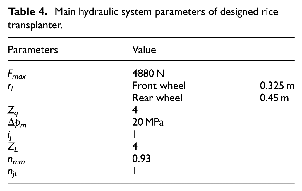
where Fmax is maximum driving resistance, rl denotes wheel dynamic radius, Zq denotes wheel number for each driving motor, Δpm denotes hydraulic system pressure, ij denotes transmission ratio between motor and wheel, ZL denotes the driving wheel number, nmm denotes motor mechanical efficiency, and njt denotes mechanical transmission efficiency.20,21
The designed parameters are shown in Table 4. After calculation, the displacement of front wheel and rear wheel motors are 138.2 and 191.3 mL/r, respectively.
Main hydraulic system parameters of designed rice transplanter.
The total flow of driving system hydraulic circuit can be calculated by formula (5) 12
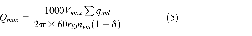
where Qmax is total flow, Vmax denotes maximum walking speed of rice transplanter, its value is 2.5 m/s, qmd denotes motor equivalent displacement, rl0 denotes wheel dynamic radius of reference wheel, nvm denotes system volume efficiency, its value is 0.88, δ denotes slip ratio, and its value which is gained by measurement experiment is 3.37%.
The four wheels’ radius of designed rice transplanter is different. The equivalent displacement of each motor can be calculated by formula (6) 15
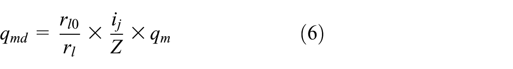
where qmd is motor equivalent displacement, rl0 denotes wheel dynamic radius of reference wheel, its value which is equal to front wheel radius is 0.325 m, rl denotes calculated wheel dynamic radius, ij denotes transmission ratio between motor and wheel, Z denotes wheel number for each driving motor, and qm denotes motor actual displacement. After calculation, motor equivalent displacement is 138.2 mL/r.
The total flow of driving system hydraulic circuit can be calculated by combining formulas (5) and (6). Its value is 13.26 L/min.
The maximum displacement of main pump can be calculated by formula (7) 12

where qpmax is maximum displacement of main pump; Qmax denotes maximum flow; npmax denotes highest rotation speed of engine, its value is 2000 r/min; and nvp denotes motor volume efficiency, its value is 0.97.
Calculation of hydraulic steering system
The biggest steering torque of rice transplanter can be calculated by formula (8) 22

where T is biggest steering torque, Z denotes vertical load of steering wheel, and its value is 5880 N approximately.
The required thrust force of hydraulic cylinder can be calculated by formula (9) 20
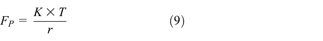
where FP is required thrust force, K denotes coefficient, and its value is 1.5. T denotes biggest steering torque, r denotes minimum arm of force, and its value is 0.l. After calculation, the biggest required thrust force is 1960 N.
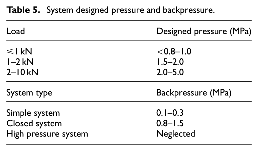
According to Tables 5 and 6,21,23 main parameters of steering system are selected. The designed pressure and backpressure are 2.0 and 0.2 MPa, respectively. Rod diameter ratio is 0.5.
System designed pressure and backpressure.
Rod diameter ratio selected by procurement.

The hydraulic cylinder piston diameter can be calculated by formula (10) 24

where D is piston diameter and Fp denotes required thrust force. ncm denotes hydraulic cylinder efficiency and its value is 0.95. p1 denotes main working chamber pressure and its value is 2.0 MPa. p2 denotes backpressure and its value is 0.2 MPa. After calculation, the piston diameter and rod diameter are, respectively, 38 and 19 mm.
Simulation and analysis
Simulation and analysis of hydraulic driving system
The hydraulic system of chassis is complicated, so computer simulation is adopted to verify its reliability. The designed hydraulic driving system model is established in AMESim software. The established model of hydraulic driving system is shown in Figure 5. Part settled parameters of each component are shown in Table 7.

The established model of hydraulic driving system in AMESim software.
Each component settled parameters of driving system.

In AMESim, parameters are settled according to Table 7. The designed hydraulic driving system is simulated. Simulation time is 2 s and calculation step is 0.01.
It can be seen from Figure 6 that in 0–0.3 s, the pressure fluctuation is intense. At initial period, the system pressure is higher than settled safety pressure 20 MPa, but this pressure value is less than allowable pressure of each component. The system pressure is limited to 20 MPa by the safety valve. After 0.5 s, motor pressures tend to be stable. The pressures reach a stable value at 17.27 MPa. The simulation results meet the design requirements.

Pressure variation curves of motors.
It can be seen from Figure 7 that the torque of front and rear motors are shown in dotted line and solid line, respectively. In 0–0.3 s, the torque fluctuations of front and rear wheel motors are intense. The maximum torque of front and rear wheel motors are, respectively, 549.89 and 761.30 N m. After 0.4 s, two torque variation curves tend to be stable. The final torque value of front and rear wheel motors are, respectively, 379.44 and 535.23 N m. The torque value meets the driving power requirement of rice transplanter.

Torque variation curve comparison between front and rear wheel motors.
It can be seen from Figure 8 the flow of oil supplement pump and flushing shuttle valve are shown in solid line and dotted line, respectively. The flow of oil supplement pump is 2.0 L/min consistently because it is a constant displacement pump. The flow variation of flushing shuttle valve has fluctuated greatly in 0.5 s. After 1.0 s, its flow reaches a stable value at 2.01 L/min. Oil supplement flow accounts for about 15.1% of the primary system flow. The simulation results meet the design requirements.

Flow variation curves of oil supplement pump and flushing shuttle valve.
Simulation and analysis of hydraulic steering system
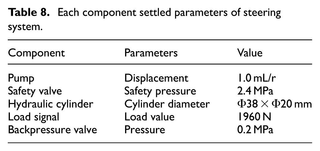
In AMESim, steering gear can be equated to a series of three-position four-way direction control valve and variable throttle valve. When turning the steering wheel, a control signal is given to make the core of direction control valve to move. In this way, connected and disconnected models of hydraulic circuit are simulated. In addition, a ramp signal is used to control the opening of throttle valve and it can ensure that the flow through the throttle valve is proportional to the steering wheel angle.23–26 The established model of hydraulic steering system is shown in Figure 9. Part settled parameters of each component are shown in Table 8.

The established model of hydraulic steering system in AMESim software.
Each component settled parameters of steering system.
In AMESim, parameters of steering system are settled according to Table 8. The designed hydraulic steering system is simulated. Simulation time is 5 s and calculation step is 0.01. The control signal of throttle opening is shown in Figure 10. The flow curves of throttle output and hydraulic cylinder rodless chamber are shown in Figure 11.

The control signal of throttle opening.
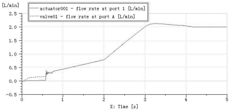
The flow curves of throttle output and hydraulic cylinder rodless chamber.
It can be seen from Figure 10 that the control signal of throttle opening is a ramp signal. In 0–2.0 s, the signal value changes from 0.025 to 0.125 which is equivalent to the throttle valve opening from 0% to 25% of maximum opening. In 2.0–4.0 s, the signal value changes from 0.125 to 0.50 which is equivalent to the throttle valve opening from 25% to 100% of maximum opening. After 4.0 s, the signal value is kept at 0.50.
The flow curves of throttle output and hydraulic cylinder rodless chamber are shown as dotted line and solid line, respectively, in Figure 11. In different time stage, the output flow is different when the controlling signal is changing. The flow changing trend of the variable throttle valve and cylinder output are basically identical. The steering gear model shows that the flow of hydraulic cylinder is proportional to the steering wheel angle. This result proves that the established steering gear in AMESim is basically right.
The working pressure curve of hydraulic cylinder is shown in Figure 12. The pressure of the hydraulic cylinder has risen sharply in 0–0.7 s. After 1.0 s, its pressure tends to be stable. Finally, the pressure is kept at 2.01 MPa which is identical to designed pressure basically.

The working pressure curve of hydraulic cylinder.
Conclusion
In this article, the design, experiment, hydraulic component parameters calculation, and simulation of hydraulic chassis of rice transplanter are conducted. Based on the paddy machinery operation requirements, chassis driving system adopts single-pump four-motor scheme and the anti-slide valve group is used to prevent the slippage of the parallel hydraulic motors. The oil supplement circuit and cooling circuit are settled for ensuring its stability and reliability. Hydraulic steering system adopts single-way stable diverter valve for ensuring its response in time and the hydraulic system also provides power port for other working equipment. Then, hydraulic system and component parameters are designed and calculated. The driving resistance and average slip rate are measured in paddy field and the experimental data verifies the correctness of theoretical calculation. The experimental results show that the average error of driving resistance is 2.73% between experimental results and theoretical calculation. The slip ratio is 3.37%. And then the designed hydraulic driving system and steering system are simulated in AMESim software. The simulated data, including pressure, flow, and torque, basically conform to the design requirement. The results verify the feasibility and reliability of chassis hydraulic scheme. The proposed design scheme of hydraulic chassis may be extended to other types of agricultural machine and thus is beneficial for hydraulic system design in engineering.
Footnotes
Handling Editor: Jose Ramon Serrano
Declaration of conflicting interests
The author(s) declared no potential conflicts of interest with respect to the research, authorship, and/or publication of this article.
Funding
The author(s) disclosed receipt of the following financial support for the research, authorship, and/or publication of this article: This work has been supported by the Major Reserve Program of Chinese Academy of Agricultural Sciences (Grant no. Y2017XM05) and partly supported by the National Research and Development Plan (Grant no. 2017YFD0700704).