
Abstract
In the domain of modular self-reconfigurable robotic systems, self-reconfiguration is known to be a highly challenging task. This article presents a novel algorithm for distributed self-reconfiguration by combining cellular automata and L-systems. Cellular automata is used to handle the relative motion planning of decentralized modules. L-systems are introduced to provide a topological description for the target configuration. The turtle interpretation is extended to modular robotics to generate local predictions for distributed modules from global description. Local predictions spread out in the system through gradient propagation. Modules, using cellular automata rules managing local motion, climb gradient to the expanding fronts for constructing global configurations. Both simulations and experiments have demonstrated the practical effectiveness of the proposed algorithm.
Keywords
Introduction
Modular self-reconfigurable (MSR) robotics are built from completely independent working robotic modules. The self-reconfiguration or translation of MSR robots is to rearrange the positions and connection ways of inner modules. This is different from the reconfiguration by regulating the passive joints to the associated Denavit–Hartenberg parameters. 1 Stoy et al. 2 explained self-reconfiguration problem as: “Given an initial configuration and a goal configuration, find a sequence of module moves that will reconfigure the robot from the initial configuration to the goal configuration.” The self-reconfiguration process intimately couples hardware and control methods.
Fukuda and Nakagawa 3 gave the basic scenario that motivates self-reconfigurable robots. Since then there have been various robotic hardwares including SuperBot, 4 ATRON, 5 CKBot, 6 M-TRAN, 7 M-Cubes, 8 Replicator-Symbrion, 9 Sambot, 10 Cross-Ball, 11 SMORES 12 Roombots, 13 and M-block. 14 Based on the UBot 15,16 robots, we design a new modular mobile robot, which has the properties of MSR robots and mobile robots. This article will focus on the distributed self-reconfiguration of this new robot.
Choosing the appropriate mechanism for controlling self-reconfiguration is difficult, due to the diversity and various scales of available motion strategies. Many control algorithms have been developed to achieve the adjustment of global configuration. The centralized control has been proven to be an NP problem, 17 and the decentralized research has attached the most focus. There are a few absolutely decentralized algorithms without either external controller or predefined configurations. 18 –22 The configuration emerges through interaction of independent modules with surroundings or tasks at hand. Although the robustness of the method has a high match with the distributed nature of modular robots, the process can hardly converge to effective configurations. In some cases, it is the configuration that is of great concern.
To guarantee convergence to predefined structures, a global-centralized to local-distributed model is widely used. That is, an external controller takes a high-level centralized translation of target configurations to executable rules for independent modules. The rest self-reconfiguration depends on the automatic interaction of decentralized modules. Stoy et al. 23,24 take an overlapping bricks approach to convert the goal configurations into lattice automata rules. Rubenstein and Shen 25 develop an approach that conveys a complete description of the desired configuration to each module in the system. More similar research work can be found in papers. 26 –30
While allowing large collections of independent modules to form determinate shapes, the functionality is limited to simulation environments by attached assumptions. The problem of unpractical assumptions has little attention in the self-reconfiguration community may be because it is not apparent in simulation studies. But it has been a corner stone of self-reconfiguration control for physical robots. For example, the frequent adjustment of inner rules or “the strategy for local position in geometric representation” 24 cannot be achieved by physical modules working in real words, because the geometric representation can only be achieved in simulation.
MSR robots are dynamic systems with changing topology and geometry. The problem of distributed self-reconfiguration is a computing paradigm with a close coupling of topology, geometry, and computation. Inspired by the growth of cell complexes in nature, we introduce L-systems for defining the development of robotic structures. The turtle interpretation is extended to lattice robotics for providing modular-level information about global sense of the target configuration, which is a fundamental problem in distributed self-reconfiguration. 31 The sequential movement of turtles makes a practice algorithm for physical robots.
Although robotic modules cannot generate new modules at neighboring lattice as division of living cells, they can move on the surface of other modules. This cluster-flow locomotion achieves the development of structures by continuously moving new modules to the front of growing limb. Cellular automata (CA) 32 is taken to handle the local movement of distributed modules.
A simplified set of CA rules is designed and verified in both simulations and experiments. This simplification in numbers is a great forward relative to previous work on CA for modular robots. A fundamental problem about previous work on implementation of CA is that as the task and configurations become more varied, the rule sets become more complex. In fact, for a simple cluster-flow locomotion, 927 rules were needed. 33
The major differences between our approach and those of other researchers are summarized below. The simplified CA rules are a great forward to previous work by reducing rule numbers. L-systems and turtle interpretation are introduced to provide local predictions for distributed modules. The proposed algorithm is practical for physical robots.
The remainder of this article is organized as follows. In section “Distributed locomotion based on CA,” we explain the algorithm formulation in detail. Section “Lindenmayer systems and turtle interpretation” demonstrates the extension of L-systems in self-reconfiguration. Simulations are described in section “Self-reconfiguration process” to verify the functionality of proposed method in simulations. Experiments on physical robots are shown in section “Experiments.” Section “Results and discussion” offers a brief discussion of experimented results.
Distributed locomotion based on CA
To handle the geometric constrains, limited local information, and limited computing ability, the CA is used for managing the local coordination of decentralized modules. A simplified set of CA rules is designed for cluster-flow locomotion of modules.
The reconfigurable mobile robot
The MSR Mobile (Seremo) robot is designed as a lattice MSR robot and mobile robot. As shown in Figure 1, each module is a complete robot by itself with onboard sensors, actuators, processor, battery, and means of communication.

The 2-D reconfigurable mobile module. 2-D: two-dimensional.
Sensors, a limit switch on each four connecting face, are limited to directly neighboring objects, including obstacles and modules.
Actuators include a servo and a direct current (DC) motor to control the mobile motion. The servo bring wheel to the pivoting axis direction, after which the DC motor will handle pivot in needed orientation. A module can pivoting relative to another module along one of the four edges and couple of modules can mobile as multiple wheeled robots.
The processor is modularly designed for quantity production and maintenance.
Onboard battery allows modules to work 2 h at least.
Communication is based on inner infrared on all four connecting faces. The module will only try to exchange information with neighbors on the direction with limit switch down.
Compared with other MSR roboticmodules with wheels, 12,34,35 this module achieves all motion of sliding cube model (SCM) in two dimensions by pivoting and robots can move as a wheel system. As shown in Figure 2, a single module contains one servo, a DC motor, and a wheel. The wheel is connected to the output shaft of gear reducer of DC motor.

The pivoting motion of Seremo robotic modules.
The servo controls axial direction of wheel through a pinion unit system, including the internal gear, external gear, and transmission shaft. The pinion unit system is used to expand the slewing area of servo. The axial direction of wheel can reach any of the four edges. The center axis of robotic frame and transmission shaft is coincided, which makes the wheel decentered, as shown in Figure 2. When servo selecting and keeping the axial direction of wheel, the rotation by DC motor makes robotic frame pivoting around the selected edge.
This module takes passive connecting strategy using diametrically polarized magnets. Each frame holds eight diametrically polarized magnets in its four edges and four faces, as shown in Figure 1. Magnets in edges can quickly form magnetic, non-gendered hinges, which can provide rolling axis in pivoting motions. Another important function of magnets, especially these four magnets in faces, is solving the alignment problem when rotation finishes. These modules provide a simplified realization of modular actions in SCM 14 using pivoting. As shown in Figure 3, a seremo module is capable of convex and concave transition between different planes and linear motion on a plane.

The basic motion of designed modules and the simulated movement represented by squares.
Local motion planning by CA
An innovative method of independent motion planning of modules in parallel is achieved by CA, that is, the distributed self-motion planning of a group of Seremo modules to autonomously connect to and disconnect from each other through pivoting motion.
Achievable information of independent modules in decentralized systems is limited to neighboring positions through local communication. No global broadcast information is available. Modules in this article can get three kinds of information, as following: Module: With limit switch down and successful infrared communication. Obstacle: With limit switch down but no infrared communication. Free: With limit switch up.
The motion planning of mechanical modules is integratedly affected and influenced by many factors, including physical, geometry constrains, and limited local information. Synthesizing each constraint, a simple set of CA rules is designed with only two rules, as shown in Figure 4. Rule 1 describes the convex and concave transitions with two possible gradient directions in an either-or relationship, D 1 or D 2. Rule 2 describes the linear motion. This set of rules is simplified in rule numbers compared with existing work. 33,36

A set of CA rules for locomotion of Seremo robotic systems. Modules are represented by squares. CA: cellular automata.
The designed CA rules separate moving module (move in rules description) from current module (do the planning work in rules description). Traditionally, the moving module and current module are the same module that senses the gradient direction and takes movement. But the free state of target moving lattice of moving modules stops directly determining gradient direction. The moving module needs moving around. This separation lets the current module determines the gradient directly, which avoids random movement of modules. For details of how to implement CA for cluster-flow locomotion can refer to our previous work. 37,38
For the absence of centralized planning and synchronization, the global connection and deadlock are common problems in decentralized systems. To avoid disconnection of single or groups of modules, all neighboring modules of the moving module must find and maintain a connection path to the current module until the movement of moving modules. A random motion strategy is taken for the deadlock problem. A module will choose a random direction rather than the gradient direction after certain times of successive fails of motion planning. More implementing details about those two problems are given in our previous work. 38
To solve the collision problem of different modules moving to the same lattice position, moving modules will go back and abandon this motion plan if having any collision with other modules during movement. Then, the current module will take a random sleeping time before next motion planning, which avoids original motion plans at the same time in all those current modules.
Lindenmayer systems and turtle interpretation
Lindenmayer systems
An L-system 39,40 is a mathematical theory of multicellular development using a grammatical rewriting strategy, which parallelly applies rewriting rules (or productions) to a string of symbols. Rewriting has proven to be a useful technique for automatically constructing complex creatures 41 starting from a simple string or just one symbol. It has long been used to model the development of higher plants and complex branching structures. 42,43 This biological pattern is employed in MRS robotics to handle the macroscopic topology in distributed self-reconfiguration process.
Turtle interpretation
L-systems can only give a topological description of complex creatures in string of symbols. To get a three-dimensional (3-D) geometrical structure from a symbols description by L-systems, the well-known turtle interpretation 44 is considered. The basic idea of turtle interpretation is quite intuitive and can be found in many standard handbooks. 45,46 We only recall here some basics principles.
A turtle exists in N-dimensional space (usually
As an illustrative example, Figure 5 gives an interpretation on a simple L-system for a cross shape graph. This simple L-system contains only one reproduction rule. The interpretation of X has no graphical meaning and can only generate new symbols as reproduction rules description. Movement paths correspond to graphs described by L-systems.

Turtle interpretation of a simple L-system for a cross shape graph.
To get branching structures, the bracketed symbols, [ and ], are used to generate simultaneously developing substructures in distributed robotic systems. A new turtle turns up at the symbol [ and ends at the corresponding ], such as turtle 2 and turtle 3 in Figure 5. Symbols between [ and ] will be interpreted to an attached substructure. The current turtle will slide over symbols from [ to the corresponding ] and continue to interpret following symbols, for example, the interpretation by turtle 1 for X appended geometry in Figure 5. For the distributed nature of modular robots, multi-branching structures, each branch with an independent turtle, are allowed to develop in parallel. For example, the three turtles, turtle 1, turtle 2, and turtle 3, interpret simultaneously for X appended geometry in Figure 5.
Following those existed ideas,
44,47
turtle commands extended to 3-D lattice robotics contain two kinds of information: length (l) and scale (r), that is, V(l, r), where
The length parameter l is introduced to get structures with connected branches in different lengths, as defined in Figure 6. With turtle’s step size fixed at one lattice module, the length value l can be an integer about the number of modules connected in liner. The scale parameter r defines a radius for attaching modules around the branching limb, which leads to segments in various radius, for example, the crane in Figure 12. Along with development in length direction, the branch extends in radius by gradually attaching modules around the surface, which is similar to the growth of tree rings. This kind of extension avoids the hollow structure.

The length item l and scale item r in designed L-system symbols for 3-D lattice space. 3-D: three-dimensional.
All basic symbols used in our system for 3-D lattice configurations are listed in Table 1. The definition of directions is borrowed from work by Hanan. 45
L-system language for lattice-type MSR robotic configurations.

Turtles in MSR robots move through connected robotic modules. Connected modules on the sequence of turtle paths form reconfiguration results. During the turtle interpretation process, modules have three interpretation states:
Turtle module: The module in current walker position of turtles, called turtle module in this article, does a moving search work as the turtle.
Structure module: When all neighboring lattice stations meet the description requirements, the turtle module will change state to structure module, which is a fix part of the final configuration. Those modules attached by turtle module for segment radius.
Mobile module: The rest of modules in the system are mobile modules, which can move to needing positions for structure growth.
The coordinate system for L-system description maintains global state in different modules. Local communication between directly connected modules handles this refreshment. As shown in Figure 6, the turtle’s orientation in 3-D lattice space is represented with three vectors:

L-systems are theoretically applicable to MSR robotics, because the sequence of turtle language interpretation 44 has a match with the global connectivity of robotic configurations. Symbols in the alphabet V are used as a turtle’s moving commands for graphic interpreter, in the self-reconfiguration, these commands will be related to the movement and reconnection of the robotic modules.
Self-reconfiguration process
The gradient attraction 24,48 is used to combine global description by L-system and local motion by CA. Turtle modules attract mobile modules to the neighboring position on the turtle moving direction. New attached mobile modules change state to turtle modules and take over moving search work. Global reconfiguration develops in this growth pattern.
Modules with turtle module state act as a source and create a gradient in the system, which have the same function with seed modules. 24 In branching structures, more than one turtle modules are allowed to exist simultaneously, which create gradient independently without synchronization. All modules in the system take part in the translation of gradient through local communication between directly connected modules.
In decentralized robotic systems, gradient values in different modules are updated independently without synchronization with other modules. Directly connected modules exchange gradient values and then decentralized modules update inner value independently. Modules send out the gradient value of itself to connected modules and receive gradient from them. The maximum received value is decreased by one and sets to be the gradient value of the module itself.
As to the gradient direction, a module selects the direction pointing to a connected module having a greater gradient value than the value of the module itself. Specially, the turtle module has a gradient direction pointing to the turtle moving position. One module may have more than one gradient directions at the same time. Along each gradient direction successively, modules, as the current module in CA rules, take motion planning by CA rules, and let mobile modules climb the gradient.
Figure 7 gives an illustrate example in two-dimensional (2-D) about how gradient combines cluster-flow locomotion by CA and local prediction by interpreting L-system symbols. A turtle module searches whether a connected module is required in a neighboring lattice, which is the modular-level prediction for robotic reconfiguration. If the neighboring lattice has a connected module, this connected module will change state to turtle module and continue interpretation. On the contrary, if the lattice is free of modules, the turtle module will create a gradient by setting a certain gradient value for itself, for example, 20 in Figure 7. All modules in the system take motion planning by CA rules and transmit gradient. Mobile modules climb the gradient to gradient source (the turtle module). The turtle module, having a gradient direction on growing orientation, keeps taking motion planning by CA rules and checking if a module is connected in front of it. New attached mobile modules will change state to turtle modules and continue the moving search work. Self-reconfigurations rise in this development pattern by continuously attaching new modules at turtles’ moving direction.

With gradient attraction combining global description and local motion, mechanical robots reconfigure by continually attaching mobile modules at the turtle moving direction.
Simulations
The proposed algorithm is especially suitable for branching structures, which are so common in the word around us—in cellular system, in atomic system, and also in robotics. For configurations with obvious reproducing phenomena, the self-reconfiguration can start directly using manually designed rewriting rules, such as self-reconfigurations in Figures 8, 9, and 10.

Self-reconfiguration to a cross-shape structure from lattice configuration.
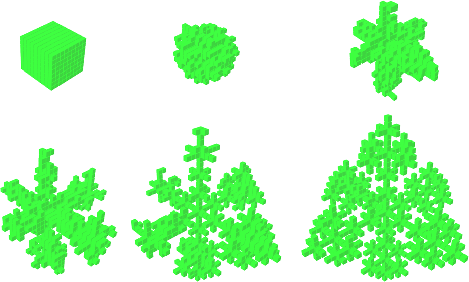
Self-reconfiguration to a snow-shape configuration in atomic system.

Self-reconfiguration to zigzag box-shape configuration in arts.
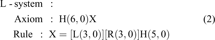
The first example takes the simple L-system in Figure 5. Different parameters are assigned, as shown in equation (2). Figure 8 shows the corresponding self-reconfiguration process of a sliding cube module (SCM) 14 robot 49
Although the designed CA rules in this article describe 2-D movement in a motion plane that holds gradient direction, they can be used to handle 3-D locomotion. One SCM has six connecting faces and neighboring faces are perpendicular to each other. Together with a gradient direction pointing to one connecting face, all the four neighboring perpendicular connecting faces can form a motion plane for movement in CA rules. The module will check the four faces successively until finding a successful motion plan according to CA rules. When a module has more than one gradient direction at the same moment, it will repeat the verification for every gradient direction.
Self-reconfiguration starts from the first turtle module, which receives the axiom of designed L-system. During the self-reconfiguration, new turtle modules receive both turtle state and L-system symbols from father turtle module. The coordinate system is also refreshed at the same time through local communication. When all neighboring lattice stations meet the description requirements, the former turtle module will change state to structure module as a default body part of final configuration. Structure modules will not move to other parts anymore.
Along with each translation of L-system symbols, the length item l of currently interpreting symbols is reduced by 1. The rest symbols are translated without any adjustment. One branch ends at the turtle module with length
For the decentralized nature of modular robots, more than one turtle modules can exist simultaneously and interpret symbols independent without synchronization. Turtle modules interpreting the predecessor X do the rewriting work and replace X with successor symbols. As shown in Figure 8, the rewriting work generates bracketed symbols
After the reproduction, two new turtle modules for subbranches rise from the bracketed symbol [ in both
For complex configurations without obvious reproduction characters, manually designed L-system codes can also be effective. Branching structures consist of connected segments. In Figure 11, a label is associated to each segment. When selecting segment a as the root segment (any segment can be the root), the branching structure can be described by a corresponding tree graph as shown in Figure 11. Each segment is a node in the tree graph. An edge connects two nodes x and y if and only if the segments x and y are joint in the branching structure.
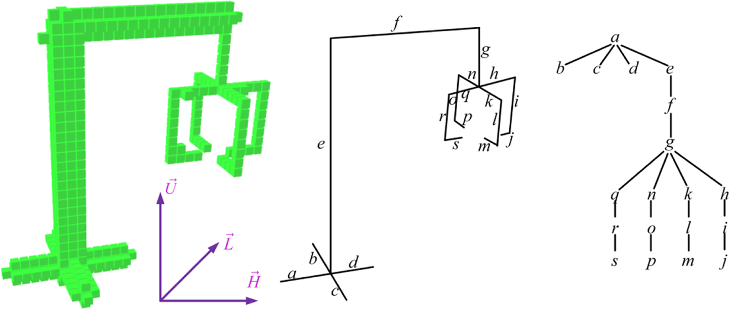
A manually designed L-system string for a crane-shape configuration.
L-system codes for each segment are given in Table 2. Brother nodes have magnitude subbranches, whose reconfiguration will develop in parallel using bracketed symbols. Although the same structure may have various describing symbols, we start from the root segment a and design codes for the whole structure, as shown in equation (3)

L-system symbols for each segment in Figure 11.

As shown in Figure 12, the self-reconfiguration develops in the growth pattern, including the growth in length and extension in radius. For the development in length direction, turtle modules attach mobile module as new turtle module at the length direction. At the same time, turtle modules also need to attach mobile module as structure module for extending segments in radial direction. As given in Figure 6, a turtle module only handles extension in the 2-D plane that is perpendicular to the length direction and centering on itself. Only when having all modules for radius

Self-reconfiguration to the crane-shape configuration in Figure 11.
Each simulation is repeated 10 times, and all converge to the desired configurations. The successful self-reconfiguration verifies the functionality of designed CA rules and proposed algorithm.
Experiments
The proposed mechanism is also verified on physical Seremo robotic systems. The Seremo robotic modules are 2-D moving robots. Compared with SCM in 3-D, the coordinate system in Seremo modules has the axis Up fixed to a global direction, as shown in Figure 13. Gradient information only translates between four connecting faces and only axes Head and Left may have gradient direction. No motion planning along axis Up is made.

The coordinate system of Seremo modules.
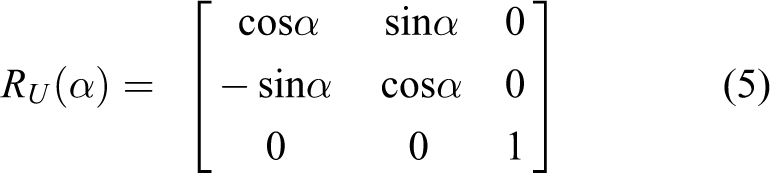
L-system symbols are designed in a turtle coordinate, which must be maintained in different modules to execute turtle interpretation. Compared the translation between 3-D SCM in equation (1), physical Seremo modules can only pivoting along axis up. The rotation matrix 
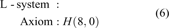
A simple L-system without reproduction rules is designed in equation (6). The simple L-system describes a single line segment using only one symbol H with length
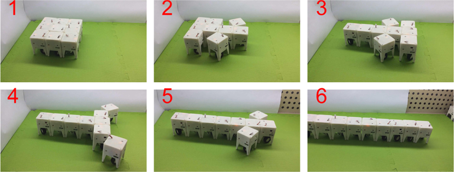
An experiment of self-reconfiguration from a lattice structure to a line shape.
equation (7) is an L-system with bracketed symbols and one reproduction rule. Figure 15 shows the corresponding self-reconfiguration process to a branching structure. This experiment verifies the branching character from bracketed symbols and rewriting work during interpretation. The module does rewriting work and extends the L-system string when interpreting the processor X. New generated symbols direct the following reconfiguration to a branching structure.
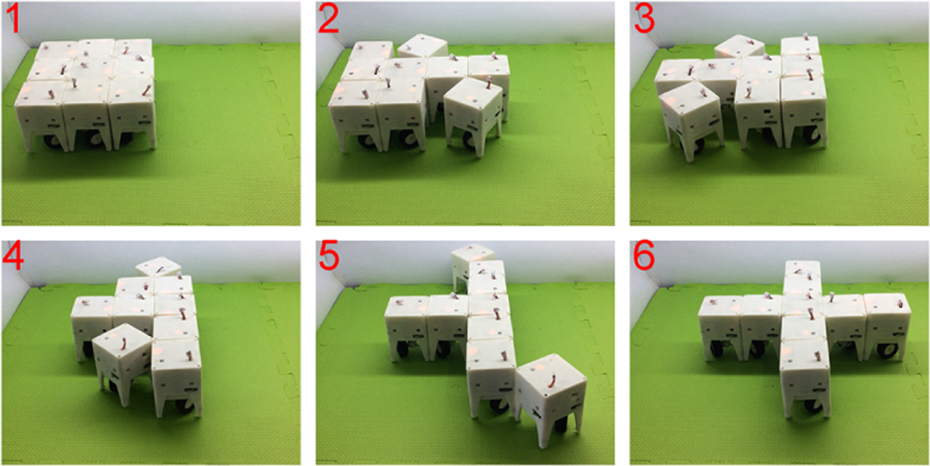
An experiment of self-reconfiguration from a lattice structure to a cross-shaped configuration.
Both experiments are repeated 10 times and all experiments converge to the desired configuration. This verifies the functionality and convergence of proposed algorithm
Results and discussion
A mechanism is proposed for decentralized self-configuration of MSR robots. L-systems are introduced for describing the topology of target configuration and CA for local motion planning. Besides the use of L-systems for description of target configuration, 35 the main novelty of this work is combining cluster-flow locomotion by CA and local predictions by interpreting global description by L-systems for distributed self-reconfiguration of modular robots.
A simplified set of CA rules is designed with only two rules. Compared with existing work on CA for MSR robots, we focus on local motion planning and simplify the rules in numbers. This set of rules is effective in both experiments on physical Seremo robots and self-reconfiguration simulations for branching configurations.
L-systems are introduced to describe global targets for the distributed self-reconfiguration. Turtle interpretation translates global description to module-level predictions. To recruit new modules to the expanding fronts in this construction process, gradient information is propagated locally between neighboring modules. Mobile modules will then climb this gradient direction according to local movement operations described by two CA rules. Local predictions from interpretation on systems are practical on physical robots. This is an improvement to existing work about distributed self-reconfiguration. 24
Through simulations and experiments, the designed mechanism is validated in self-reconfiguration for determined configurations. Our robots achieve the motion of 3-D SCM in 2-D by pivoting motion, including convex and concave transition and linear motion. This physical robot has all required abilities for local communication and independent working. Though not perfect, physical experiments verify the proposed mechanism to some extent.
There are also some problems needing further work. Firstly, there is no distribution strategy for controlling proper number of modules to each branch. Modules choose moving direction only by local gradient information, which may lead superabundant modules to the closest gradient source. As shown both in Figure 9, there are extra modules left at the end of some branches. Finished branching segments have no gradient source modules. Gradients by turtle modules in unfinished branches will translate and lead the movement of those extra modules, which then move long distance to other unfinished branches. This phenomenon, including the translation of gradient and movement of modules, may reduce the speed of self-reconfiguration.
Secondly, the currently used L-systems and reproduction rules are still manually designed. It is difficult to construct L-system rewriting rules, which can capture a given configuration. This is called the inference problem 50 –52 in the theory of L-systems. This limits the autonomy of robots in facing uncertain tasks or environments. We will focus on the source of configurations and their automatic expression using the fractal theory and evolutionary method learned from the nature. It is our aim to make a self-adaptive and self-reconfigurable robot functioning in the real world.
Footnotes
Declaration of conflicting interests
The author(s) declared no potential conflicts of interest with respect to the research, authorship, and/or publication of this article.
Funding
The author(s) disclosed receipt of the following financial support for the research, authorship, and/or publication of this article: This work was supported by National Natural Science Foundation of China (grant no. 61273316 & 61673137) and Self-Planned Task (no. SKLRS201501A02) of State Key Laboratory of Robotics and System (HIT).