
Abstract
This article presents a review on trends in modular reconfigurable robots, comparing the evolution of the features of the most significant robots over the years and focusing on the latest designs. These features are reconfiguration, docking, degrees of freedom, locomotion, control, communications, size, and powering. For each feature, some of the most relevant designs are presented and the current trends in the design are discussed.
Introduction
A module can be defined as a piece or a set of pieces that are repeated in a construction of any kind to make it easier, regular, and economic. Thus, a robotic module is a “module that performs, totally or partially, typical tasks of a robot, and that has the ability to interact with other modules.” 1 Consequently, a modular robot is a robot composed of modules, that is, “a robot composed of parts that have independent functionalities but are able to interact with each other in one or more ways, resulting in an entity with new capabilities.” 1
Some of the main advantages of using modular robots are to provide the system with versatility and configurability (either through manual or autonomous reconfigurability), to increase fault tolerance, to make the system scalable, and to reduce the production cost as only one or few module types need to be mass produced and therefore eliminating the need for assembly between parts.
The origins of modular multiconfigurable robots are known to have started in 1990 with CEBOT (Cellular Robotic System), 2 from Nagoya University. CEBOT is a dynamically configurable robot that has the capability of self-organization, self-evolution, and functional amplification (ability of a system to coordinate together to accomplish tasks that cannot be achieved by individual units by themselves). The history of modular robots goes even back to 1972, when active cord mechanism (ACM) 3 was created. It was the first robot to use principles of serpentine locomotion, mimicking gait of an actual snake. Although in its origin version, ACM cannot be classified as a modular multiconfigurable robot, it was a milestone during its development. Subsequent versions of ACM (ACM-R2 to ACM-R5) are examples of chain-type modular robots.
Since then many modular robots have been built: Fracta, 4 Molecule, 5 Crystalline, 6 Polybot, 7 M-TRAN, 8 CONRO, 9,10 Telecube, 11 Atron, 12 YaMoR, 13 Superbot, 14 Molecube, 15 CHOBIE, 16 Y1, 17 Roombots, 18 iMOBOT, 19 Sambot, 20 Pebbles, 21 THOR, 22 Ubot, 23,24 Cross-ball and Cross-cube, 25 Symbricator (Symbrion + Replicator), 26 Microtub, 27 SMORES, 28 Transmote, 29 M 3 Express, 30 CoSMO, 31 M-Blocks, 32 Kairo-3, 33 the educational versions Mobot and Linkbot, 34 PetRo, 35 ReBis, 36 ModRED, 37 Hinged-Tetro, 38 Alligator, 39 and Fable II. 40
Modular robotics is a research field widely studied at the moment. It has been extensible reviewed in many publications. 41 –44 Most reviews present the most important features of modular robots in a linear manner. The goal of this article is to (a) describe in detail some common features of most modular robots, (b) review how they have evolved over the years, and (c) show current trends. In this article, we focus on individual features in modular robotics such as reconfiguration, docking, degrees of freedom (DoF), locomotion, control, communications, size, and powering. We have analyzed these features from the dawn of the field of modular robotics but focusing on the more recent prototypes (up to 2015).
This article is organized as follows. Reconfigurability of a modular robotic system, categorized into self-reconfiguration and manual-reconfiguration, is presented in the second section, followed by a review on various docking mechanisms in the third section. The fourth section reviews DoF in unit modules, and the fifth section presents an overview on different modes of locomotion and different kinds of gaits commonly seen in modular robots. A review on controllers in modular robotics is presented in the sixth section, categorizing controllers based on type, homogeneity, and scalability. Communication systems and protocols commonly used in modular robotics, both intramodule and intermodule communication, are reviewed in the seventh section, while features such as size and commonly used and potential power-source for modular robots are reviewed in and the eighth and ninth sections, respectively. Each section has a subsection called “Trends summary” showing the trends in each feature. Finally, content of the article is summarized, and key points presented in the article are highlighted in the tenth section.
Reconfiguration
Reconfigurability refers to the property of a system to be configured in different ways, without considering the means of reconfiguration. Modular robots can be generally classified based on their configurable capabilities into manually configurable and self-reconfigurable (auto-configurable) systems. 45 Self-reconfigurable modular robots (SRMR) are those that are able to change their configuration on their own, while in manually-configurable modular robots, reconfiguration has to be done externally (i.e. by an operator).
Self-reconfigurable
Modular robots are usually classified into chain-type, lattice-type, or hybrid-type architectures. 41 Chain-type architectures consist of modules that are connected together in a linear or tree topology. This structure can fold-up to become space filling, but the underlying architecture is serial.
From the very beginning of modular robotics, there has been a clear tendency to build chain-type modular robots that are able to autonomously change their configuration into wheel, quadrupeds, snake, worm, and so on. Polybot 7,46 M-TRAN I, II, and III 8,47,48 Superbot, 14 iMOBOT, 19 Ubot 23,24 SMORES, 28 Transmote, 29 CoSMO 31 , and the educational versions Mobot and Linkbot 34 are examples of chain-type systems. Modular robots which are designed to navigate in different and unknown environments (e.g., in rescue or space exploration missions), where a modular robot needs to change its configuration to avoid obstacles, to climb up or down steep slopes, to pass through narrow openings, and so on, follow the chain-type architecture.
A lattice-type robot has modules that are arranged in a regular three-dimensional (3D) pattern, such as a cubical or hexagonal grid. Lattice-type modular robots are inherently self-reconfigurable because reconfiguration is their only means of locomotion. From Molecube, 15 Crystalline 6 and Molecule, 5 Telecube, 11 CHOBIE I and II 16, Atron 12,49 Cross-ball and Cross-cube, 25 and M-Blocks, 32 we find a clear tendency in these modular robots to find the optimal reconfiguration algorithms to increase speed of reconfiguration. A special use of lattice-type modular robots as self-reconfigurable furniture is presented in Bonardi et al. 50 with Roombots.
Hybrid-type architectures have features of both lattice-type and chain-type architectures. Some modular robot can be classified as hybrid-type because they can be configured both as chain and as lattice structures. M-TRAN 8,47,48 Superbot, 14 SMORES 28 , and Roombots 50 are examples of hybrid-type modular robots.
Some modules have the ability to move independently (micro-locomotion): An Atron module can use its module hemispheres as wheels. CoSMO modules have the ability to independently locomote in all main direction. An M-Blocks module is not only able to move to an adjacent position in the grid structure, but it can jump and connect to modules that are at several modules distance away in the structure.
Subcategories under SRMR are metamorphic robots, self-replicating robots, and nested reconfigurations, which are explained in the following subsections.
Metamorphic
A metamorphic robot is a system that “consists of multiple identical robotic cells in an underlying lattice structure which can disconnect/reconnect with adjacent neighbors, and slide, pivot, or otherwise locomote to neighboring lattice points following prescribed rules to change the global shape of the system.” 51 The first metamorphic robot was developed in 1994. 52 Generally speaking, most self-reconfigurable robots are metamorphic. They can change their configuration into wheel, quadruped, snake, worm, and so on.
Self-replicating
A physical system is self-replicating if it can construct a detached, functional copy of itself (provided they have the necessary modules). Self-replication differs from self-assembly, in which the resulting system is not able to make, catalyze, or in some other way induce more copies of itself. The term self-replicating was coined along with the development of Molecube modular robotic system 53 but has not been used ever since.
Nested reconfiguration
Nested reconfiguration is an emerging research area in modular robotics. This design concept utilizes individual robot modules with distinctive reconfiguration characteristics (intrareconfigurability), which are capable of combining with other homogeneous/heterogeneous robots (interreconfigurability). The objective of this approach is to generate more complex morphologies for performing specific tasks that are far from the capabilities of a single module or to respond to programmable assembly requirements. 38
Hinged-Tetro 38 is a mobile robot that is able to transform itself into one of any seven one-sided tetrominoes (i.e., the Tetris pieces) in a straightforward way and combine with other modules.
Manually configurable
Manually configurable modular robots are modular robots that have to be assembled by the operator. They present the advantage that the docking mechanism can be much simpler (not autonomous). In some applications, like pipe inspection, it is not useful to have self-reconfiguration because it is not possible to do so due to the lack of space. Although tendency in modular robots has been toward self-reconfiguration, several manually configurable robot designs have appeared in the past decade or so. Examples of these types are CONRO, 10 Microtub, 54,27 Fable II, 40 PetRo, 35 and Alligator. 39
The Fable II 40 robot consists of two types of modules (active and passive) that users can assemble into different morphologies. Active modules hold the microcontroller, onboard power, and a radio device for wireless communication with the PC. Passive modules are plastic moulds used to give robot a structure. Morphologies ranging from a robotic arm to quadrupeds can be achieved through manual configuration.
PetRo (which stands for Pet Robot 35 ) is a tetrapod modular throwable, self-assembling, and reconfigurable pet robot for use as a companion pet and for search and rescue operations. Each module can move independently (rotation and translation), and several modules together can perform dog-, horse-, and -ike locomotion.
The Alligator-inspired modular robot 39 is a system composed of 14 modules and has a fixed configuration. Thanks to a dissembling system, small robots can be automatically released from the larger robot frame and swim around with independent actuation system.
Snake-like modular robots (usually chain-type) are robots that mimic serpent locomotion and are composed of one or two types of repeated modules. In this system, it is possible to change position of modules, usually through manual-reconfiguration, but the configuration remains the same. Among snake-like robots, we find ACM I to V 3,55,56,57 Wormbot, 58 KAIRO-3, 33 ReBiS, 36 Modular Amphibious Snake-like Robot, 59 and Lola-OP. 60
KAIRO-3 33 is the latest version of the KAIRO series, which are biologically inspired by inchworm and snake organisms. KAIRO-3 can be classified as a heterogeneous modular robot because it consists of two fundamentally different types of modules: drive modules and joint modules. ReBis 36 is a modular robots capable of switching between serpent-like and bipedal gaits.
Reconfiguration trends
Since the beginning of modular robotics, there has been a clear trend toward build self-configurable systems. Only some systems like CONRO and Microtub were designed for manually reconfigurable. But in the past few years, both design options have been equally chosen. Kairo3, PetRo, FableII, and Alligator on the manual configuration side and Hinged-Tetro, Mobot/Linkbot, M-Blocks, and CoSMO on the self-reconfiguration side show that both design choices have been equally opted for nowadays. Table 1 provides a summary on reconfigurability in modular robotics.
Reconfiguration summary.

Docking
A docking element is one of the most important parts of a modular robot. It allows a module to physically connect to two or more modules, resulting in the formation of a larger robotic configuration for performing a certain task. Some docking systems also facilitate communication and power transmission between modules. Based on the level of autonomy of the connecting mechanism, a modular robotic system can be classified as either manually configurable or self-reconfigurable.
It is widely agreed upon that a good and reliable docking system would possess several of the following properties
61,62,63
: Size: A connector should be as small and thin as possible so that a module can house several of them, which in turn increase the possible number of configuration of the system. Mechanical strength: Must be strong enough to withstand any impact or motion in the foreseeable application of the system such that the overall configuration stays intact at all times. Mechanical strength of a configuration is said to be the weakest strength between two modules in the configuration. Communication: To function autonomously and for the purpose of self-reconfiguration, connected modules in a configuration need to be able to communicate with each other directly, without having to rely on an external source. Power sharing: Power sharing mechanism between modules in a configuration prolongs operation time of the entire system by transferring power from low-functional modules to high-functional modules in the configuration. In heterogeneous systems, where primary function of some modules would be to store and disperse power among other connected modules, a reliable power sharing mechanism is mandatory. Reversibility and repeatability: Self-reconfiguration does not only require easy connection between modules but also ability to easily disconnect. This process should be repeatable for several cycles. Connection and disconnection speed: Medium to complex reconfiguration tasks would need several steps of connection and disconnection between modules. Hence speed of doing so is an important factor. Tolerance to misalignment: There exists a trade-off between designing a modular robot that accurately aligns itself for docking and a docking system that is tolerant to misalignment. Power consumption: Docking and undocking process should be as energy efficient as possible, as available power in a module is usually limited. Gender and orientation: Modular robotic systems with gendered and orientation-dependent docking systems limit the possible number of configurations. So an ideal docking system is genderless and orientation independent. Unilateral connection/disconnection: A docking mechanism that allows a module to connect to and disconnect from other modules independently and ensure that the module and/or the configuration continues to operate in case one of the connectedmodules fail.
A summary of these properties is shown in Table 2.
Properties of an ideal connector.

Magnetic
Modules of M-TRAN I 8 and M-TRAN II 64 systems employ permanent magnets as connection mechanism, while shape memory alloy (SMA) coils and a nonlinear spring is used for expelling a connected module. In Fracta modules, 4 a layer of electromagnet, sandwiched in between two layers of permanent magnets, are used as connection mechanism. Each layer has three magnets, arranged in 120° intervals. The two permanent magnet layers are arranged parallel to each other, while the middle electromagnetic layer is offset by 60°. IR transmitter/receiver pairs are embedded in the magnets, along with a serial asynchronous protocol, and are used for communication between Fracta modules.
Telecube modules 11 feature pairs of switching permanent magnetic device and magnetic metal plate, placed diagonally, as connection mechanism. Criss-cross-shaped SMA wire and springs are used for undocking. In this docking system, connecting and disconnecting can be achieved unilaterally. The docking surface also holds two pairs of IR transmitters and sensors for communication between connected modules, three electrical contact switch, and PCBs. Positional misalignment of up to 3 mm is reported to be tolerated in this docking system.
SMORES 28 modules employ four magnets (two north-pole and two south-pole) arranged alternatingly around the docking face, at an interval of 90° from each other. Each SMORES module has three active connectors and one passive connector. Active connectors have one continuous rotational DoF, which they can align themselves to coincide with the opposing connector for establishing a connection. A mechanical “key” system is used to undock a module from its neighboring connector unilaterally. Undocking is achieved by inserting the “key” into the connected modules’ docking port, holding it in place, while rotating its connector at the same time to break the magnetic force. Energy is needed only for undocking.
In lattice-type M-Blocks system, 32 cube-shaped modules employ 2 diametrically polarized cylindrical magnets on each of the 12 edges, in addition to 8 axially polarized disk magnets on each of the 6 faces. The edge magnets can rotate freely, allowing two modules to pivot around the connected edge, while face magnets aid in correcting misalignment between connected modules. Face magnets are arranged in a eight-way symmetrical pattern, making the connection mechanism genderless. An inertial actuator within the module facilitates module undocking for reconfiguration.
Fable II modular robot 40 presents a genderless docking system that is 90° symmetric. Two different (small and medium) size connectors, which are cross-compatible, are used in this system. The connector uses a pair of (north and south pole) magnets, a flange, and a groove per 90° segment of the circular connector. An additional ring of magnets is used in the medium size connector to ensure compatibility between different size connectors. Only manual disconnection between modules is possible in this system.
Electromagnetic
Electromagnetic connectors are similar to magnetic connectors, except that electrical power is needed to create and maintain the magnetic field, which can be energy inefficient compared to magnetic connectors. An obvious advantage is that the polarity of an electromagnet can be interchanged, meaning that connection between any two docking units can be established without having to reorient the docking surface. Also, unlike with a magnetic connectors, an additional mechanism for undocking or repelling a connected module is not needed.
Fracta modules use a combination of magnetic and electromagnetic connectors, but Molecule 5 modules were one of the first to feature electromagnetic only connectors, where each module has five connectors, and the electromagnets used are powerful enough to support the weight of a connected module.
Four custom-fabricated electro-permanent magnets are used per Robot pebble modules 65 as connection mechanism. The connection mechanism provides four-way rotational symmetry, and electric-current is only used for switching polarity of the electro-permanent magnets, for docking and undocking, respectively, and not for maintaining the connection. Electro-permanent magnets are also used for communication and power-transmission between connected modules.
Electrostatic
In electrostatic type of connectors, electrodes made up of flexible aluminum foil and coated with dielectric film are used, 66 and docking systems are composed of electrodes glued to plastic panels and laid into multiple columns on the face of the module. Connection between modules is established by applying voltage to the face of the module. According to Karagozler et al., 66 power-transmission and communication between connected modules is achievable in this kind of docking system, albeit not currently efficient.
Electromechanical
Electromechanical connection mechanism is used in PolyBot G2 modules. 67 The connector is composed of (a) electrical connection components; (b) pins and holes, for establishing connection between modules; (c) SMA wires actuated retracting spring system for breaking the connection; and (d) IR transceivers for communication between modules. An important feature of this connector system is that it requires energy only during the process of connection and disconnection and does not consume any energy while in connected state.
CONRO modules utilize a similar connection mechanism, 68,69 where each module has one active connector consisting of two holes and a latching system actuated by a spring for making and holding a connection, and three passive connectors consisting of two pins each that can penetrate the holes of a female connector of another module. Unilateral disconnection is possible in this connection mechanism which in Sproewitz et al. 70 is described as a capability of the system to self-heal.
Another example of SMA actuated disconnection mechanism is found in Alligator-inspired modular robotic system. 39 Here, two locking blocks are used for connecting a head and tail of a module to the larger robot frame. Lubricating grease is used to reduce friction while operating in water, as well as to waterproof SMA, so as to reduce its power consumption while actuated in water.
According to Kurokawa et al., 64 SMA wires-based docking systems are time consuming and energy intensive. So docking systems in M-TRAN III modules were designed to be gendered, utilizing motorized hooks for connecting two modules. This docking system also carried IR transceivers for communication between connected modules. The docking system is designed to overcome positional misalignment between modules, and electrical power is needed only during connecting and disconnecting process and not while in connected state.
A similar type of connector is the active connection mechanism (ACM), 70 which is a genderless docking system containing both motorized hooks and holes. ACMs are designed to both connect and disconnect actively and features a 90° symmetry. This docking system is designed for relatively larger and heavier robot modules and so features high load capacity, force and torque, and can also overcome large misalignment between connecting modules but at the cost of increased complexity and size of the docking system. A modified version of ACM is implemented in the Roombots modules, 18 which feature fewer number of motorized hooks, resulting in decreased load capacity compared to the original version. In both version of ACM, electrical power is needed only during connecting and disconnecting process and not while in connected state.
Worm-driven docking hooks are used as connection mechanism in Sambot modules. 20 Embedded IR transceivers and mechanical docking touch switches in the docking system are used for finding, aligning, docking, and locking process for self-assembly between two Sambot modules.
A similar docking mechanism with worm-driven motorized hooks is featured in ATRON modules. 71 The connection mechanism is gendered with three active hooks that can connect and hold on to two passive stainless steal bars, which are rigidly integrated onto the surface of an ATRON module. The authors describe this connection mechanism as point-to-point connection system, in contrast to surface-to-surface connection system, which is generally featured in most modular robotics systems.
Liedker et al. 72 present a genderless docking system called Cone Bolt Locking Device (CoBoLD), used in Symbrion and Replicator 73 robot modules. This docking system features four cone-shaped bolts and four holes per docking unit, in addition to a locking wheel to hold cone bolts in place. It is an active docking system that features a 90° symmetry and can handle positional and orientation misalignment of up to 5 mm and 20°, respectively. The docking system also holds pressure sensors and nine electrical contact points, which are 90° symmetric as well, for power transmission and communication between connected modules.
SINGO connectors used in SuperBot modules 74 feature a connection mechanism composed of four locking “jaws” that can move linearly back and forth (or outward and inward) on sliding rails, from the center to the edge of the docking face. Each “jaw” is shaped like an arrow head (i.e. with a pointed head and an inverted “V” shaped tail) and arranged with a 90° symmetry such that the head of the jaws point to the center. Connection between two such connectors can be established when (a) either the heads of the first connector’s “jaws” clinch the tails of the second connector’s “jaws,” moving inward or when (b) the tails of the first connector’s “jaws” clinch the heads of the second connector’s “jaws,” moving outward. This connector is genderless, does not consume energy while in connected state, and can operate bilaterally as well as unilaterally to both establish and disengage connection with another module, giving self-assembling and self-healing capabilities to the modular robotic system.
M 3 Express 30 features a hybrid docking system that carries a pair of permanent magnets and a pair of steal screws for magnetic connection, in addition to four spring loaded tapered pins and four holes, arranged in pairs at 90° from each other, for mechanical connection. Tapered pins and steal screws, actuated by a miniature RC servo, can move in and out of the docking surface for establishing and breaking connection with the opposing connector, respectively. The connector is genderless, 180° symmetric, and does not consume power while in connected state.
Docking trends
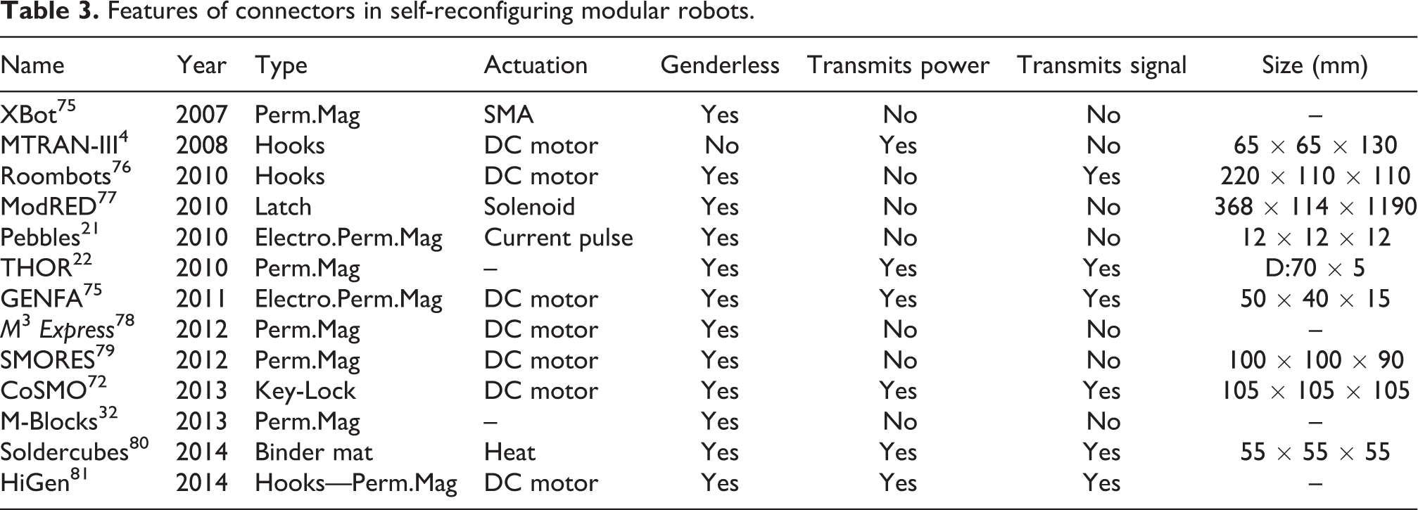
Docking system is one of the most important feature in a modular robotic system. Some of the most common types of docking mechanisms used in modular robotics have been presented in this section. Magnetic and electronmagnetic connectors were featured in some of the earliest modular robotic systems. Most of the recent systems feature magnetic- and electromechanical-based docking systems. Magnetic-based docking systems are common among manually configurable systems like Fable II 40 and M 3 Express, 30 while electromechanical-based docking systems are used in self-reconfigurable systems like Symbricator and Roombots. A summary of the features of connectors in self-reconfiguring modular robots is shown in Table 3.
Features of connectors in self-reconfiguring modular robots.
Degrees of freedom
Mobility and adaptability are desired features for any robot to overcome challenges that may arise during normal operation. These characteristics are mostly determined by the DoF of the complete system. The more DoF it has, the more suitable the mechanism is to adapt its shape to different environments and to perform complex motions. But also, complicating the mechanical, electrical, and control design of the robot. Owing to the ease a modular robot has to change its configuration by adding or subtracting modules, it is unreasonable to speak about the overall DoF of a modular robot. Therefore, this section will focus instead on the DoF of the modules or basic units that form these mechatronic systems.
Two approaches or trends can be observed in recent designs of modules, which will be reviewed in the following subsections. Chain-type modular robots are designed to be light-weight, mechanically simple, easy to control, and to be connected in a tree structure. On the other hand, lattice-type modules can be combined to create 3D structures with high degrees of movement but with a drawback in terms of weight and power consumption.
Chain-type modules
Chain-type modules typically have one or two DoF. A single module by itself cannot perform many tasks. But when combined with other modules, the resulting structure can perform complicated movements and tasks. The strategy behind the design of these elements is the combined effort of all the modules to achieve the goals. By implementing a small number of DoF in each element, the control of the module remains simple, the design can be reduced, and so be easily replicated. Moreover, the control software can manage a great number of these modules due to the simplicity of the electromechanical design, and power consumption of each module can be optimized more easily. This trend can found in chain-type modular robots.
Microtub 54 is composed of modules of up to two DoF, and thus these are a good examples of the chain-type modules. Individual module cannot function on their own, but when combined with other modules, the resulting chain-type robot can perform complicated tasks such as inspection of and navigation inside pipes and locomotion on open 2D surface. Also, the possibility of different combinations of modules provides the system with great versatility to overcome different challenges as explained in Brunete. 84
ReBis 36 is another example, designed by Rohan Thakker et al. Modules are connected sequentially forming a chain. These are designed with only one ±120° revolute DoF. However, despite the apparent simplicity of the design, ReBiS is flexible enough to produce both a serpentine gait and a bipedal gait.
Typically, these modules implement a rotational joints. Compared to linear joints, rotational joints have been proven to provide a highest rate of mobility versus the weight of the required equipment. Also, volume of joint actuators are smaller, reducing in size of the module. In addition, these are mechanically easier to implement, as they only require a motor to provide the turning movement, and a gear box to adjust the generated torque, while other joint types would need additional equipment to transform rotational motion into other types of movement. Depending on the design, this joint can either be 360° in range or limited to a certain angle.
For example, previously mentioned ReBis modules use a single revolution joint per module. However, if modules are connected in such a way the rotational axis of consecutive modules are orthogonal, the robot is able to reach any point in 3D space. 36
Lattice-type modules
These modules are capable of connecting simultaneously with more than two modules to form complex structures with a high DoF. These systems are intended to be able to adapt to a wider range of scenarios compared to chain-type modules and so they are used in lattice-type and hybrid-type modular robots.
To achieve this level of flexibility and adaptability, lattice-type modules are normally equipped with more than one DoF. However, THOR 22 and CoSMOS 31 modules, which have a single DoF, are exceptions. Another characteristic feature of lattice-type modules is the greater number of docking systems, embedded on several faces of of a module. This feature allows a module to be attached to multiple neighboring modules at the same time. Nonetheless, the final design of these modules is heavier and mechanically more complex than the chain-type modules. Also, the control software implemented requires more powerful microprocessor, and thus more power consuming, to carryout processor-intensive algorithms to control all the elements.
To this end, heterogeneous systems are being explored to provide advantages of a homogeneous lattice-type module, by combining several simpler and less demanding modules with many different types of functionality. However, this field of research is not as studied as homogeneous systems as shown in Table 5.
Comparing between Tables 4 and 5, it could be noted that the focus in the recent years has been on lattice-type and hybrid-type modular robotic systems, as most of the recently developed modular robots fall under this category. Recent trends point toward developing lattice-type or hybrid-type systems with two or three DoF modules, and independent locomotion (micro-locomotion) capability, and also to build highly adaptable modular robots with the ability to programmatically assemble and disassemble.
DoF of chain-type modules.

DOF: degree of freedom.
DoF of lattice-type modules.

DOF: degree of freedom.
The above holds true in the case of M 3 Express (Modular Mobile Multirobot) 30 by Kevin C. Wolfe et al., which is a hybrid-type robot that is capable of self-assembling to form into either chain-type or lattice-type structures. A M 3 Express module has three wheels that serve both as a docking unit and as a micro-locomotion system. With three DoF, a module can operate and locomote independently and self-assemble to form flexible polyhedral structures.
However, there are lattice-type systems with only one DoF per module. CoSMOS 31 (Colletive Self-Configurable Modular Robot) by Jens Liedke et al., at the Karlsruhe institute of Technology, is an example. Each module is composed of two halves that can bend over each other by ±90°, and because of the docking units embedded on four of the six faces of the modules, these can be assembled to either form a chain or a grid structure.
Robot Pebbles 21 by Kyle Gilpin et al. is a lattice-type modular robot and needs to be highlighted here, as modules in this system have no DoF. Each cube-shaped module can attach to each other through custom-designed electropermanent magnets. Through self-disassembly, they can adopt to any kind of shape easily. Each module is 12 mm in size, about 3.75 times smaller than its predecessor Miche. 42 However, unlike its predecessor, Plebbes does not have disassembly capability given by the rotating magnet of Miche.
Similar to chain-type modules, lattice-type modules are also mainly equipped with rotational joints. Typically, the DoF are located in the docking systems as seen in Cross-ball system. 25 Nonetheless, other designs like iMobot 19 change the shape of the module by means of joints that connect the two halves of the unit.
DoF trends
The DoF of the modules or basic units of recently presented modular robot have been analyzed in this section. Two main trends have been presented: chain-type and lattice-type designs. Chain-type modules tend to have one or at most two DoF, with adaptability in the system coming as a result of aggregated DoF of multiple modules in the configuration. On the other hand, lattice-type modules tend to have as many DoF per module as possible, giving it the abilities to easily adapt to the environment, to move autonomously, and to self-reconfigure.
Locomotion
In modular robots, locomotion is achieved through coordinated action of individual modules. In chain-type modular robots, locomotion is achieved through continuous actuation of its motorized DoF, whereas in lattice-type, locomotion comes about as a result of continuous self-reconfiguration. Gait produced by a modular robotic configuration depends on the morphology of the configuration.
Limbless locomotion
Caterpillar
Caterpillar gait is the most common gait in chain-type modular robots. It has been implemented in virtually all the modular robotic platforms discussed in this article M-TRAN, 47 CONRO, 87 Y1, 88,17 Micritub, 27 etc. It is a 1D gait inspired by crawling locomotion of a biological caterpillar. The robot can move either in forward or backward directions on a straight line, and it is commonly implemented in linear configurations. The gait is achieved by oscillating only the pitch-axis actuator(s) of connected modules, with consistent phase-shift in oscillation between consecutive modules. This produces a traveling wave along the length of the configuration, which results in propelling the robot forward in the direction of the traveling wave.
Lateral-shift
This is a 2D gait and can be implemented in linear configurations with alternating pitch-axis and yaw-axis actuators, along the length of the configurations. The gait is inspired by and replicates locomotion of sidewinder snake species. The gait is achieved when adjacent pitch-axis actuators in the configuration oscillate with consistent phase difference between them, while adjacent yaw-axis actuators do so as well, although phase-shift relation between the two sets of pitch-axis and yaw-axis actuators is independent of each other. Amplitude, offset, and phase-shift parameters of individual oscillations determine the shape, size, direction, and orientation of the gait. Lateral-shift gait is demonstrated in CONRO, 87 Microtub, 27 and Y1. 17
Inchworm
Inchworm gait is achieved in linear configurations by contracting and elongating the length of the configuration. In Brunete et al., 27 inchworm gait inside pipes of varying diameters has been implemented in the heterogeneous multiconfigurable modular robot Microtub, using two kinds of modules: support module and extension module. A support module, the outer surface of which is partially rubber, when actuated expands outward, firmly holding the module to the inner-surface of the pipe. An extension module, which has a linear actuator, when actuated can both extend and rotate in the yaw-axis. Inchworm gait can be achieved in a configuration which has at least two support modules with one extension module in between them. The gait is achieved by repeating cycles of actuating front and rear support modules alternatively, holding and realizing the module to the pipe, while contracting and elongating the extension module, propelling the robot forward.
Wang et al. 89 have studied the gait kinematics of a biological inchworm and replicated the same on a linear modular robotic configuration with suction cups. Two kinds of modules are used: joint module with 1DoF actuator in pitch-axis and attachment module with an active suction cup for attaching the module to vertical surface. A linear configuration is formed by connecting three joint modules serially, along with two attachment modules at either end. Inchworm gait on a vertical surface has been successfully demonstrated in this work.
In Russo et al., 90 inchworm gait has also been achieved in a linear configuration containing three Scout modules. The gait is achieved by repeating cycles of contraction and elongation of the body length of a linear configuration, through coordinated actuation of module’s DoF actuators. Here, unlike in the previous two cases, the gait has been demonstrated on horizontal surface, in open air.
Walking locomotion
2D walker
In Ranganath et al.,
88
a six-module 2D quadruped configuration, with each limb having only 1 DoF, is presented (Figure 1). The four limb modules oscillate in the pitch-axis, while the two spine modules oscillate in the yaw-axis. The robot can walk forward, backward, move on an arc, rotate on its axis, and move laterally left or right. When diagonal pairs of limbs (e.g., Limb1 and Limb3) oscillate in phase, while maintaining a phase difference between the two pairs of limbs (i.e.,
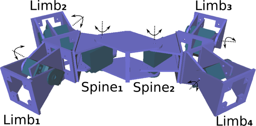
2D quadruped configuration with four Limb modules and two Spine modules.
Another example of a 2D quadruped configuration is presented in Russo et al. 90 Five Scout modules are used in this configuration, where four modules form limbs of the quadruped, while the fifth module is the torso module, holding the rest of the modules together. Locomotion in any direction on a 2D plain is achievable in this configuration, and the authors have experimentally proven its ability to climb over obstacles 5 cm high and at a slope of 90°.
3D walker
3D quadruped configurations modules have been presented in 91 (CONRO) and 92 (Roombots), where each limb has two DoF. Each limb has one hip joint (oscillating in pitch-axis) and one knee-joint (oscillating in roll-axis). Here, each limb needs to coordinate with other limbs in the configuration (inter-limb coordination), as well as joints within a limb (hip joint and knee joint) need to coordinate with each other (intra-limb coordination), to produce a walking gait. The spine module(s) in these configuration oscillate in yaw-axis, enhancing the produced gait. In 91 an hexapod configuration is created by appending the quadruped configuration with an extra-spine module and two limb modules. Similar to the 2D walker, walking gait is achieved in these configurations when diagonal set of limbs oscillate in phase while maintaining a phase difference between two sets of limbs.
A H-Walker is a 3D quadruped with multiple DoF limbs presented in 64 (M-TRAN II) and 93 (Superbot). Here the spine module is static, used only for connecting the limb modules together.
Rolling/Wheel-based locomotion
Rolling-track
Rolling-track gait can be achieved in a loop configuration, which is formed by connecting the two end modules of a linear configuration to each other, closing the loop. Experiments on this gait have been done in Støy et al. 87 (CONRO), Shen et al., 93 and Chiu et al. 94 (Superbot) with loop configurations of varying length. Loop configurations, depending on the number of modules, can take the shape ranging from an hexagon to a circle. Locomotion in this configuration is achieved by continuously changing the shape of the configuration by squeezing and realizing the shape of the loop. In Chiu et al., 94 steep slope climbing with a loop configuration has been demonstrated, where the loop is collapsed to maintain a low center of gravity.
Helicoidal
In Brunete et al., 27 authors have described experimenting with helicoidal gait on the heterogeneous chained robot Mictotub. The gait is achieved in linear configuration with a special module. This module has two parts (a rotating head and a body), and when the head of the modules is continuously rotated, it pushes the body of the robot forward in a helicoidal motion. This gait has been tested inside vertical and horizontal narrow pipes and in open air. This gait is very fast, but only locomotion in 1D is possible.
Differential drive
Differential drive is a two-wheeled drive system, where each wheel is actuated independently. Direction and rotation of locomotion comes about as a result of speed and direction of rotation of the two independently controlled wheels. In Kernbach et al., 95 track-based, screw drive-based, and omnidirection-wheel-based differential drive locomotion has been implemented in Symbricator modules Scout, Backbone, and Active Wheel, respectively, which gives independent locomotion capability for individual modules (micro-locomotion) as well as macro-locomotion as part of a larger robotic organism.
A Scout module has two independently driven tracks on either sides (left and right) of its quasi-cubical shaped chassis, which gives it the ability to move forward, backward, turn right, turn left, and to rotate on its own axis. In a Backbone module, two cylindrical screw drives placed in the front-bottom and rear-bottom side of its quasi-cubic chassis, and independently controlled by two motors, are used by the module to move in forward, reverse, left, and right directions as well as to turn left and right. An Active Wheel module has two pairs of omnidirection-wheels, placed perpendicular to each other, with four motors independently controlling the wheels. This gives the module ability to independently move forward, backward, right, left, turn right and left, rotate on its own axis, move on a arc, and also move in complex trajectories on a 2D plane through accurately controlling the four independent motors.
In Davey et al., 28 the authors have implemented a wheel-based differential drive system in SMORES modular robot for modules to move independently on relatively flat surfaces. The wheels, which also hold docking ports on its surface, are on the right and left sides of the cubic shape chassis of the module. Each module can move forward, reverse, turn left and right, and rotate on its own axis. This locomotion is necessary for modules to aggregate and align for self-assembly.
Self-reconfiguration-based locomotion
In lattice-type modular robots, locomotion is achieved through continuous self-reconfiguration. In a lattice structure, when modules at one end of the grid, by continuously connecting to and disconnecting with other modules on the outer edge of the structure, move to the other end of the grid, this results in the displacement of the entire structure. This kind of locomotion gives the notion of modules flowing on the ground, which is visually similar to locomotion of an amoeba or to that of a puddle of water flowing on a flat surface.
In Meng and Jin, 96 lattice-type modular robot Cross-cube modules are continuously reconfigured to produce flowing locomotion. An advantage of this locomotion is that a configuration can morph its shape to avoid obstacles or to move through narrow passage.
In Bonardi et al., 50 a Roombots module moves on a 2D grid, from an initial position to the goal position on the grid, through self-reconfiguration. Modules connect to the 2D grid surface, where each grid cell has a connector (ACM) similar to those on the module. A module connected to a grid cell, through its DoF motor actuation, can reach its neighboring cell, then connect to that cell, and disconnect from the previous cell. In this way, a module can move from cell to cell on a grid, moving from an initial to the goal location. Locomotion on a 3D grid surface has also been demonstrated in this work.
Locomotion trends
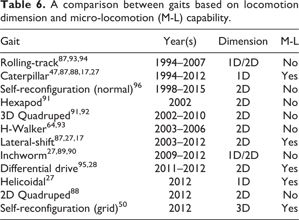
In the literature, a large variety of gaits ranging from simple creeping and crawling gaits, achievable in limbless modular robotic configurations, to walking and rolling gaits achievable in more complex 2D and 3D configurations, and locomotion through self-reconfiguration, exists. A clear trend in recent gaits in modular robots reflects on micro-locomotion aspect of the gaits, which provide independent locomotion capability to unit modules. Also, wheel-based locomotion for both micro- and macro-locomotion is a trend seen among more recent (post-2010) modular robotic systems like Symbricator, 95 Microtub, 27 M 3 Express, 30 and SMORES. 28 Table 6 compares all the gaits discussed in this section based on the dimension of locomotion, and the ability of a single module to achieve this gait in micro-locomotion mode.
A comparison between gaits based on locomotion dimension and micro-locomotion (M-L) capability.
Control
As per the literature, controllers in modular robotics are generally used for controlling locomotion and self-reconfiguration. These controllers can be broadly classified into Central Control (CC) type and Distributed Control (DC) type. In a CC-type controller, individual modules in a configuration receive high-level control signals from either a master module or an external source. On the contrary, in a DC-type controller, each module computes its own control signal based on its sensor readings and intermodule communication. Homogeneity is another aspect of controllers in modular robotics. If all the modules in a modular robotic configuration has the exact same controller (including identical parameters), then it is called as homogeneous controller and nonhomogeneous or heterogeneous otherwise. Scalability of a controller determines its ability to continue to function without any modifications, as the number of modules in the configuration grows.
Locomotion controllers
One of the earliest locomotion controllers for modular robots includes the gait table controller proposed by Yim et al., 7 where each column of the table contains a set of actions for a module in the configuration. The controller is homogeneous, since all the modules would have the entire gait table. A master module communicates with the rest of the modules in the configuration to synchronize transition from one row to the next, making it a central controller. The controller is not scalable.
A distributed, homogeneous and scalable locomotion controller for CONRO, 9,10 modular robots is proposed by Stoy et al. 87,91 It is a role-based controller, where a module decides/modifies its action, based on (a) its location in the configuration and (b) action of connected modules, facilitated by direct-local-communication among connected modules.
Digital hormone controller
Digital hormone method (DHM) 97,98 is a biologically inspired adaptive communication method developed by Shen et al., through which modules in a configuration can communicate state information with each other. Based on such communication, modules can decide/choose their action from a predefined gait table, and this in turn results in the emerged gait. If there is a failure of one or some modules in the configuration, or a change in configuration of the robotic organism, through adaptive communication such changes are taken into consideration locally, and the gait is adapted accordingly to suit the change in configuration. Locomotion in several CONRO configurations 9,10 and Superbot configurations 14 have been implemented successfully with DHM. In this control model, there is no central master module, so it is a DC. Also, the controller is homogeneous and scalable.
Sinusoidal controller
In Gonzalez-Gomez and Boemo, 99 simple phase-differed sinusoidal oscillators are used as locomotion controllers for two and three module configurations by Gonzalez-Gomez et al. Here, each module has 1 DoF, and so according to the authors, these are the simplest possible modular robotic configurations for producing 1D and 2D gaits, respectively. In Zhang et al., 100 two kinds of caterpillar gaits have been studied from a kinematic perspective and then replicated on linear modular robotic configuration, using phase-differed sinusoidal oscillators. The controller here is distributed but without any communication between modules for coordination. So time synchronization between modules is achieved by the internal clock of the module’s computing unit, and so the user needs to ensure booting all the modules at the same time. The controller is scalable, but it is not homogeneous since control parameters are preprogrammed based on the position of a module in a given configuration.
Central pattern generator
In vertebrates, locomotion is produced by a set of specialized neurons called central pattern generators (CPGs) 101 found in the spinal cord. These neurons have the ability to produce rhythmic output without neither central input from the brain nor rhythmic sensory input. Ijspreet et al. 102 and Pouya et al. 92 have used CPGs as locomotion controllers for configurations based on YaMoR 13 and Roombots 103 modular robots, respectively. In Roombots-based configurations, CPGs are used for producing both rotation and oscillatory motion of DoF motors. Each module is controlled distributively by its own CPG controller, the mathematical model of which usually consists of one or two neurons (nonlinear oscillator) per module. Modules are, based on the topology of the configuration, coupled in different ways with similar neurons of other modules in a given configuration.
A CPG-based controller is of DC type, as there isn’t a single module responsible for coordination among modules, but modules synchronize their actions based on other connected modules’ actions in a distributed manner. An important aspect of CPG-based controllers is how CPG of one module is coupled with CPGs of other modules in a given configuration. These couplings are based on the morphology of the configuration, so it is fixed and predetermined. The control parameters of a CPG differ from module to module, based on the module’s position in the configuration. So this controller is neither homogeneous nor scalable.
Heterogeneous layered controller
Brunete et al 104 have developed a multilayered control architecture for the heterogeneous multi-configurable modular robot Microtub. The control architecture consists of three layers, which are (1) high-level central controller (CC), (2) low-level behavior-based embedded controller, and (3) middle-level heterogeneous interpreter connecting the high-level and low-level controllers. The CC is behavior-based as well and controls the modular robotic configuration as a single entity, collecting sensory information from modules, processing it, and sending situation and action commands to modules. It also acts as a planner and helps modules synchronize their actions. The CC can either be off-board on an external PC, as it was in, 104 or be on-board as a part of one of the modules.
Low-level controller is a set of individual behaviors, which allows a module to react in real time, independent of the CC. Examples of low-level behavior control include sensing and acting on external and internal stimuli, controlling module’s actuator for producing locomotion, communicating with connected modules, and so on.
Control commands sent by the CC are identical to all the modules (which are heterogeneous themselves). So interpretation between the CC and the low-level controller is carried out by the heterogeneous middle-level layer. When a module receives a high-level command by the CC, it is first processed by its middle-level interpreter, which translates the command into module specific instructions. Similarly, when a module needs to send a message to the CC or other modules, this is handled by the middle-level interpreter.
This layered control model is semidistributed, as some low-level actions can be taken by the module in real time, independent of the CC, but high-level control commands and synchronization are still controlled by the CC. It is heterogeneous because middle-level and low-level controllers are module specific but scalable because of the semidistributed and layered architecture.
Morphology-dependent controller
Physically connected modules in a modular robotic configuration exert force on each other when actuated due to the embodiment of the robot. When force is applied to one of the module’s actuators, effects of it can be observed on other connected module’s actuators. This phenomena is termed intra-configuration force (ICF) and can be seen as implicit communication among modules and used for coordination among modules in a distributed manner. Ranganath et al. 88 have proposed a morphology-based distributed locomotion controller for modular robots.
The controller consists of a neural-oscillator component for producing periodic control signals for the module’s actuator and a phase-modulator component that, based on the state of the module’s actuator, modulates the generated control signal. The rate of rotation of an oscillating module’s actuator is dynamically influenced as a result of ICF, and this is captured by the phase-modulator component to adjust the generated control signal accordingly. Gaits for five different configurations (morphologies) are evolved independently by optimizing control parameters, including synaptic weights of the neural-oscillator, using genetic algorithm.
In his control model, all the modules, irrespective of their location in the configuration, have identical controllers, making it a homogeneous controller. The controller is of DC type, as there is neither a central master module responsible for synchronization, nor do modules communicate with each other explicitly. Coordination among modules comes about as a result of indirect local interaction between connected modules and between modules and the environment. The authors have successfully cross-evaluated controller optimized for a simple two-module linear configuration on a four-module 2D configuration, proving the scalability of the controller.
Self-reconfiguration controllers
Self-reconfiguration is an important aspect of SRMR, which gives it the ability to change its morphology to suite its environment or current task. In lattice-type and hybrid-type SRMR, locomotion is achieved through the process of self-reconfiguration.
Morphogenesis-inspired controller
Meng et al. 96 have proposed an hybrid hierarchical-layered controller for self-reconfiguration, inspired by biological multicellular morphogenesis. Morphogenesis is a biological process during the stage of embryonic development, through which shape of an organism is determined by the means of production and intracellular or intercellular protein diffusion.
The controller consists of three layers: pattern generation layer, pattern formation layer, and low-level hardware dependent layer. The first layer, which is responsible for generating the pattern (modular robotic configuration), is a rule-based controller, where a pattern is represented as a 3D grid occupancy graph and encoded as a look-up-table. Based on environmental constraints and task at hand, by following a set of rules, modules can modify this table to bring about a change in the pattern. For example, when an individual module senses an obstacle in the environment through its local sensor, it can diffuse this information in the network through communication, to bring about a global change in the pattern.
Once a target pattern is set or adapted in the look-up table, modules can then act independently to converge to the global pattern. By setting any of the modules as the origin in the occupancy graph, modules can then localize themselves in the configuration through local communication. Based on the relative position and the desired target pattern, modules can then produce and diffuse different kinds of proteins through local communication. This is the pattern formation, second layer of the hierarchical controller. A module can produce and diffuse positive proteins to attract modules to occupy one of its empty neighboring space in the grid or negative proteins to empty one of its neighboring space. The third layer is hardware specific and controls the module’s actuator and connectors for self-reconfiguration.
The proposed controller has successfully been tested on the Cross-cube 105 modular robots in a physics-based simulator. The controller is distributed, as modules decide their action independently based on their sensory information and through local communication with neighboring modules. It is homogeneous, as all the modules have the exact same controller. In the article, the authors have experimentally proven the scalability of the controller by successfully testing it on varying size configurations.
Motor primitives-based controller
Bonardi et al 50 have proposed a locomotion controller for the Roombots 18,103 modular robot, achieved through self-reconfiguration. Locomotion in this context refers to the process of a Roombots module moving from an initial position to a goal position on a 2D grid. Each grid position contains an ACM connector, similar to the ones on the Roombots module.
Each module has three continuos rotational DoF, through which a module can translate by a distance of one unit on the grid. Each such action leading a module to translate by one grid unit is termed as an atomic motor primitive (AMP). Due to the kinematic constraints of the module, a module can translate to only two out of eight possible neighboring positions on the grid. So, to move to any of the eight possible neighboring grid positions, a module needs to perform a set of AMPs, and a concatenation of one or more such AMPs is termed composed motor primitive (CMP).
D* algorithm is used as a high-level planner for planning a path for the module to travel between the initial and the goal position on the grid. A low-level planner is proposed which, based on the path found by the D* algorithm, decomposes the path into a set of CMPs to traverse the path. Both the high- and the low-level controllers take static obstacles (e.g., other modules) into consideration while planning. The proposed planner, due to the kinematic constrains of the module, does not have a solution for every possible grid-world configuration, containing obstacles. If the planner finds a set of CMPs, it is not necessarily optimal either.
The authors have successfully tested the controller both in simulation and on the real robot. In simulation, fixed size grid-world with fixed and random size and number of obstacles, along with random initial and goal positions, were generated. Of 300 total experiments, the authors report a 70% success rate in the planner finding a path from the initial to the goal position. All the experiments in the article have been performed with a single Roombots module, and so it cannot be determined if the controller is distributed or central, homogeneous or heterogeneous, and if it is scalable.
Control trends
One of the earliest controllers in modular robotics, gait table controller, 7 is of CC type and not scalable. Latest trend in controllers for modular robots reflects on controllers that are (a) distributed or semidistributed, (b) layered and hierarchical, (c) morphology dependent and/or bio-inspired, and (d) scalable. Controllers such as gait table controller, 7 DHM, 97 Role-based controller, 91 and sinusoidal controller 99 feature simplicity at the level of individual controller, while complexity arises when modules in a given configuration operate together. On the contrary, controllers in recent years, such as morphogenesis inspired controller, 96 heterogeneous layered controller, 104 and motor primitives-based controller, 50 all feature more than one layer, increasing the complexity of the controller and with it extending the adaptability and scalibility of the controller.
Table 7 presents a comparison between different controllers discussed in this section, based on the type of control, controller similarity between modules in a configuration, and controller scalability.
A comparison between controllers based on type, similarity, and scalability.

Communications
Intramodule communications
Communications within a module are less frequent than communication among different modules, because most modules have a single microcontroller, and all devices (sensors and actuators) are connected to it. Among modules using intramodule communications, I 2 C protocol is the most common.
Atron 12 modules use I 2 C within an hemisphere and RS-485 between the two hemispheres. M-Blocks 32 uses I 2 C to connect PCBs. CoSMO 31 uses I 2 C as a backup communication between MCUs. Superbot 14 uses I 2 C for master–slave communication.
Serial communication is used by Molecube (RS-232), RS-485 by ATRON, and SPI by Ubot.
Intermodule communications
Intermodule communications refers to communication between two modules. Most typical modes of communications are optical (IR) and wired (CAN bus and I 2 C). Some prototypes have started using wireless communications (Wifi, Bluetooth, and Zigbee) in the past few years.
Regarding wired communication, the CAN bus (CAN, or CAN-bus) is the most classic bus. It is used by Polybot, 7 M-TRAN II, 48 and Kairo3. 33 I 2 C is used by Microtub, 54 while serial communication is used by M-TRAN I 48,8 Superbot (SPI), 14 Ubot, M-Blocks, and Hinged-Tetro (UART). 38 Molecube uses the 1-wire protocol.
Ethernet communication, although not common, is used by CoSMO 31 due to its high data rate. Compared to other modular robotic platforms, CoSMO needs a large communication bandwidth between connected modules because it has high computational capabilities. This is achieved through a 100Mbit full-duplex Ethernet bus system, which is scalable and much faster (around 100 times) than a CAN bus. CoSMO is also ready to use IR, Zigbee, and Bluetooth communications.
In Microtub, 54,104 a one-wire synchronism line communication bus between adjacent modules is implemented. This communication is intended to know which are the neighboring modules. A single wire initialization signal is used to identify the topological order of modules in KAIRO-3 as well. Telecube modules show the use of contact sensor faces as a communication mechanism and to know if there are other modules connected very similar to the concept of Microtub’s synchronism line. A similar concept is also found in CHOBIE, which presents a control algorithm in which a leader (that controls the transformation phase) is determined by local communication and changed after every transformation. ACM robot also uses a communication line to know the configuration of the chained robot. This module to module line is shown as M2 M in Table 8.
A summary of intramodule (Intra-Mod) and intermodule (Inter-Mod) communications systems used in modular robotics.

Infrared communication (IR) offers a low data rate, but it is perfect for modular robots because it does not need a connector between modules. IR (LED+photodiode) is used for sending messages between modules and as a mechanism to guide docking process. It is used by Polybot v3 uses v4 7 for intermodule communications. CONRO modules 9 communicate with each other using IR transceivers. The IR transceivers can also be used as proximity sensors for guiding two modules during the docking phase. M 3 Express uses optical communications through diffuser rings, so both the emitter and the receiver modules can turn around. Other robots using IR are Crystalline, 6 Telecube, 11 Atron, 12 Superbot, 14 CHOBIE, 16 iMOBOT, 19 M 3 Express, 30 M-Blocks 32 (expected to be used in future versions), and PetRo. 35
Regarding wireless communication, FableII 40 uses proprietary 2.4Ghz wireless communication. Modules communicate with each other through a PC. Although radio communication has a master–slave architecture, it can also work as a P2P (peer-to-peer) network, if properly configured. Zigbee is used by Transmote, 29 Mobot and Linkbot, 34 and SMORES (xbee module). Transmote modules communicate with each other using ZigBee-compliant protocols and “can build emergency communication and monitoring networks when deployed in areas without communication infrastructures.” 29 Mobot and Linkbot are educational modular robots that also use Zigbee. M-TRAN III and M 3 Express 106 use Bluetooth. M 3 Express uses Bluetooth mainly for the communication with the off-board controller, but it is ready to be used for module to module Bluetooth communication as well.
Control and programming communications
Robot–user and Robot–PC communication are used to program and control modular robots (if teleoperated). Most of these communications are similar to the intermodule communications. CoSMOS uses Ethernet, while Transmote, Mobot, and Linkbot use Zigbee. Hinged-Tetro uses serial communication, Superbot uses Wireless 2.4 GHz proprietary communication, M-TRAN III and M 3 Express 106 use Bluetooth, etc.
Many robots use a converter from the intermodule protocol to USB, like Microtub and Fable II. In Fable II, the PC (with the control application) and the modules are connected through a 2-Mbit wireless link provided by a dongle connected to the PC. Modules are addressed using the ID and module type. Microtub uses a I 2 C to USB converter.
Previous versions of M-TRAN (I and II) also used LonWorks and RS485 for global communications. 47
Communication trends
Table 8 shows a comparison in communication protocols. The trend has usually been to use wired protocols (I 2 C, CAN, Serial), but wireless protocols seem to be leading the chart in the recent years: Fable II, Mobot/Linkbot, M 3 Express, Transmote, and SMORES use WiFi, Bluetooth, and Zigbee protocols. Wireless protocols have the great advantage of avoiding physical connections, simplifying the design of docking mechanism.
Another trend is the use of the same communication protocol for both communication between modules, and between module(s) and the controller (programmer), especially in those robots using wireless communications.
Size
Although most of the recent modular robots focus on building robots as small as possible, this goal is sometimes not so easy to reach. It is a fact that the size of the modules is highly dependent on the final application. The traditional trend was to build small, tough, and light-weight modules. One such lattice-type modular robot is UBot, 23 which is a 80 mm cubic module, that has two rotational DoF and weights 350 g. Overlooking the tasks for which the robot is being designed, the main determining factors of the size of the module are energy source and the actuators implemented. With an external power-source, the designer will have more room to optimize the size of the module due to the great area that batteries tend to occupy. Nonetheless, as explained in the niinth section, lithium batteries overcome this issue, thanks to its high rate of power over size. So modules can be powered without increasing the total volume of the module.
On the other hand are the actuators that drive the mechanical parts of the system. In the case of lattice-type modules, with a larger number of DoF, several actuators may be required, and thus more space is needed to hold all the components inside the module, which also affects the weight of the system. Brushless DC motors can provide high values and be small sized actuators compared to classical DC motors, despite larger power consumption. This is the reason these types of motors are widely used in mobile robots and small robotic systems. Not only the motor but the gear box is also needed to get the required torque might require a larger space than the motor itself. Planetary gears can prove to be a better solution, providing high ratios in a smaller space than classical gear trains.
Table 9 shows the size of some of the recently presented modules since 2010. Regarding the heterogeneous robots THOR 22 and Microtub, 84 only the smallest module is presented in this table. In case of cylindrical bodies, the diameter length is marked with the Greek letter Phi (Φ).
Size of recently presented module designs.

Since Microtub robot 84 is meant for pipe inspection tasks, it does not require high power to carry on its duties, so the actuators implemented can be few tenths of a millimeters, like CS-101 and LS-3.0 built by Cirrus, 84 which measure 15.5 × 10.9 × 19.1 mm and 21.1 × 13.0 × 8.9 mm, respectively. In addition, it uses an external power source which allows to further reduce the dimension of the modules, reaching values shown in Table 9.
Other systems, like Roombots, 103 which are meant for heavy-duty tasks such as reconfigurable furniture, need stronger actuators. Thus, Roombots modules use two brushed motors with big gear boxes, which provide a stall torque of 0.048 Nm and 0.08 Nm. 18 Therefore, each module measures more than five times a Microtub module, as it can be seen in Table 9.
Size trends
Size of recently presented basic units design of modular robots has been studied in this section. And, as a result, it can be stated that the actual trend, regarding size, reflects a preference on cuboid or spherical-shaped modules of 100 mm to 150 mm long. Although, for more specific applications (e.g., pipe inspection or search and rescue tasks), smaller robots are required to deal with unstructured environments, such as Microtub. 84 To ease the mechanical design so that the center of gravity is well defined, actuators and electronics are correctly located, and the final robot integrity is not threatened, regular shapes such as cubes or spheres are used as basic model, for example, Robot Plebbes, 42 Ubot, 23 and CoSMOS. 31
Powering
Generally, DoF motors and docking systems are the most electrical power consuming subsystems of a modular robot, along with power needed for the computation system. So, power source is an import design factor that needs to be considered from the early phase of a modular robotic design. Following are some important features that need to be considered while choosing the right power-source for a modular robot: Size: The volume of the power source, which is usually housed inside a modular robot, should be as small as possible to keep the overall size of a robot module small. Weight: Robot modules, especially in lattice-type architecture, need to carry the weight of other connected modules. So the weight of the power source should be as light as possible. Energy density: This is the ration between amount of energy stored per unit of mass and volume of the power source. This should be as high as possible. Power density: The amount of power (time rate of energy transfer) per unit volume. This should be as high as possible as well. Price: One of the central ideas of a modular robotic system is the cost of production of unit modules. So the cost of power source should be as low as possible to lower the unit cost of modules. Maintenance: It should be easy and fast to install, replace, and recharge the power-source. Placement: The power-source should ideally be part of the module, without having to rely on an external source, so that mobility and reconfigurability of the modular robotic system is not impeded.
Following are the most commonly used power sources in modular robotics: Batteries: An electrochemical device that can provide electrical energy by converting chemical energy stored within it. Following are the main types of batteries commonly used: Lithium-polymer Lithium-ion Alkaline
Lithium batteries offer the highest values of energy density and power density, compared to other battery types, and so is the most commonly used power source in modular robotics. Lithium-polymer (LiPo) and lithium-ion (Li-ion) batteries are used in Crystalline,
6
M-TRAN,
8
CONRO,
9
Atron,
12
YaMoR,
13
Superbot,
14
Chobie,
16
Roombots,
18
Symbricator,
26
M
3 Express,
30
M-Blocks,
32
Kairo-3,
33
ModRED,
37
and Fable II.
40
In Y1 module,
17
alkaline batteries are used as power source. Tethers: A physical cable connected to robot modules at one end, and a power supply unit at the other end, is another power-source option widely seen in the literature. This greatly reduces the size and weight of robot modules and provides uninterrupted power for long duration but at the cost of hindering mobility and reconfigurability on the system. Tethered power supply is used as the main source of power in Polybot,
7
Microtub,
27
Molecube,
15
Pebbles,
21
THOR,
22
PetRo,
35
ReBis,
36
and Hinged-Tetro.
38
During development stage, most systems rely on a tethered power source for experimentation. This is confirmed in CONRO
9
and Kairo-3
33
systems. Operating surface: In Fracta modular system,
4
the surface on which the modules operate on is designed as electrical terminal for supplying cordless power to unlimited number of modules. Four ball casters on the modules act as contact points, and the operating plane is divided into alternating Voltage and Ground zones in such a way that continuous power supply to a module is ensured irrespective of its position and orientation of the plane. This powering option is not suitable for tackling real-world tasks.
Powering trends
Table 10 provides a summary of different power-source used in modular robotic systems in the past decade and a half. In the early years, both LiPo and Li-ion batters were used in on-board power source systems, but LiPo batteries have dominated in similar systems since the past 5 years. Several of the newer systems (Pebbles, 21 THOR, 22 PetRo, 35 ReBis, 36 and Hinged-Tetro 38 ) have opted for tether as their main power source.
A summary of power source used in modular robots.

LiPO: Lithium-polymer (LiPo); Li-ion:lithium-ion.
Conclusions
The design trends of modular reconfigurable robots in terms of docking, powering, reconfiguration, communications, locomotion, DoF, size, and control have been analyzed, reaching some common conclusions that are summarized in the following paragraphs.
Regarding reconfiguration, it has been shown that although the trends have usually been to build self-reconfigurable robots, in the last years many manually configurable robots have also appeared. Although self-reconfigurable robots seem to have general purposes, manually configurable robots are usually task specific.
Communications have two clear trends: one is to use intramodule communication protocols because the module complexity is increasing and there is a growing need to interconnect several devices (mainly micro-controllers and dedicated controllers) inside the module. The second one is to use wireless protocols (WiFi, BlueTooth, and even Zigbee) for communication between modules and external controllers. The use of wireless controllers simplifies the docking design and allows free movements (no cable dependency). The drawback is that it is not possible to power the robot through a cable.
Regarding the size feature, it highly depends on the design of the power-source and the actuators used, overlooking the tasks for which the robot is being designed. While external power source can help in reducing the size of modules, the use of LiPo batteries can also derive in autonomous modules of tenths of centimeters large. Brushless motors are being intensively used to provide modules with actuated joints, without compromising the weight and size but with the drawback of the power consumption. The designs presented in the last 15 years tend to be cubic or spherical of 100–150 mm large. However, this feature is utterly established based on the tasks meant for the robotic system which may not follow the previous statement.
In docking, powering and DoF use, there seems to be no clear trends. Docking presents no clear trend in the design, and nowadays there are several technologies used: permanent magnets, magnetic, electromagnetic, mechanical, electromechanical, and so on. It is the same case in powering, where most robots seem to use a tether to power the system, but it is not usually pointed out in the published papers. Modular robots that use batteries use different types: lead acid, NiCd, Lithium, and so on. About the use of DoF, trend in chain-type modules remains stable, using one or at most two DoF at the most. But recent lattice-type modules show higher flexibility with higher degree of connectivity and autonomy.
In terms of locomotion, micro-locomotion for module autonomy is a trend seen in recent chain-type and hybrid-type modular robots. Wheel-based locomotion for both micro- and macro-locomotion is also a new trend in chain- and hybrid-type modular robots. Locomotion through self-reconfiguration in lattice-type systems has remained unchanged, although some recent hybrid-type systems have demonstrated locomotion capability of individual modules on 2D and 3D surfaces, embedded with docking units.
In the early days of modular robotics, controllers tend to be more central and less scalable. In the recent years, the focus has been to develop highly distributed and scalable controllers. Controllers have always been highly dependent on intermodule communication for synchronization and coordination among modules. A recent trend in controllers also reflects on biologically inspired control models.
Footnotes
Author note
Author Avinash Ranganath is now affiliated to Robotics, Perception and Learning lab, KTH Royal Institute of Technology, Stockholm, Sweden.
Declaration of conflicting interests
The author(s) declared no potential conflicts of interest with respect to the research, authorship, and/or publication of this article.
Funding
The author(s) disclosed receipt of the following financial support for the research, authorship, and/or publication of this article: The research leading to these results has received funding from the Robohealth Project supported by the Spanish National Plan for Scientific and Technical Research and Innovation, DPI2013-47944-C4-2-R.