
Abstract
This paper presents the bio-inspired design, realization, and validation of a reconfigurable rolling–crawling robot. The developed platform is able to mimic Cebrennus rechenbergi, a species of huntsman spider which can crawl and roll using only its legs. Mechanical design, control architecture, and actuator selection strategies targeting platform miniaturization are presented in detail. The navigating and autonomous capabilities of the robot are examined in two facets: (1) recovery behaviors where a robot in a previously unknown state after a fall recovers autonomously to a known standing gait state using Inertial Measurement Unit (IMU); and (2) terrain perception where the robot is capable of autonomously assessing the characteristics of the terrain and chooses the appropriate morphology and locomotion mode in relation to the perceived terrain.
Introduction
Compared to industrial robots that are usually stationary, mobile robots are not fixed to one physical location and have the capability to move around in their environment. 1 This enables them to undertake a wide variety of tasks and application scenarios involving larger degrees of freedom (DOF). Such robots typically use legs, wheels, or tracks to navigate from one place to another. Meanwhile, for the purposes of adapting to different terrains, additional locomotion gaits such as climbing, jumping, swimming, and rolling are also realized as well. Climbing is used to reach different height levels. Jumping is energy-efficient and able to get past obstacles of higher than double their leg length. 2 Swimming is used to cross over water areas and undertake tasks underwater. 3 Rolling is efficient for moving on smooth terrains where less energy is consumed and faster speeds can be achieved. 4
The design of mobile robots can usually be inspired by the morphology of biological species from nature. 5 A vast majority of animals realize locomotion by using legs, because leg mechanisms are dexterous to adapt to different roughnesses of terrains and robust over a wide range of terrains. The design of robots profits from the inspiration from their natural counterparts. 6 –8 Li et al. 9 addressed the control problem of the trotting gait of a quadruped robot with bionic springy legs. Ho et al. 10 presented the design and prototype of a small quadruped robot whose walking motion is realized by two piezocomposite actuators. The design of the legs is inspired by the leg configuration of insects. Inspired by turtles, an amphibious robot was designed with a spherical body and four legs with two DOF. 11 In Chen et al., 12 a compliant leg mechanism was proposed for a small six-legged robot based on abstracted anatomy from insect legs. Since leg mechanisms are suitable for crossing natural rough terrain (like rocks, grass, mulch, etc.) and ruins (after earthquake or fire), these robots are highly desired for numerous applications including search, rescue, reconnaissance, and surveillance missions.
Reconfigurability opens another possible method of mobility for mobile robots. 13 Numerous attempts have been made previously towards realizing reconfigurable robotic platforms that are capable of locomotion gaits beyond crawling with special design. Trapezoidal wave locomotion was realized by a reconfigurable caterpillar robot. 14 Nansai et al. proposed a reconfigurable leg based on the Theo Jansen mechanism. 15 By changing the length of the links with motors, the leg can generate different gaits with only one driving motor. Nemoto et al. 16 developed a mathematical model for the rolling locomotion of a kind of wheel spider which can be found in the Namib Desert of Southern Africa, and the control of the robotic counterpart was presented based on an energy consumption approach 17 to control the rolling locomotion on the horizontal plane with a hexapod robot. Chen et al. 18 proposed a leg-wheel transformable mobile robot. Miniature jumping robots with leg-hopping and rolling capabilities had been proposed in Armour et al. 2 A preliminary attempt to solve the terrain perception issue of reconfigurable legged robots was presented in Sinha et al. 19 Chadil et al. 20 presented a reconfigurable spherical robot that can be reconfigured into a form of two interconnected hemispheres with three legs equipped with omni-directional wheels. A quadruped robot based on modularized electrical paddle modules was designed, 21 which could achieve both legged and wheeled locomotion.
However, most of the works on reconfigurable legged robots tend to use additional mechanisms to realize multiple locomotion gaits. Such an approach would result in redundant mechanisms resulting in increased size, high level of computational complexity, and numerous controllability hurdles. A better solution to this problem would be to use a single mechanism to realize multiple locomotion gaits through reconfiguration.
As a substantial extension and elaboration of our previous work, 22 here we present a novel class of self-reconfigurable architecture called Scorpio that uses only legs to produce crawling, rolling, and climbing locomotion as a means of traversing highly complex unstructured terrains. The proposed robot is inspired by a recently discovered Cebrennus rechenbergi from the family of huntsman spiders. The rest of the paper is organized as follows. “sec.bio” introduces the inspiration of the research. “sec.str” presents the mechanical design of the robot in detail. The control system including hardware and software is presented in “sec.con.” “sec.exp” reports on the experimental validation of gait generation and transformation, automated recovery, and reconfiguration with perception capability. Finally “sec.concl” concludes the paper.
Bio-inspiration
Normally a spider walks on eight legs. However, a recently discovered species of spider called Cebrennus rechenbergi (shown in Figure 1, also called the Moroccan flic-flac spider) can also roll with the use of its eight legs. The habitat of Cebrennus rechenbergi is the sand dunes of the Erg Chebbi desert in Southern Morocco—the boundary to the Sahara Desert. 23 The rolling locomotion of such spiders was discovered by Ingo Rechenberg from TU Berlin. The robot to be discussed in this paper is inspired by the special morphology of this huntsman spider. 24

Cebrennus rechenbergi, also known as the Moroccan flic-flac spider, is a species of huntsman spider indigenous to Morocco. 23 Credit: Peter Jäger / Ingo Rechenberg.
Normally the spider crawls with eight legs. However, if provoked or threatened by an external stimulus, the spider can escape by doubling its normal crawling speed using forward or backward flips similar to acrobatic flic-flac movements used by gymnasts with the use of its eight legs simultaneously. 25 This spider of interest somersaults to move independently from surrounding conditions, which means that it does not need a slope to initiate the rolling process by using the gravitational force, or does not need to walk a little first, or perform a startup gesture to trigger the rolling locomotion. Figure 2 shows the somersault sequence generated by the spider in rolling mode. The spider lands on its legs and triggers a new jump.

Subfigures (a) to (h) taken from the somersault sequence. Huntsman spider (Cebrennus rechenbergi) is in rolling mode, lands on its legs, and triggers a new jump. 23 Credit: Peter Jäger/Ingo Rechenberg.
So far, it could also be observed that only for certain stimuli, the spider starts to switch from a normal crawling locomotion to this unique rolling locomotion in a somersaulting manner. Such stimuli includes the appearance of a predator, for example, the fennec fox and sand cat, or meeting a conspecific. But it has not been researched that whether the sex of the conspecific plays a role or not. Additionally, the circumstances when the spider makes use of the rolling locomotion, for instance, to change positions, to hunt down its prey, or to search for its tunnel, could not be observed either unfortunately.
This led to the opening of a new field in robotics. Ralf Simon King
24
analyzed the leg movement of the rolling spider in great detail with the help of video footage and prototyped a bi-locomotional biomimetically inspired quadruped, BiLBIQ, using ROBOTIS BIOLOID. However, there are still several major issues to be solved: the perceptual and autonomous capabilities; design optimization targeting robot platform miniaturization; study of user-friendly interface design for a shape shifting rolling–crawling robot.
Our work presented in the following sections focuses on tackling these issues.
Structural design
Mechanical design and prototyping
Our goal in this project is to develop a Cebrennus rechenbergi inspired robot that is capable of crawling and rolling. We considered the following set of design constraints in our concept generation process: rolling Form Diameter <180 mm; weight <500 g; power <5 kW/350 V; operate between 10° C and 45° C.
After a series of concept generation and selection sessions, we developed a quadruped robot design centered on achieving a full circle with the legs forming the circumference in its rolling form. The curvature of the legs was optimized to synthesize a near to complete circle in order to meet the design constraints and efficient rolling. The dimensions of other structures and selection of commercial devices (e.g. servo motors, electronic boards, etc.) were opted to fit the design constraint on size.
The Cebrennus rechenbergi spider has eight legs, but based on careful observation and study of its locomotion video, it was found that only four legs are actively used when the spider is performing rolling. Hence, in this work, we optimized the design to be quadruped sufficient to perform crawling and rolling. Each leg is designed to be hollow to lighten the weight and optimize the three-dimensional (3D) printed materials. Every leg is designed with the protruded structure, and the width of the leg is designed to be appropriate for standing and fitting the size. Each leg is mounted with three servo motors, so it has three DOF. The produced design ensures the clearance for the legs to rotate and transform from crawling to rolling gaits.
We adopt a compartmentalized design for the body so that different components inside the body could be easily taken out. For example, the battery is held on the bottom which is separated from the upper part where some electronics are held. The specifications of the Scorpio robot are listed in Table 1.
Specifications of the mechanical property of Scorpio.

The exploded and local views of Scorpio are shown in Figure 3 where the battery holder and detailed design of the three joints of each are demonstrated. The transformation from crawling to rolling are shown in Figure 4. For crawling motion, the Scorpio robot opens up its four legs. The crawling involves two DOF. Transformation from crawling pose to cylindrical exoskeleton for rolling requires motion of three DOF. The Scorpio robot uses its legs to push from the ground and shift the center of gravity to achieve the rolling motion with one DOF. The rolling speed of the Scorpio robot doubles the rate of crawling speed. The prototype is shown in Figure 5, wherein all the mechanical parts of the robot are made by 3D printing with poly lactic acid (PLA) plastic.
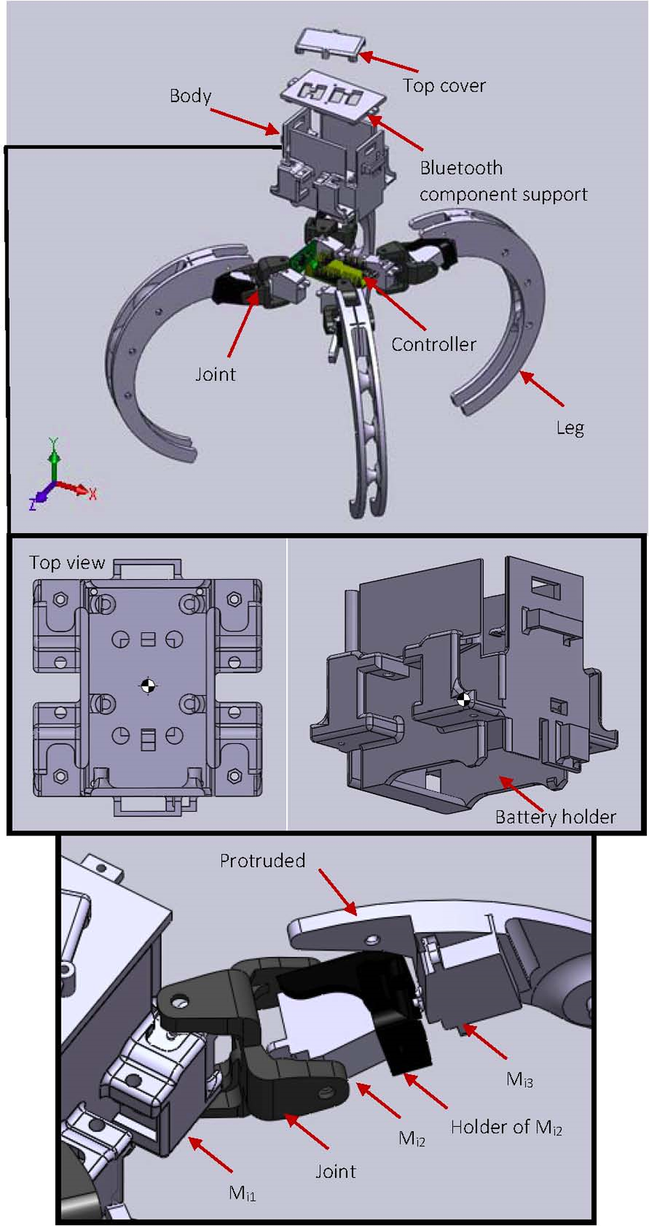
CAD models of Scorpio in exploded and local views.

Transformation from crawling to rolling in CAD models.

Prototype of Scorpio robot.
Kinematic modeling
In this subsection, the forward kinematic model of the robot is deduced based on the product of exponentials (POE) formula. 26 However, as far as we know, the POE formula was only applied to model the serial and parallel manipulators. Conventionally the kinematic models of legged robots (e.g. quadruped and hexapod robots) were established by the Denavit–Hartenberg (D-H) convention. Such an approach outperforms the D-H convention because kinematic parameters based on the POE formula vary smoothly with changes in joint axes, which guarantees that the error models are singularity free. 27 In addition, the error models are complete. Thus, we formalize the forward kinematics of the Scorpio robot based on the POE formula. Figure 6 displays the frame assignment and related parameters of a leg. A frame R located at the center of the robot body is assigned as the reference frame. Frame T is set as the foot frame where the contact with the ground happens.

Frames assignment of a single leg following the product of exponentials formula.
For the i th leg, given the joint variables θij (j=1,2,3), the corresponding exponential of a twist is

The forward kinematics map of a leg is

where

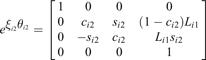

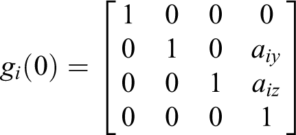
which is the initial configuration when θi = 0.
Expanding the terms in the POE equation (2) yields

where R(θi) is the orientation coordinate and P(θi) is the position coordinate.
Matrix gRSi transforms the coordinates from Frame S into Frame R, which is expressed as
Control system
For the purpose of efficient deployment and autonomous exploration, the Scorpio robot must be equipped with an efficient control system which consists of hardware and software components.
Hardware components
The installation of hardware devices inside or on the robot consists of the microcontroller, wireless communication component, mobility unit, interoceptive and exteroceptive sensors, and power unit. The specifications of the hardware components are listed in Table 2.
Specifications of the hardware used for Scorpio.
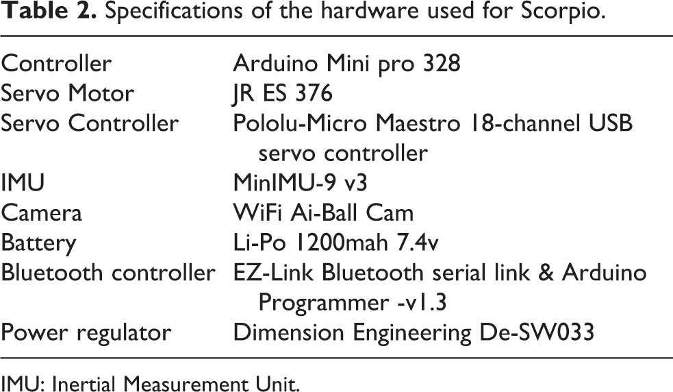
IMU: Inertial Measurement Unit.
Microcontroller
Arduino Pro Mini is chosen as the microcontroller. From Figure 7, we can see that Arduino Pro Mini is the central location to which interoceptive, communication, and mobility units are directly connected.
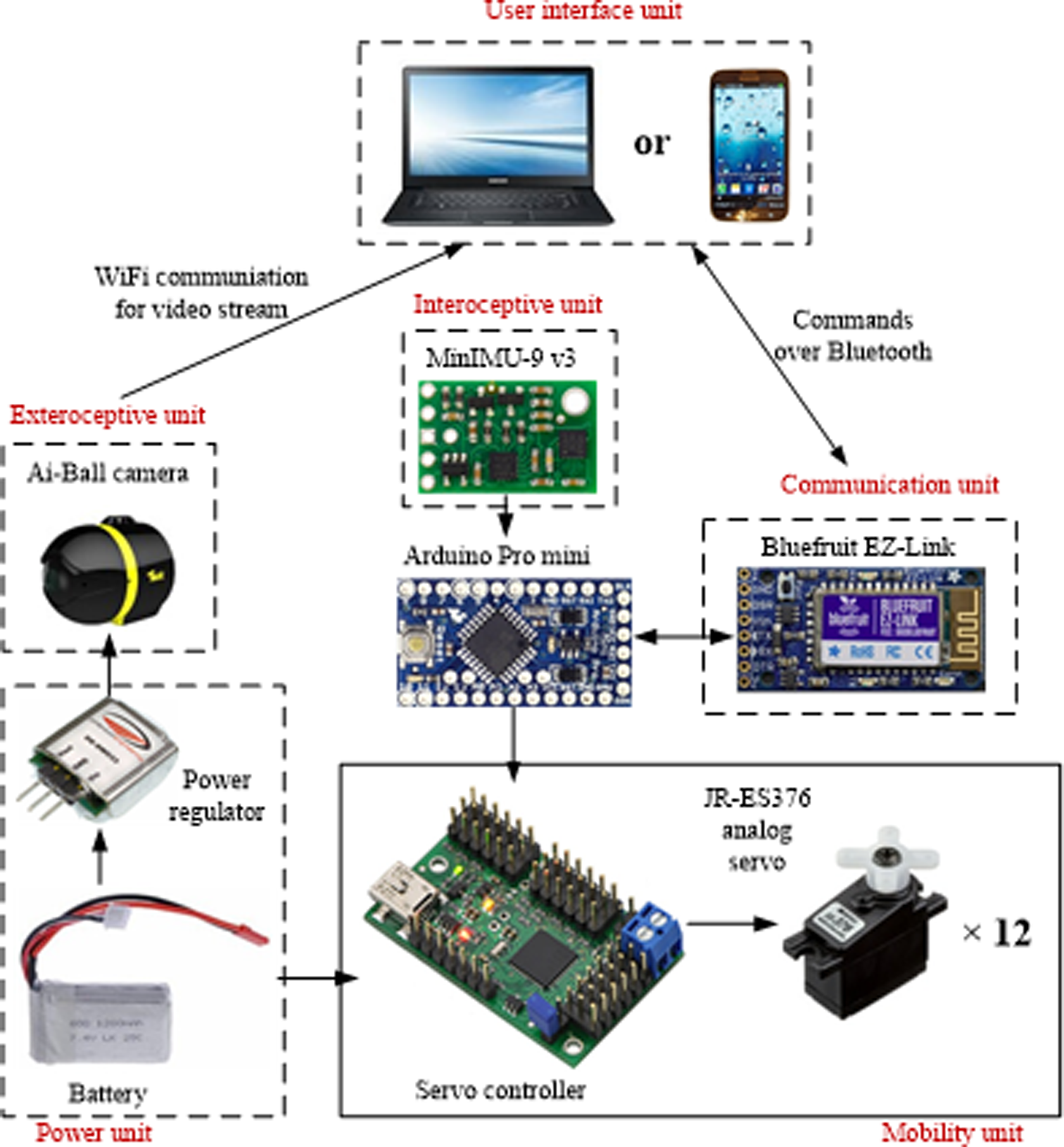
Hardware connection.
Communication
In our platform, the control mode of the robot could be teleoperation or automated. The communication between the host computer or handset and the robot is interfaced by a Bluetooth device (Adafruit Bluefruit EZ-Link). The device integrates the Bluetooth Serial Link and Arduino Programmer that has completely transparent Arduino re-programming and communication capability. Thus, in such a device, the commands communication and compiling are remote and wireless.
Joints/motors
Motion and transformation of the robot are realized by a set of 12 ES376 servo motors from JR Propo. The servo motor is ultra-compact (dimensions: 21.5 × 11.5 × 21.5 mm) weighing 11.5 g, which can only be used at 4.8V. The torque is 2.0 kg cm and the speed: is 0.16 s/60°. The schematic diagram in Figure 8 illustrates the locations of the 12 servo motors in the robot. The Pololu Maestro servo controller is used to drive the motors and interface the microcontroller and motors.

Schematic diagram of locations of servo motors and the reference frame of the IMU with roll, pitch, and yaw indicated.
Sensors
To be an autonomous system, the robot is expected to be equipped with a sensor suite. There are two kind of sensors, that is, camera and Inertial Measurement Unit (IMU), used in this platform for interoception and exteroception respectively. The vision unit is composed of one Ai-Ball camera. The camera is operated wirelessly through Wi-Fi with a 60° view angle. Even though the camera is small (30 mm in diameter and 35 mm in length) and light-weight (100 g), to adapt the camera to the miniature and reconfigurable features of the robot, the shell and battery of the camera are removed and it is directly connected to the central controller. The IMU used is Pololu MinIMU-9 v3, which packs an L3GD20H three-axis gyro, an LSM303D three-axis accelerometer, and a three-axis magnetometer onto a tiny board. An I 2 C interface accesses nine independent rotation, acceleration, and magnetic measurements that can be used to calculate the sensor’s absolute orientation. A voltage regulator and a level-shifting circuit are included in the MinIMU-9 v3 board to allow operation from 2.5 to 5.5 V. Figure 6 give the roll pitch, and yaw with respect to the reference frame of IMU.
Power supply
The power supply for the robotic system is from a Li-Po battery (1200mah 7.4 V) to which the servo controller is connected. The battery powers the camera through a power regulator (Dimension Engineering De-SW033) for the sake of the voltage discrepancy. The power consumption of six elementary components is tested in no-load condition respectively and showed in Figure 9. It can be seen that the servo motor and the Ai-Ball camera drain the most energy. And among others, the consumption value of the Bluetooth controller is the maximum, whereas the IMU sensor consumes the minimum energy. Comparing to these two components, Arduino Mini and Pololu controller are medium energy-consuming ones.
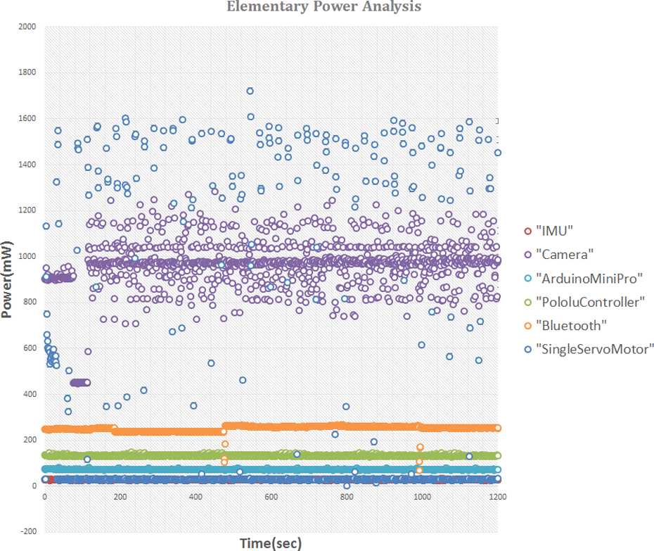
Power consumption of six elementary components in the robotic system.
Software system
In the current stage of the prototype, two kinds of user interfaces have been developed, which are Graphical User Interface (GUI) on a computer and an Android App on a handset.
The GUI (Figure 10) which is written in C # is for easy and efficient control and monitoring. A robot operator may use the control software to interact with the robot. The interface can display the original video and the one being processed. The buttons placed just below the original feed window facilitate to control a serial of actions, that is, crawling forward, backward, leftward, rightward, rolling, and recovering once falling down. The checkbox on the left-hand side is for the operator to choose the control modes. If it is unchecked, the robot is working in the teleoperation mode. The operator can send control commands like 1 for crawling, 2 for rolling, etc., through a serial communication port, for example, COM7 in this case. By checking the checkbox, the robot turns to autonomous mode based on vision without any human intervention. The remote desktop receives information from the robot and camera respectively. The right-hand panel displays the motion status of the robot and the possible terrain going through.

Software interface running in the host computer.
The Android App interface as shown in Figure 11 is created through MIT App Inventor 2. 28 The meanings of all the symbols of buttons are given in Table 3.

Android App interface running in the handset.
Functions of the buttons on the Android App interface.

Experiments
Gaits generation and transformation
Based on the mechanical design and architecture of the control system, Scorpio has sufficient DOF to complete a series of motions. The robot can crawl and roll using its legs through transformation of configurations, which is realized through controlling the rotations of servo motors. Table 4 indicates the actuated motors in different gaits. To crawl forward, backward, leftward, and rightward, the Mi1 and Mi2 of four legs are actuated. Figure 12 shows that the robot turns left and right in crawling mode.
Joints (servo motors) actuated in different gaits (the actuated ones are marked with ∗).


Turning left (a) and right (b) in crawling mode.
By changing the rotation angles of M33 and M43 additionally, legs 3 and 4 bend and form a circle shape like a wheel with legs 1 and 2, the robot can turn to the rolling mode from the crawling one. Figure 13 shows the full process of configuration transformation between crawling and rolling. It is observed that the configuration of Scorpio changes the gait from the crawling mode to the rolling mode, and then returns to the crawling mode. Figure 14 gives the flow chart of the generation of rolling locomotion and Figure 15 shows the measured roll and angle and roll angular velocity during performing rolling motion by IMU. The roll angular velocity is used to judge whether the legs need to actively assist the rolling or not. If the angular velocity is large enough (≥200°/s in this case), the legs are not actuated; otherwise the legs push the floor and cooperate to generate the rolling gait based on the detection of roll angles during the motion. In addition, the measured angles and angular velocities of roll, pitch, and yaw when rolling changes to crawling are shown in Figure 16.
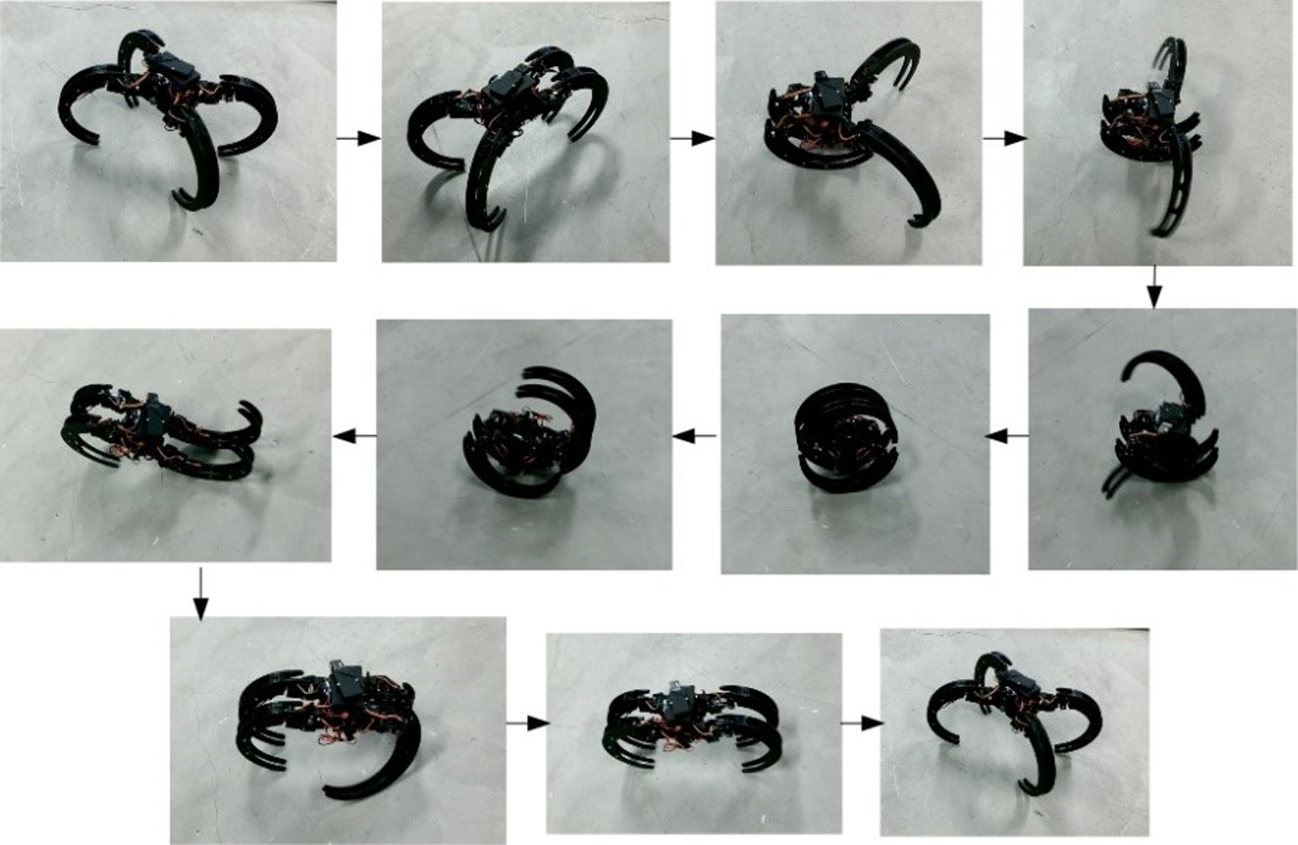
Transformation phases between crawling and rolling (crawling → rolling → crawling).

Flow chart of rolling gait generation of Scorpio robot.

Roll and roll angular velocity measured by IMU during rolling motion.

Angles and angular velocities measured by IMU when rolling changes to crawling.
Recovery
The rolling locomotion is efficient to move over smooth terrains. However, the rolling robot is prone to falling down when it is blocked by some obstacles, especially when the external force is coming from the side. Therefore the recoverability would be critical for practical applications. Once the robot falls down sideways when rolling, the IMU sensor feeds the roll and pitch information (shown in Figure 17) to the robot, and then the recovery mode is triggered and the robot is able to recover from the fallen state to the standing state. Figure 18 shows the typical scene of the sideways recovery. The robot first actuates the Mi2 joints on the two legs of a half circle and then stretches four legs. The two legs on the side near the ground push the robot body into its default state. In this process, all the motors are actuated to complete the action as indicated in Table 4.

Flow-chart of the whole control system including recovery by IMU and terrain-perception based reconfiguration algorithm by vision.
Sideways recovery of Scorpio.
The crawling gait may also suffer from falling down. For instance, the robot could be upside down in the case of falling down or being pushed down the steps. By activating the reconfigurability, the robot can also recover from the upside-down state to the standing state involving all joints. From Figure 19, it can be observed that the robot first rotates one pair of legs to the opposite pose. A leg of another pair rotates to the opposite orientation so as to push the robot into sideways state. Then the leg recovers to its original pose. Subsequently the robot stretches four legs and the two legs on the side near the ground push the robot body into its default state. Finally Scorpio stands up again thanks to the rotational ability of the joints of the four legs. Figure 20 shows the corresponding evolution of pitch and roll angles measured by IMU during sideways and upside-down recoveries respectively. It can be observed that the angles change from the prior state (fallen state) to the post state (standing state) smoothly.

Upside down recovery of Scorpio.

Pitch and roll angles measured by IMU during sideways and upside-down recoveries respectively.
The recovery capability increases the robustness and versatility of the robot in terms of navigability. Figure 21 shows a scenario ehere the Scorpio goes down the stairs with reconfiguration. The Scorpio first uses the rolling gait to move down the stairs and is tripped over after getting over first few stairs. Subsequently the robot stretches four legs and pushes the stairs to tumble down. Thus far, this operation has been conducted in manual mode.

Scorpio going down stairs by reconfiguration.
Terrain perception
IMU-based perception
Other than the robustness and versatility endowed by its reconfigurability, another merit is the adaptability to the different terrains that Scorpio can navigate. As per the terrain facing, the reconfigurability allows the robot to transform into the configuration that can better perform more efficient locomotion. Figure 22 shows a scenario where the Scorpio robot changes to the rolling gait when entering a slope from a horizontal surface. The logic behind this is that when the robot enters the slope, the IMU sensor detects the deviation of the roll angle beyond a certain threshold. The rolling mode is triggered and the robot transforms into the rolling gait. Then the robot can move down the slope by the gravitation and continue to move forward by the inertia. The rolling locomotion in this circumstance is much more efficient than the crawling one in terms of moving speed and consuming energy. Therefore the IMU sensor is used to detect the slope for changing to the rolling gait or not.

Scorpio going down the slope by reconfiguration.
Vision-based perception
Except for the interoceptive capability endowed by IMU, the exteroceptive capability for terrain perception can be realized by vision. The vision system is implemented on the Scorpio robot to recognize different types of terrains and configure itself accordingly. Due to the nature of this project, stability and scalability is required on this system. We implemented a multi-tier architecture for this vision system to ensure continuous operation by load balancing the vision and the robot locomotion and logic systems. The video stream is sent in real-time to the remote computer for vision processing and feedback. This reduces the critical on-board processing needed and the vision processing is not limited on-board but by the remote computer.
To showcase the vision-based terrain perception, the image processing algorithm we use is the color-based method which detects and segments a terrain from an image mainly depending on the significant color difference. Applying multiple region of interest (ROI) on the stream enables us to know where the terrain is from the robot’s vision. As shown in Figure 23, the ROIs defined here are three squares located on the bottom of the window (or the field-of-view of the camera).

Example of real-time image from the vision.
Simple terrain classification can be done by computing the average color space over a range of areas and comparing it with pre-defined classifications. The basic idea is that similar color space models could mean the same type of terrain. The steps of the algorithm are shown in Algorithm 24 and Figure 17. The video processing algorithm is basically getting the total average HSV (hue, saturation, and value) pixel values for each ROI. We calculate the average HSV values of all pixels in every ROI. The average HSV values for all the pixels in each ROI are obtained. Then every ROI has three values (the average hue, saturation, and value) finally. Figure 24 shows an example of the HSV of a pre-defined terrain and real-time video stream from robot’s vision and their parameters. Subsequently the three ROIs (nine values) are compared with the three pre-defined values. If the differences of the HSV values of any ROI are within the thresholds, the perceived terrain is considered to be the pre-defined terrain. The thresholds are determined by a trial-and-error method. In this case, they could be ±30 or ±40 which could be specified by the user.
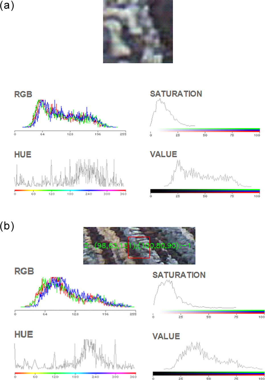
Pre-defined terrain type and real-time video stream from robot’s vision and their parameters: (a) example of pre-defined terrain; (b) real-time detected terrain.

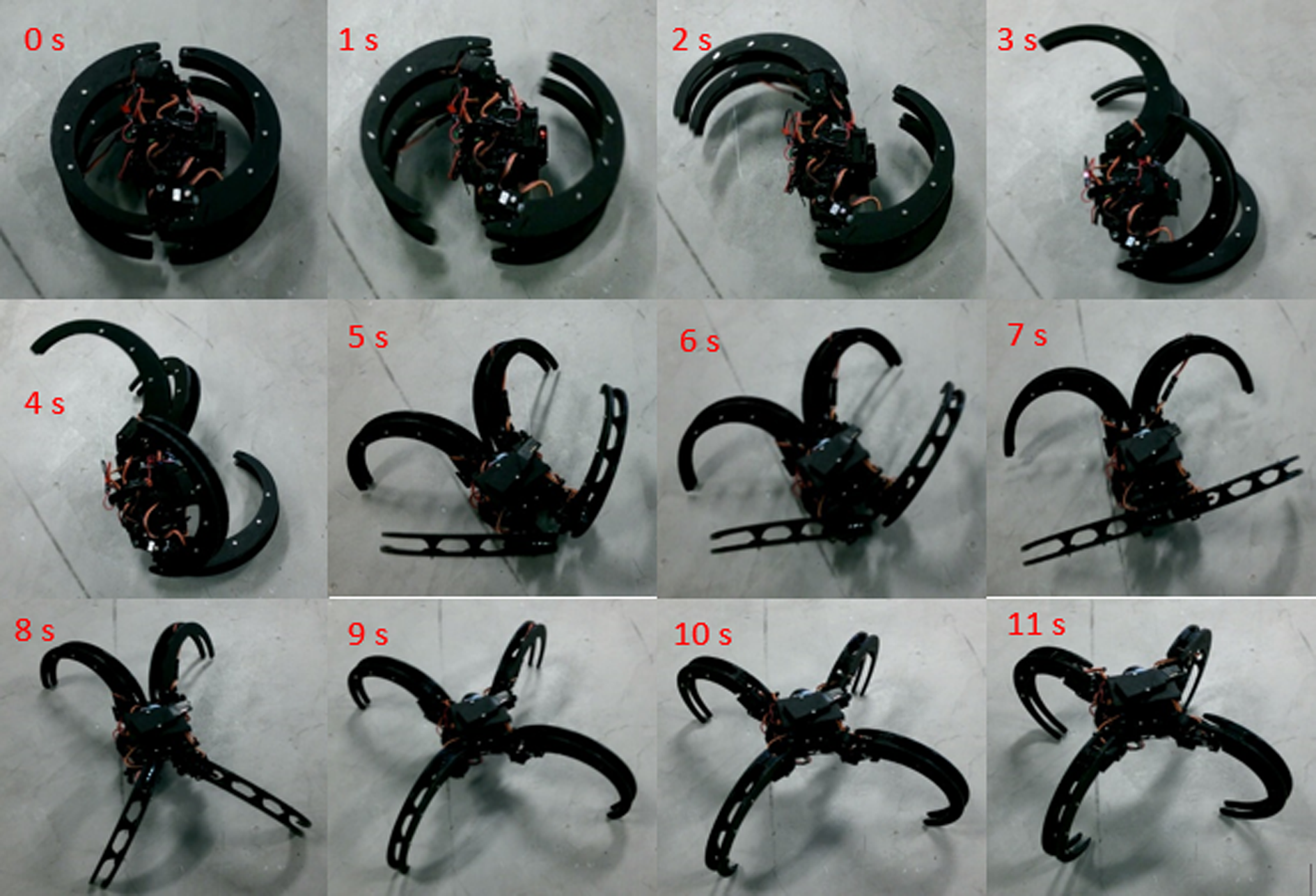
To showcase the primary adaptive reconfigurability of Scorpio, a simplified scenario is established for terrain perception by using black and white card boards on the floor. The reconfiguration gait generation based on the terrain perception is illustrated in Figure 25 where the top-left windows show the views of the on-board camera. Defining three squares on the bottom of the window, the robot decides to crawl if the white color is detected on the three squares at the same time. Conversely, once the three squares detect the black color at the same time (as Figure 25 at 5 s), the robot reconfigures to the rolling mode. The image processing algorithm is only working in relatively stable conditions, that is, in crawling gait. After a period of rolling (as shown in subfigures at 14t, 15, and 17 s), the robot recovers to the crawling state (at 22 and 28 s) and does terrain perception, and then makes the decision to continue crawling or turn to rolling.

Black and white terrain perception by on-board camera and reconfiguration gait generation based on the visual information.
Conclusions
In this paper, we reported on the design and performance testing of a novel legged reconfigurable robot named Scorpio. The robot is able to crawl and roll which is inspired by a Cebrennus rechenbergi spider found in deserts of Morocco. The robot is equipped with four reconfigurable legs capable of directly changing the morphology of its crawling mode into rolling mode, where the same set of actuators can be efficiently utilized in both modes without need of extra mechanisms. It follows that the robot can move as either a quadruped (crawling) or as a wheel (rolling mode). The mechanical design, control system, sensors, and software are described in detail.
The perceptual performance of the robot is experimentally validated. As expected, the robot is able to crawl, roll, and transform between the two states. On the interoceptive side, with IMU the robot can recover from sideways and upside-down falling states to the original standing state. On the exteroceptive side, thanks to the vision system, the robot is able to change its gaits through perceiving black and white terrains automatically.
The autonomous capabilities will be explored further in future work. For example, algorithms will be developed for perception and classification of different terrains (e.g. tile, carpet, and glass). The robotic system will be improved to autonomously navigate over the small bumps and down the stairs by using computer vision. Furthermore, the energy-aware behavior of Scorpio will be explored for the purpose of constructing an energy management system that maximizes the working efficiency in a given power limit.
Footnotes
Acknowledgements
This article is a revised and expanded version of a paper entitled “A bio-inspired reconfigurable robot” presented at the 3rd ASME/IFToMM International Conference on Reconfigurable Mechanisms and Robots (ReMAR 2015), Beijing, China, 20–22 July 2015.
Declaration of conflicting interests
The author(s) declared no potential conflicts of interest with respect to the research, authorship, and/or publication of this article.
Funding
The author(s) disclosed receipt of the following financial support for the research, authorship, and/or publication of this article: This work was fully supported by the Temasek Project (grant number IGDST1301018) at SUTD, Singapore.