
Abstract
This article presents a comprehensive survey of reconfigurable modular robots, which covers the origin, history, the state of the art, key technologies, challenges, and applications of reconfigurable modular robots. An elaborative classification of typical reconfigurable modular robots is proposed based on the characteristics of the modules and the reconfiguration mechanism. As the system characteristics of reconfigurable modular robots are mainly dependent on the functions of modules, the mechanical and electrical design features of modules of typical reconfigurable modular robots are discussed in detail. Furthermore, an in-depth comparison analysis is conducted, which encompasses discussions of module shape, module degrees of freedom, module attribute, connection mechanisms, interface autonomy, locomotion modes, and workspace. Meanwhile, many reconfigurable modular robot researches focus on the study of self-X capabilities (i.e. self-reconfiguration, self-assembly, self-adaption, etc.), which embodies autonomy performance of reconfigurable modular robots in certain extent. An evolutionary cobweb evaluation model is proposed in this article to evaluate the autonomy level of reconfigurable modular robots. Although various reconfigurable modular robots have been developed and some of them have been put into practical applications such as search and rescue missions, there still exist many open theoretical, technical, and practical challenges in this field. This work is hopefully to offer a reference for the further developments of reconfigurable modular robots.
Keywords
Introduction
The concepts of reconfiguration and transformation are not fresh. From the 72 morphologies of Monkey King in the famous Chinese classic fiction, “Pilgrimage to the West,” to the fashionable movie all around the world, “Transformer,” transformation brings people infinite imaginations and inspirations. Meanwhile, the notion of reconfiguration was understood from the perceptual knowledge to rational application undergoing a continuously developmental, extending, and enriched process. In recent years, applying the ability of reconfiguration to solve practical problems has attracted the interests of many researchers. With the demands of product diversity and economic globalization, the applications of reconfigurable systems have been first implemented in the advanced manufacturing industry. 1 The reconfigurable manufacturing system is flexible to new production paradigms. 2 Furthermore, the replaceable end effectors have been proposed to adapt to the different tasks in the field of industrial robots. 3 For some special exploration tasks, the demand of mobile operational robots was also gradually enhanced, with the expectations that the mobile robots can undertake more complex tasks. 4 Because the functions of conventional robots that are predetermined in a top-down form, from the highest level of abstraction to the lowest, 5 most of them are designed to accomplish certain specific tasks. As for some unpredictable circumstances, developing a kind of robots that can change their shapes and functions to adapt to the working condition is an important step to address these practical problems and needed urgently. 6
Employing modularization to realize the reconstruction of the function and structure, reconfigurable modular robot (RMR) is a breakthrough method that can get rid of the restriction of conventional fixed-configuration robots. The history of RMRs is first reviewed below.
The origin of RMRs can be traced back to 1950s, when John von Neumann 7 proposed a notion of the universal automata as a basic framework of reconfigurable robots. Although Neumann did not develop the physical prototypes, his theory has a far-reaching influence on the development of reconfigurable robots. Subsequently, Lionel Penrose 8 proposed the model of self-replication, which can form various structures during random shaking. Afterward, this area of research was almost forgotten. Until the late 1970s, with the development and wide applications of microelectronics, the passion for researching reconfigurable systems was started again. In the late 1980s, Toshio Fukuda and Seiya Nakagawa 9 proposed a novel reconfigurable robotic system “Dynamically Reconfigurable Robotic System (DRRS).” The DRRS consisting of many modules can reconfigure its own structure depending on the given task. On the basis of DRRS, Fukuda and Kawauchi 10 carried out substantial work on a robot system called cellular robotic system (CEBOT) and developed four versions of prototypes. Afterward, various types of RMR prototypes have been designed in accordance with the CEBOT. Researchers have proposed many innovative approaches to design their RMRs, promoting the study of RMRs to become one of the most prevailing research fields.
The most prominent features of RMRs are their adaptability, versatility, expansibility, and robustness. 11 RMRs can deliberately change their shapes by rearranging connectivity of their modules manually or autonomously to adapt to new circumstances or perform new missions. For example, they can transform into a snake-like shape to pass through a narrow pipe, reorganize as a spider-like robot to traverse the rough terrain, or form a rolling shape to move quickly over a flat ground. 6 When a fault occurs, the system can still maintain some operational capabilities as well as detect and solve problems quickly.
From the biological standpoint, the architecture and mechanisms behind the organisms are the intrinsic core to enable them to function. For an RMR, the characteristics of the system depend on the dexterity of modules. So, designing appropriate modules dominates the kernel position of the whole system. 11 Currently, the principles of standardization, serialization, and modularization are adopted in the design of these modules. And each module carries individual sensing, actuation, and control components, which is the base of realizing the reconfiguration of structure and function in module level. 12 Furthermore, inspired by biological morphologies, some researchers have developed some modules with excellent abilities of locomotion and manipulation and integrated with some advanced control algorithms (swarm intelligence, self-organization, etc.) which ensure that the system can obtain a good dynamic performance. 13
This survey aims to investigate the origin, history, the state of the art, key technologies, challenges, and applications of RMRs. The remainder of this article is organized as follows: The detailed classification of RMRs is presented in section “Classification,” based on the main attribute factors: the mobility of modules, the reconfiguration mechanism, the size of modules, the autonomy, the functions, and the architecture of topology. Section “State of the art of RMRs” discusses the features of some typical RMRs with a comparison of performances and characteristics, followed by the recommendation of a cobweb evaluation model of the autonomy level. Section “Key technologies and challenges” concludes key technologies and challenges in this field. Finally, several practical and potential applications are introduced in section “Applications and future directions,” and conclusions are provided in section “Conclusion.”
Classification
Modules are the basic elements of RMRs, so the function of modules will directly determine the capability of the whole system. Based on the independent mobile ability of modules, the RMRs can be broadly classified into two major categories: modular mobile robots and modular restructured robots. 14 Most modular mobile robots adopt independently driven wheels or tracks to propel the systems forward, ensuring that the system can obtain good security and stability. Furthermore, taking into account the reconfiguration mechanism, the category of modular mobile robots can be divided into two sub-categories: joint-motion robots and joint-reconfiguration robots. For the modular restructured robots, the compositional modules do not have the independent mobile ability, but have a high functional integration and can be rearranged into various configurations, so the whole systems have strong reconfiguration and locomotion abilities. Modular restructured robots can also be divided into two sub-categories: macro-sized reconfigurable manipulators and mini-sized reconfigurable or self-reconfigurable robots based on the size of modules, the autonomy of transformation, and the function of the system.2,11 Finally, these sub-categories can be further divided into serial pattern and parallel pattern, 2 chain architecture, lattice architecture, and hybrid architecture. 11 Figure 1 demonstrates an elaborative classification tree of the RMRs.

Classification tree of RMRs.
State of the art of RMRs
For different mission requirements and environment, different categories of RMRs have different design methodologies. A framework called MITE which emphasizes four basic aspects, that is, (1) module properties, (2) information perception and sharing, (3) task, and (4) environment, is proposed to characterize the design and application of RMRs. 15 As we know, RMRs are designed for specific tasks and various complicated environments, and the hardware design of modules is the core problem which directly dominates the whole system performance. In this section, we mainly focus on the hardware design characteristics of RMRs, the reconfiguration mechanism, the autonomy level, and the mission-based adaptability. According to the above classification tree, these platforms which belong to the same category or sub-category will be discussed together, and each category of RMRs will be analyzed and compared in detail in this section.
Modular mobile robots
Modular mobile robots are designed to carry out certain search and rescue missions in unstructured environments or extreme dangerous environments. An individual module should possess the independent ability to move or operate. There are three basic types of locomotion in the design of modules: (1) wheels and crawler tracks, (2) legs, and (3) articulated structures. 16 By virtue of the interfaces and connection mechanisms, modules can dock into a whole system, and dynamically adjust their postures in relation to each other to adapt to the rough terrain. This type of robot has excellent locomotion capabilities on rough terrain and obstacle. In this section, we will discuss the typical RMRs in two sub-categories: joint-motion robots and joint-reconfiguration robots.
Joint-motion robots
The joint-motion robots relate to a family of reconfigurable robots whose structural morphologies are changed by controlling joints for connecting two modules. When they are changing their configurations, the modules remain connected, that is, without disconnection, and the number of modules remains unchanged. Typical designs: novel unmanned ground vehicle (NUGV), 17 AMOEBA-I, 4 and El-Dorado-II 18 will be discussed in the following.
The unmanned ground vehicles (UGV) work as the supporting equipment in military field. They need to be designed into small size and lightweight. Besides, they should have a certain mobility and environmental adaptability. The NUGV 17 is a tracked vehicle which was designed in accordance with the requirements of the Army’s Future Combat Systems soldier UGV. The whole system has 6 degrees of freedom (DOFs) and is composed of three segments: a core module and two tracked mobile modules. The core module and the mobile module are connected by the 2-DOF revolute joints, guaranteeing the conversion of configurations. The structure of NUGA was developed symmetrically, so that it can perform the same flexibility in the forward and backward directions. The flexible 2-DOF joints provide the ranges of 0°–360° of rolling and 0°–180° of yawing. Furthermore, via the joints, NUGA can adjust the center of gravity to keep system balance when walking like a humanoid robot.
The chain-type RMR, AMOEBA-I, is also an integrated system, which owns the characteristics of manual reconfiguration and automatic reconfiguration. The whole system is composed of three mobile modules, two link arms, and two pairs of pitch and yaw revolute joints. 4 The main control unit, wireless control unit, and cameras are located on the top of the middle mobile module. An individual module can only execute the forward and backward movements without turning around. The offset link arms and revolute joints prevent the module from separating from the adjacent module. The change of configurations is realized by changing the relative positions of modules when controlling the revolute joints. The related research works by Liu et al.4,19–21 feature the configuration representation, 19 the configuration network, 20 the center configuration, 21 and configuration experiments. 4 The configuration matrix was proposed to represent the corresponding topology structure, and the isomorphic configurations can be easily differentiated by the configuration matrix. The configuration network consisted of nine kinds of nonisomorphic configurations was proposed in the research of reconfiguration route optimization. 20 A triangular formation was chosen as the center configuration considering the minimum energy consumption among the nine available configurations. 21 Furthermore, different configurations were analyzed for the adaptability to different terrain conditions. The configuration experiments have shown that the linear configuration (Figure 2(a)) can easily go through a narrow silt with the strong obstacle climbing ability; that the triangular configuration (Figure 2(b)) owns the excellent climbing ability and stability as observed in the testing on terrain of snow, grass, and debris; and that under the parallel configuration (Figure 2(c)), the robot consumes the least amount of energy and can perform various flexible movements such as turning on the spot.

Three different configurations of AMOEBA-I: (a) The linear configuration, (b) The triangle configuration, and (c) The parallel configuration (courtesy of State Key Laboratory of Robotics, Shenyang Institute of Automation, Chinese Academy of Sciences, China).
The reconfigurable rover, El-Dorado-II, is a parallel joint-motion robot for the purpose of probing the rims or insides of craters in exoplanet. 18 But the wheel slippage is a very critical problem to affect the traversing maneuvers of the rover, leading to that the rovers may be immobilized in the loose soil. El-Dorado-II has four-wheeled mobile modules supporting the main body. Each module has 2 DOFs: one is to adjust the length of the independent telescoping mechanism to control the posture of the rover and the other is to drive the wheel to move on the terrain. The slope experiment has proved that El-Dorado-II can provide a self-adaptive configuration to resist the longitudinal and lateral slippage.
Joint-reconfiguration robots
The joint-reconfiguration robots are another class of modular mobile robots, and their structural morphologies can be transformed by changing the number and connection methods of modules. Compared with the joint-motion robots, the disconnection of modules is available for the joint-reconfiguration robot with most modules equipped with detachable docking mechanisms, such as robotic manipulators, grippers, and couplings. The modules can be freely combined into some desired configurations to finish the specific assignment. In Tokyo Institute of Technology, Hirose coworkers22–25 have devised many joint-reconfiguration robots for the purpose of searching in hazardous environments, rescuing survivors trapped in collapsed buildings, and exploring in an alien planet. The typical designs include Gunryu, 22 Super-Mechano Colony (SMC), 23 Souki-II, 24 and Souryu series. 25
The group robot Gunryu is an articulated-body mobile robot 22 inspired by the new conception of using a passive manipulator as a connecting mechanism. The modules can form various configurations for the high adaptability and reliability. But the process of reconfiguration is completed manually resulting in a poor performance of controllability.
SMC is the most representative reconfigurable planetary rover, consisting of a mother rover and some detachable child rovers. 23 The child rover (Uni-Rover) is composed of a 4-DOF manipulator (3 DOFs for the arm and 1 DOF for the gripper) and a 1-DOF wheel, so that it can take both manipulation mode and locomotion mode. The mother rover cannot move independently without the Uni-Rovers that can work as the wheels to supply the motion. Here, the reconfiguration has twofold meanings: the reconfiguration between the mother rover and Uni-Rovers and the reconfiguration among Uni-Rovers. The design purpose of SMC is as follows: When the mother rover finds some interesting objects, it detaches some Uni-Rovers and let them form a new mobile robot. When Uni-Rovers complete the mission, they will dissolve and return to the mother rover to act as one of the wheels. The later generation of the model of the Uni-Rover, Souki-II, 24 follows the former structure of the arm-wheel hybrid robot, which can change its mode from the wheeled locomotion mode to the manipulation one. Compared with the Uni-Rover, Souki-II adopts a symmetrical configuration. And its arm is installed in the center of the wheel body, and the associated manipulator owns 5 DOFs (4 DOFs for the arm and 1 DOF for the gripper). Therefore, the Souki-II can move more smoothly and manipulate more flexibly. A single Souki-II module has a limited obstacle-traversed ability. But the cooperation of multiple Souki-II modules can perform an excellent mobility.
Souryu series robots were developed for the purpose of finding survivors trapped inside collapsed buildings. 25 The first version Souryu-I is not an RMR, because the three bodies is designed into a single entity and is driven by one motor by a power transmission axis. However, the 3-DOF joint mechanism (2 active DOFs for yawing and pitching motions; 1 passive DOF for rolling motion) is flexible to adapt to irregular terrain. The most outstanding feature between Souryu-II and Souryu-I is that Souryu-II can be detached into three bodies. But each body does not own independent motor, so Souryu-II is not an RMR. The third version of Souryu robot is composed of two standard tracks. Each body has an independent motor to drive two crawler tracks, so Souryu-III is a true RMR.
For improving the moving ability on terrain, Arai et al. 25 adopted a novel “metal-reinforced crawler track” with three features: lightweight, great strength, and low driving resistance. Two new track structures, independently actuated double-sided crawler and mono-tread crawler, have been applied to the models of Souryu-IV and Souryu-V, respectively. Furthermore, a compound grouser pattern combining a block-type grouser and a thin V-shaped grouser was applied to the track. This leads to that when the crawler track encounters an obstacle, the block-type grouser bends to allow the obstacle to go inside, and consequently, the thin V-shaped grouser grips the obstacle. Two different joint driving units have been developed for the two designs, respectively. The joint mechanism (2 active DOFs for yawing and pitching motions) of Souryu-IV is similar to those employed in Souryu-I, -II, and -III, and a blade spring has been arranged under the joint for generating the elastic rolling motion and absorbing shocks. As for Souryu-V, joint mechanisms can only be installed on its both sides. A new joint mechanism is composed of three elastic rods. Herein, rod shortening and lengthening mechanisms are utilized so that the yawing motion results from the lengthening of one elastic rod located in the upper area and the shortening of the other elastic rod, and the pitching motion results from the lengthening of one elastic rod located in lower area and the shortening of two elastic rods located in upper area, and the deflection of the elastic rods can generate the passive rolling motion and absorb shocks. Both Souryu-IV and Souryu-V have their own strengths and weaknesses, which should adapt themselves to two different practical purposes. Souryu-IV has a higher maneuverability and can turn around on the spot, but it is easy to get stuck on rubble. Souryu-V has a simpler structure, which can easily avoid getting stuck, but its controllability is not high.
Inspired by the new robotic concept originated from collective and reconfigurable robotics, the Swarm-bots (S-bots) system employed a tracked and wheeled mobile mode in the module design.26,27 For achieving multiple functions, each individual module is outfitted with nine motors: two motors for the mobile unit, one motor for the rotation of the upper part, and six motors for grasping and attitude control of the grasping mechanism. Equipped with the advanced sensor system (force sensor, proximity sensors, three-axis inclinometer, omnidirectional microphones, camera, etc.), consequently, each module can easily grasp and lift another module, perform autonomic movement and navigation, and communicate with others. Furthermore, multiple S-bots can form a reconfigurable distributed robotic system, which behaves a better environmental adaptability and interaction capability with tasks than a single module. 28 For example, such a reconfigurable system can cross a hole, transport an object, and navigate over unknown terrain.
The M3Express 29 system raised a concept of low-cost mobile RMRs. The main components of modules are made of low-cost plastic materials and actuators. Each module has an L-cylinder-shaped structure with three wheels, each of which can also serve as a docking interface and offer 1 revolute DOF. The genderless docking mechanism (the connection of pins and holes) is embedded into the inner of the wheel surfaces, and a sliding wedge mechanism drives the pins to insert the holes of the other module to finish the docking process. Herein, a spring installed between each pin and hole is used to disconnect two modules. Of the three wheels, two make the module as a differential-drive robot, and the third wheel is fixed orthogonally to the driving wheels for helping modules form complex configuration. However, this design arrangement will cause a large friction when the module is moving so that the omni-wheels are employed to reduce the friction force.
The Trimobot system 30 is also a hybrid modular mobile robot, which has a hexahedral structure with six docking interfaces (including an active mechanical hooking mechanism guided by an infrared (IR) sensor and five passive faces). Each module is equipped with a camera and a wireless communication unit to capture and share information. A total of three omnidirectional wheels can guarantee that the single module rotate in arbitrary angles with a zero radius, and the combined configuration has a flexible mobility. Each module has a pitch joint, which ensures the chain configuration can realize a crawl locomotion gait on the uneven surface.
Modular restructured robots
As for modular restructured robots, individual modules can perform rotation and linear motion. Through manual or automatic interfaces, the robots can form different topological configurations. This category has excellent capabilities on multi-tasking situations and unstructured environments. In this section, we will discuss the corresponding designs in two sub-categories: macro-sized reconfigurable manipulators and mini-sized reconfigurable or self-reconfigurable robots.
Macro-sized reconfigurable manipulators
Compared with the conventional fixed-structure manipulators, modular manipulators can have various configurations. The idea of modular design can improve the flexibility, scalability, maintainability, and interchangeability of systems, lending a good application prospect.
The first reconfigurable modular manipulator system 31 (RMMS) was developed at Carnegie Mellon University (CMU). This RMMS is composed of link modules and joint modules that are independent units with standard mechanical and electrical interfaces in function. RMMS can implement two restructured conceptions: the mechanical–structural reconfigurability and the software and hardware reconfigurability for the electrical control system. In addition, the interfaces are designed with the fast detached mechanisms and divided into the male and female interfaces, which ensures the simultaneous connection of mechanical and electrical systems. According to the task requirement, the robot configuration can be assembled manually, and the automatic recognition of configurations can be realized by the IR light emitting diodes (LEDs).
Furthermore, aiming at improving agility and flexibility in automated manufacturing systems, some theories and physical designs about modular reconfigurable robots (MRRs) were proposed by I-Ming Chen in Nanyang Technological University (NTU).32–35 Chen 34 also put forward the conception of reconfigurable robotic workcells, where three patterns of MRR systems with desired DOFs, (1) serial manipulator, (2) parallel manipulator, and (3) hybrid manipulator, can be rapidly assembled and configured by some kinds of standard modules (including rotary modules, linear modules, wrist modules, and gripper modules). As the number of potential configurations is larger, a configuration representation called the assembly incidence matrix is proposed to describe a specific configuration, and a framework for automating the models of kinematics and dynamics has been developed to facilitate the model-generation procedure for controlling the MRRs. 36 With the critical issue to find the optimal configuration to suit the given task, a method of master–slave agent architecture was proposed to solve this question. 35
Schunk Company (Germany) 37 is the most professional enterprise to design and produce universal reconfigurable modular manipulators, which is one of the most successful commercial RMR examples. The earlier PowerCube series contain three categories of modules: joint modules, link modules, and end-effector modules. These modules can be rearranged to form different configurations based on the task requirements. PowerCube series have been applied to many occasions. However, the external cabling may lead to the interference between wires and the robot body. Compared with PowerCube, lightweight arm (LWA) adopts the lightweight design principle with the new type motor to supply a greater driving torque. Therefore, LWA can get a higher weight–torque ratio. Moreover, the application of the harmonic reducer with a large center hole can carry out the inner cabling technology, which can avoid the interference in the operation process. LWA has a strong portability, which can be installed on a mobile platform as mobile manipulator. The latest generation Powerball LWA (4P) adopts the spherical modular design with 2 revolute DOFs, which can be assembled into a high-level compact system. The advanced control system is embedded in the joints to ensure the joints’ position, speed, and torque to be flexible and controllable. LWA 4P manipulators can be used for fixed or mobile occasions.
In brief, macro-sized reconfigurable manipulators have a strong practicality. Users can easily follow certain rules to assemble a manipulator that can meet their needs.
Mini-sized reconfigurable or self-reconfigurable robots
The research on mini-sized reconfigurable or self-reconfigurable robots is one of the hot and difficult topics in the international robotic field. Various shapes and functions of modules have been developed by researchers from different perspectives. Based on the autonomy of modules, reconfigurable robots and self-reconfigurable robots have been distinguished. Based on the topological characteristics, the robots were further classified into (1) chain type, (2) lattice type, and (3) hybrid type.
Chain type
For this sub-category of robots, modules are configured like a chain or a tree with many branches. The common configurations contain the snake-like configuration, the rolling-track configuration, quadruped robots, hexapod robots, and multi-legged robots. Typical chain robots include Polypod, 38 Conro, 39 PolyBot series,6,40 CKBot, 41 and so on.
The Polypod system 38 is the early basic model of the chain system where its cubic module owns 2 revolute DOFs, and the manual connection plates possess two functions: mechanical connection and electrical connection. This system manifests an excellent locomotion ability with multiple gaits, such as slinky mode, caterpillar mode, rolling-track mode, and multi-legged mode.
The Conro system 39 is a typical chain-type robot developed by Shen et al, which is composed of homogeneous modules. Each module consists of three parts and can perform pitching motion and yawing motion. The associated interfaces are divided into the active interface (with holes) and the passive interface (with pins). When the pins are inserted into the holes, switching on the shape memory alloy (SMA) triggered mechanism in the active interface can firm the connection. Each module is also a complete functional element, carrying a central processing unit (CPU), two motors, two batteries, and four pairs of IR sensors for communication and docking guidance, which enables modules to be assembled into various configurations such as a hexapod configuration. As a result of the motion control being the key research content to the Conro system, a centralized master–slave approach has been applied to control the robot. For this approach, the configuration should be identified beforehand where a directed graph representation of configurations has been proposed to describe the topology of the robot.
To further verify the autonomy of the design, the robot can be viewed as a dynamic network composed of nodes (denoting modules), in which the messages is routed from the source to the address of each node. The realization of dynamically changing topology requires to continuously plan the address and the route. A hormone-inspired adaptive communication and distributed control 42 was proposed to accomplish the desired shape changing and locomotion. The changes of the local topological network can be monitored via the hormone-inspired adaptive communication protocol, and the hormone-inspired distributed control can collaborate and synthesize the modules’ motion.
PolyBot series6,40 and CKBot 41 by Yim et al. are also chain-type RMRs. PolyBot generations 2 (G2) and 3 (G3) were created at Palo Alto Research Center. Unlike Conro whose interfaces are divided into female interfaces and male interfaces, PolyBot G2 modules adopt genderless interfaces. The grooved pin and hole connection mechanisms are driven via the SMA latch, and an IR ranging system can guide the closed-loop docking. So, the system can easily perform self-reconfigurations. For example, it can perform the transformation of three configurations: first from a rolling shape to a snake shape and then to a quadruped robot. Compared with G2, G3 owns a compact dimension of roughly 50 × 50 × 50 mm3 with a harmonic gear being used to increase the load carrying capacity.
The CKBot system was developed to verify the self-reassembly behavior for RMRs. 41 It is composed of three modular clusters. Each modular cluster has four modules and 4 DOFs, and the cluster carries a camera unit, controller unit, actuator unit, IR sensor unit, three-axis accelerometer unit, and electromagnetic interfaces. A scenario can be seen in Yim et al. 41 that under the action of an unpredicted event, the system was forced to explode into three parts and randomly scattered on the ground. First, each modular cluster erected the camera module to detect neighbor clusters and calculate the distance and orientation. Second, two modular clusters moved together and connected into a coherent entity which can share the common information via IR sensors. Finally, the group of two modular clusters continued to search the third cluster and followed the prior connection process to assemble into the former configuration. Other chain-type systems have been designed for different functions and objectives. The Molecubes system was developed to perform the self-reproducing behavior. 43 The Molecubes module is the standard cubic structure with 1 revolute DOF and two electromagnetic interfaces. The module only has an angular sensor to calculate the angle of the motor. The authors have proposed an evolutionary fitness-based algorithm to control the actions of docking, rotating, and detaching to accomplish the self-reproducing process of configurations, but modules need to be provided constantly. The design of ModRED robot 44 was to improve the intelligent technologies of planetary exploration, such as the self-organized ability in unknown environments. The ModRED module has 4 DOFs (3 revolute DOFs and 1 translational DOF), and the whole body can be divided into five cabins: three middle cabins including the control unit, battery unit, and actuator unit, and two lateral cabins equipped with the rotary-plate genderless single-sided docking interfaces. The module system offers a high level of intelligence. A fuzzy logic controller has been developed to dynamically adjust current motion of each module, which can guarantee the operability of modules. To verify this system, a special scenario where a set of modules were scattered on the ground with the communication range of each other was devised with the objective that the modules can search out and alliance with the nearby modules rapidly. A searching method of modeling the scenario as graph-based coalition formation problem has been proposed to find and form optimal coalition structures.
Lattice type
For lattice-typed RMRs, the robots can be configured into the connected or filled shapes in two-dimensional (2D) or three-dimensional (3D) space such as the crystal format systems. Compared with the chain-type RMR, the research on lattice systems is relatively abundant. Typical robots include Metamorphic, 45 Crystalline, 46 Prog.parts, 47 Miche, 48 ATRON, 49 Odin, 50 M-Blocks, 51 distributed flight array (DFA), 52 and so on.
The Metamorphic robot 45 is an early 2D lattice system, and its each module consists of six links with equal length to form a hexagonal shape. All the modules are equipped with electromechanical connectors and coupling mechanism which are actuated by DC motors. Each flexible joint can enable the module to roll around the adjacent module to form different shapes. The Molecule robot 53 is a 3D lattice robot. Its each module consists of two units and a rigid connection and has 2 DOFs and five interfaces. The gripper-type connection mechanism has been used to guarantee modules to form various configurations. The Telecube system 54 is another typical 3D lattice-type robot. Its modules have a cubic structure which can expand each side to accomplish motion along the lattice. Docking attachment was accomplished by means of permanent switching magnet faces. The communication unit and IR sensors can read the information of other modules and measure the extension of each surface of the cube to decide whether or not to connect with the adjacent modules. I-Cubes 55 modules consist of two distinct elements: the active link and the passive cube. The active link is a 3-DOF manipulator that is capable of attaching or detaching from or to the passive cube. A twist-and-lock attachment mechanism has been developed to provide a statically and dynamically stable system where modules can easily switch to unlocked position. The system can perform many difficult locomotion tasks, such as climb stairs, go through the pipe, and traverse the barrier.
Inspired by the biological muscle contractibility, 46 the Crystalline module was designed into a 3D cubic structure with four interfaces, two active interfaces, and two passive interfaces. The mechanical latch is adopted to connect two modules. As the muscle contraction movement, the Crystalline module has 1 DOF which can perform the expansion and contraction movement by driving the inner rack-and-pinion mechanism of four interfaces. The size of expansion is twice bigger than that of contraction. To achieve the whole locomotion, a controller for shape metamorphosis has been applied to control the expansion and contraction movement of modules.
For exploring the autonomy of RMRs, two robots, the programmable parts 47 (Prog.parts) and Miche, 48 were developed to verify the self-assembly and self-disassembly behaviors, respectively. The Prog.parts modules are the 2D triangular structures. Each module is equipped with three movable magnetic interfaces and an IR communication system. To verify the self-assembly behavior, the modules were scattered on the air-floating bed randomly under the disturbance of air. When they collide, they can choose to gather or detach. Furthermore, a grammatical approach similar to the chemical kinetics was proposed to regulate and optimize modules’ interactions so that the modules can be assembled into any desired configurations. In contrast with Prog.parts, Miche was developed to accomplish the self-disassembly behavior. The Miche module is the 3D cubic structures with three electromagnetic interfaces and a point-to-point IR communication system. The shells of modules were directly packed by printed circuit boards. Similar to the art of carving, the Miche system can configure any crystalline structural system as detailed below. At first, many modules were assembled into a standard cube with a certain volume, where each module can communicate with others freely. A disassembly algorithm was proposed to map the assembled model into a virtual model in the MATLAB software and then the desired configuration was delivered to the virtual model. The MATLAB sent commands to the controller of each module to alter each electromagnetic switch, and modules would fall freely under the gravity. Finally, the Miche system was disassembled into the target configuration.
The ATRON module 49 is composed of two hemispheres connected by a revolute joint. Each hemisphere has four interfaces (two male and two female interfaces). The male interface owns a mechanical hook which can match with the female interface. The structural stiffness of the interfaces and the motor power can enable many modules to assemble into an integrated configuration. As for the ATRON system, the main researches focused on the algorithms. For example, an online pattern generation algorithms can realize the self-reconfiguration, an anatomy-based algorithm can generate autonomous mobility patterns for the full assembly, and a distributed reinforcement learning strategy can achieve the adaptive locomotion. 56
The truss-based RMRs formed by link-and-joint structures are another kind of lattice RMRs. The Odin system 50 is the typical truss-based RMR which is composed of three heterogeneous modules, namely, the cubic closed-packed (CCP) joint module, the black telescoping link module, and the white rigid passive link module. Each CCP module includes 1 controller and 12 connectors. The ball-and-socket connection mechanism is adopted to provide some flexibility for joints. The telescoping links can control their length, but rigid passive links retain their length. The three modules can be assembled into the link-and-joint structure manually and can share power source. Considering the high stability and high strength of the triangular structure, the Odin system has adopted the triangular structure as the fundamental structure. And its most outstanding feature is the extensibility. When the whole system is subjected to external forces, the structural passive transformation can adapt the external forces, and the flexible joints can accomplish the active transformation to regulate the internal force distribution for the structure. Similar to the Odin robot, Morpho 57 is developed to explore the self-deformation behavior, which is composed of four modular components (active links, passive links, surface membranes, and interfacing cubes). By controlling the expanded and contracted action of active links, a deformable surface was built to exhibit the ability of delivering an object. Another similar truss-based RMR, amorphous modular robot, 58 has a quadrilateral structure, which consists of four links and four sphere joints. Each link has two linear actuators, which can drive the 2D configuration to achieve effective locomotion.
In addition, other novel lattice-type systems have been designed for different purposes. The M-Blocks 51 and 3D M-Blocks 59 are the most interesting lattice-type RMRs. Both of them have the similar appearances, the standard 3D cubic structures without any external actuated moving parts. The key innovation of M-Blocks is its new motion model, the momentum-driven module, where a flywheel and a brake are installed inside the body. By quickly decelerating the accumulated angular momentum, an impulse of torque can be created to realize 1 DOF rotating motion relative to the adjacent modules. Another important aspect in the design of modules is the docking interface, where the modules are connected by their permanent magnets embedded into their edges and faces. A total of 24 diametrically polarized cylindrical magnets are fixed coaxially on the 12 edges of the module frame, where two magnets are set back from the corner in each edge to guarantee that each module is free to rotate around their edge. In fact, the magnetic edges are working as the rotating hinges between adjacent modules and also serving to connect modules. To solve the misalignment problem, eight disk magnets are fixed on each of six faces in an eight-way symmetric pattern to guide the module into alignment after it finishes a rotating motion. However, the impulse of torque is random, which will lead to failure of the module movement. The M-Blocks module has only 1 revolute DOF, that is, it can rotate in 2D space. In contrast, the 3D M-Blocks has an enhanced ability of motion, which can rotate about three orthogonal axes in lattice-based locomotion. This outstanding characteristic owes to the new mechanical design, a plane-changing mechanism. This changing mechanism is fixed inside its module, and it has three contact points to maintain stability between two assemblies. Of these points, two are formed by bearings attaching the plane-changing mechanism to the module through its longest diagonal axis (the axis aligned between two opposing corners), and the third point has a retractable pin which is controlled by a SMA to fasten the changing mechanism. When the actuator of the changing mechanism is rotating around the diagonal axis at 120°, the flywheel can change its orientation to align with one of the coordinate axes. Furthermore, the flywheel can produce three directions of angular momentum which can allow the module to rotate in 3 DOFs.
A self-soldering RMR, named Soldercubes, 60 was developed to achieve the purpose of lightweight, low cost, and manufacturability in module design. Each module has 1 revolute DOF and six docking faces. Its most remarkable feature is the self-soldering connector where eight resistors can heat up the low-melting point alloy to realize the connection and disconnection between two modules. This docking mechanism can facilitate modules to form a lattice-based configuration with high-strength connections.
Most RMRs are working on the ground. The DFA is a reconfigurable modular multi-propeller vehicle. 52 Each DFA module has a hexagon shape, which is composed of three major components (a base frame, a top frame, and standoffs). The base frame is used to support the main loads including the motors, battery, sensors, and so on. The top frame is used to protect the external structure and the inner devices. The standoffs are used to connect and support two frames. Each module has a flying DOF and six electromechanical docking interfaces, where four permanent magnets are embedded in the standoffs to guide the docking process. The DFA system manifests the benefits of the cooperation ability of RMRs. Because a single flight module has a bad maneuverability, the combined configurations controlled by a distributed average consensus algorithm 61 can guarantee a desired stability and maneuverability.
Hybrid type
For hybrid RMRs, each module has several DOFs and interfaces enabling to form the chain architecture and the lattice architecture. So, this sub-category can perform a high level of transformation or locomotion. We will present some typical hybrid RMRs in the following paragraphs.
The most representative hybrid systems are the modular transformer (M-TRAN) series including three generations: M-TRAN I, 62 M-TRAN II, 63 and M-TRAN III. 64 These three generations were developed with the similar structure which is composed of two semi-cylindrical boxes (one active box and one passive box) and a connecting linkage. Each module has two revolute DOFs and six connection surfaces (three active interfaces and three passive interfaces). For the first generation, M-TRAN I, each module can only accomplish the movement and connection. The second generation, M-TRAN II, added some units such as the proximity sensor, acceleration sensor, and wireless communication equipment. On the basis of M-TRAN I and II, a local communication unit was added to M-TRAN III. The connection mechanisms of M-TRAN I and II employ the permanent magnet and SMA actuator. However, M-TRAN III adopted a mechanical latch (a hooking mechanism in the active module and clutches at the passive module), which performs a better performance on the speed and reliability of connection. The researchers have concentrated on the control strategies to acquire the optimal movement performance. M-TRAN I adopted a host computer control method to accomplish the self-reconfiguration; M-TRAN II used two methods: synchronous control and central pattern generator (CPG) motion control to acquire the optimal locomotion gait; M-TRAN III employed a synchronous or asynchronous distributed control method to ensure an adaptive motion of joints. In brief, M-TRAN III has the superior transformation and movement abilities, and it can easily perform a transformation process from a quadruped robot to a snake-like robot.
The SuperBot system 65 is also a powerful hybrid RMR. The purpose of developing the SuperBot robot was for the complex missions in the outer surface of the planet, requiring multiple locomotion modes. Each module consists of three units: two lateral actuator units and a medial revolute joint, which are assembled into a universal-joint-like mechanism with 3 DOFs in the ranges of 180° yaw, 180° pitch, and 270° roll. So, the system can perform many flexible motion modes, such as the parallel rolling locomotion on the flat ground and the creeping locomotion on the slope terrain. The control strategies follow the previous hormone-inspired distributed control for the Corno system. Two novel methods, table-based control and phase automata, have been developed for fast prototyping and coordinating module activities, respectively.
The UBot system 66 has two kinds of modules: active modules in black and passive modules in white. Each module is composed of two parts which form a cubic structure with 2 revolute DOFs and four connecting surfaces. Compared with other RMRs, UBot modules adopted hybrid connection mechanisms, where a hook-type connection mechanism was proposed to guarantee the stability of the connection, and another permanent magnet connection mechanism was developed for the preposition before the connection. A right angle shaft design was proposed to connect two parts and solve the problem of the cable wrapping. A host computer was used to simulate and control the robot to complete the multiple locomotion configurations, such as the snake-like configuration, the quadruped-walker configuration, and the loop configuration. Furthermore, a sinusoidal oscillator was employed as the joint controller to achieve the corresponding gaits. 67
The Roombots project provided a concept of the furniture-shaped structures, 68 which one can build any desired furniture with the homogeneous modules. Each module is composed of two sphere-like parts which are assembled into a roughly cubic structure with three revolute joints (one inner joint and two outer joints). An active connection mechanism can ensure that its four latching fingers can grab synchronously into the match module. The powerful DC motors equipped with high gear ratio gearboxes (about 360:1) can deliver sufficient torque to next module. The modules were attracted and guided by a virtual force-field, which are used to broadcast signals, check the collisions, and evaluate their near environment of their seeding positions. Thus, the modules can configure into multiple structures and perform different locomotion modes. A CPG as the motion controller working with an optimization algorithm was applied to optimize the locomotion gaits. A self-configuration algorithm was proposed to build a larger variety of furniture shapes.
For some new class of hybrid RMRs, their modules were designed with a certain mobile ability. However, the research on them is focusing on the capability of self-reconfiguration and self-assembly; so, we classify this robot to the mini-sized self-reconfigurable robot. The typical platforms include Sambot, 69 Scout, 70 SMORES, 71 and CoSMO. 72
The Sambot 69 is a multi-robot system which synthesizes the advantages of self-reconfigurable robots, self-assembly robots, and mobile robots. Its module has a cubic shape where the structure of Sambot can be divided into two parts: the active docking panel and the movable body with two driver wheels. The docking panel can rotate around the center axis of the movable body in a range of ±150°. The structure of Sambot is equivalent to a two-link module with 1 DOF. The front, back, left, and right faces of the mobile body are the passive docking interfaces. The connection mechanism adopted the autonomous docking hooks which were installed on the active docking interfaces, and several parts of docking grooves were designed in the passive docking interfaces. Under the guidance of the docking IR sensors, the docking hooks can easily insert into the docking grooves within a certain range of deviation. By virtue of the function of autonomous docking, the Sambot system can automatically form multiple configurations such as a snake-like configuration, a loop configuration, and a multi-legged configuration. Furthermore, a fuzzy controller is applied in the module to improve efficiency of the self-assembly process. 73
The Scout robot 70 is aiming at bridging a gap between swarm robots and self-reconfigurable robots. The single module has a track walking mechanism, which can enable the module with a swift locomotion on a flat terrain. Its module has a compact quasi-cubic shape with 2 DOFs (1 rotating DOF in the ranges of ±180° and 1 bending DOF in the ranges of ±90°) for reconfiguration and macro-locomotion of assembled configurations. Each module has two active docking faces and two passive docking faces where the docking mechanism also adopts the genderless interface. As its name suggests, the Scout robot was developed to explore the unstructured environment. For capturing the environmental information to the maximum extent, different kinds of sensors are incorporated into the design of modules, including humidity or temperature measurement, image capturing, laser scanning, 3D acceleration, localization, angle measurement, voltage, and current monitoring. In particular, a triangulation-based laser-camera sensor guarantees that the Scout robot owns a far-range sensing ability from 75 to 600 mm. By virtue of the sensors and locomotion capabilities, modules can easily explore the environment and interact with other modules.
The SMORES 71 system was developed toward a universal modular robot with the explicit goals in the design of system, module, and docking. Specifically, the overall goal of the SMORES system is changing shapes without human assistance and expensive cost, and two sub-goals are that the module can make the best use of resources and that the docking mechanism should be fast and power efficient. The SMORES module has a cubic shape with 1 pitch DOF (in the ranges of ±90°) and 3 revolute DOFs (no angular limits). And each module has one passive interface and three predominantly active interfaces. A docking key mechanism is used to drive the active interfaces to dock with neighboring modules with a high connection strength. Meanwhile, each interface has four hollow permanent magnets that can guide the docking action. In addition, 2 of 3 revolute DOFs at both sides of circular docking faces can work as the driving wheels to achieve the self-assembly mission; and the total 4 DOFs guarantee the SMORES to have a strong ability of self-reconfiguration.
The CoSMO 72 system is also a hybrid-type RMR with modules having mobile capability. Its module has a cubic structure with two L-shaped halves, where each half has a revolute DOF (in a range of ±90°). Each module has four docking interfaces, each of which adopts a mechanical hook to connect two modules. Two Archimedes screws are installed on both the left side and right side of the bottom to realize 2D locomotion. When both screws are rotating in the same directions, the module will move in a straight line. When both screws are rotating in the opposite directions, the module will move sideways. When one screw is rotating and the other is fixed, the module will turn direction. The dual-core analog-digital signal processor and full-duplex Ethernet network guarantee a high-speed computation and communication capability. A remarkable innovation is its energy-sharing function which allows to transfer energy between two modules.
Comparison analysis
To further illustrate the corresponding classifications and critical characteristics of these RMRs mentioned above, a comprehensive comparison analysis, including module shape, module DOFs, module attribute, connection mechanisms, interface autonomy, locomotion modes, and workspace, is listed in Table 1 (corresponding notation and explanations being described at the bottom of Table 1). Furthermore, a comparative analysis of advantages and weaknesses of RMRs which have been classified in different categories as mentioned earlier is summarized in Table 2.
Comparison of RMRs.

RMR: reconfigurable modular robot; DOF: degree of freedom; NUGV: novel unmanned ground vehicle; RMMS: reconfigurable modular manipulator system; NTU: Nanyang Technological University; DFA: distributed flight array; SMA: shape memory alloy.
Principle of classification.
Numbers denote the following module (joint module) shape: 1: cube; 2: cylinder; 3: cylindroid; 4: cuboid; 5: trapezium; 6: sphere; 7: hexagon; 8: triangle; 9: two connected semicylinder; 10: double cylindroid; 11: truss.
Number of DOFs mainly consider the degree of freedom performed by the module.
Numbers denote the following module motion attribute: 0: none; 1: mobile; 2: rotation; 3: translation; 4: manipulation; 5: fly.
Numbers denote the following module interface mechanism: 1: motionless mechanical connector; 2: link joints; 3: link arm and joints; 4: robotic gripper; 5: robotic manipulator; 6: SMA actuated mechanical latch; 7: electromagnet; 8: rotary-plate genderless single-sided docking mechanism; 9: electromechanical connector; 10: mechanical latch; 11: mechanical hook; 12: permanent magnet; 13: magnetic latch; 14: ball-and-socket mechanism; 15: rotary latching connector; 16: blade–spring joint mechanism; 17: elastic-rod joint mechanism; 18: parallel drive coupler mechanism; 19: parallel drive gripper mechanism; 20: concentric multilink spherical joint; 21: strong velcros; 22: self-soldering connector.
Numbers denote the following automatic level: 0: manual attaching or detaching; 1: manual attaching and autonomous detaching; 2: autonomous attaching or detaching.
Numbers denote the following locomotion modes: 1: track; 2: wheel; 3: roll; 4: snake; 5: creep; 6: biped; 7: multi-leg; 8: planar rotary; 9: spatial contractions and expansions; 10: topological deformation; 11: fixed operation; 12: float; 13: fly.
2D for two-dimensional space and 3D for three-dimensional space.
Comparison analysis of advantages and weaknesses of RMRs.
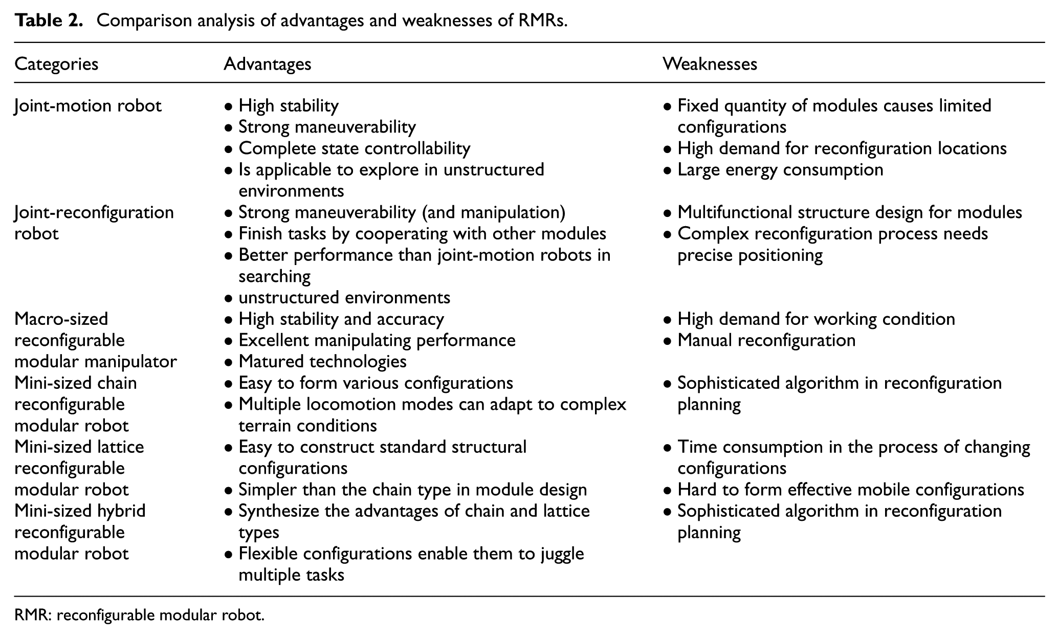
RMR: reconfigurable modular robot.
Autonomy evaluation
Autonomy is a significant ability of RMRs. It means that robots can make its own decisions and accomplish the scheduled tasks without external intervention. 85 Autonomy is also an important performance indicator for RMRs. Some emerging robots have demonstrated their self-X capabilities including self-reconfiguration,4,17,23,24,39,40,44,46,49,55,64,68,69,70–72 self-assembly,28–30,44,47,69,70–72,80–82 self-adaptation,4,17,18,22,25,50,57,58 self-organization, 28 self-disassembly, 48 self-reassembly, 41 self-reproducing, 43 and self-soldering, 60 which are embodiments of the autonomy. Different tasks have different autonomy requirements for the system, and the level of autonomy will decide whether the robot is suitable for uncertainty tasks. Therefore, there is a necessity for the evaluation of autonomy in RMRs. A cobweb evaluation model of autonomy was proposed by Wang and Liu 86 to assess the autonomy of unmanned systems. The principle of the evaluation model is ruled in that the cobweb evaluation model has an original point with several radiating axis, and each axis represents an evaluation reference aspect, which is an important index to determine the autonomy of the system. Each aspect has several grades, and these grades indicate technology maturity. For unmanned systems, connecting the adjacent axis’ rank scale can constitute the cobweb latitude, which can evaluate the system’s autonomy.
Furthermore, an evolutionary approach of the cobweb evaluation model is proposed for RMRs. The new method rules that the range of autonomy level is 0–10. Equation (1) can offer the result of the autonomy level for each RMR

Actually, the realization of the autonomy of RMRs is based on their hardware design, so the system hardware performance characteristics are chosen as the evaluation aspects including the module DOF, the module attribute, the interface autonomy, the locomotion mode, and the workspace type. The quantitative evaluation of autonomy level depends on the selected five aspects ranking in the order of the module DOF, the module attribute, the interface autonomy, the locomotion mode, and the workspace type, which are divided equally in a clockwise circle direction in the cobweb area. The grade description is defined as follows: The module DOF can be classified into six grades (0–6); the module attribute is classified into five grades (0–5); the interface autonomy can be classified into two grades (0–2); the locomotion mode can be denoted in six grades (0–6), which denote the numbers of robots’ locomotion modes; the workspace types are classified into two grades (0–2); the quantitative evaluation of autonomy level can be expressed as equation (2). The evolutionary cobweb evaluation model of autonomy level for the SMC-Uni-Rover is shown in Figure 3. The corresponding evaluation results of the autonomy level for the typical RMRs in Table 1 are illustrated in Figure 4.

where MDOF is the grade of module DOFs, Matt is the grade of module attribute, I is the grade of interface autonomy, L is the grade of locomotion modes, W is the grade of workspace, and St is the whole envelop area of the cobweb.

Evolutionary cobweb evaluation model of autonomy level for the SMC-Uni-Rover system.
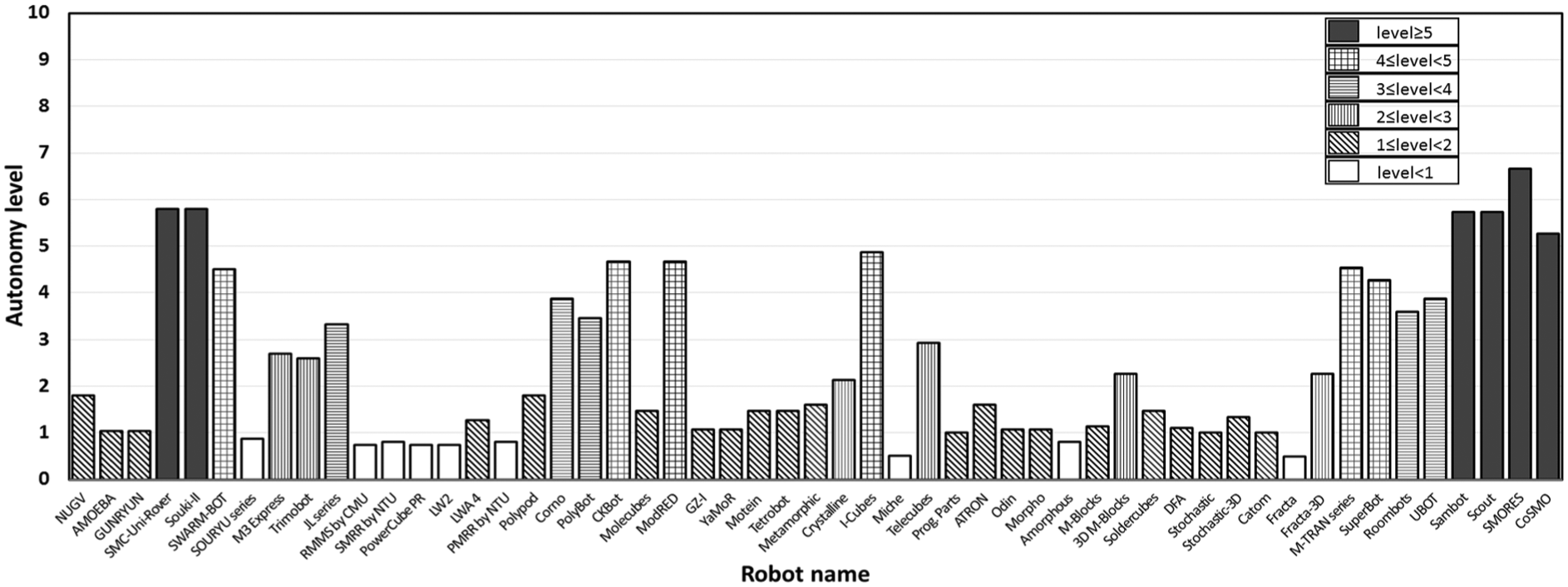
Evaluation results of autonomy level of RMRs.
Based on the evaluation result of autonomy level of the selected robots, the autonomy of macro-sized reconfigurable manipulators and mini-sized lattice-type RMRs are in low level. For macro-sized reconfigurable manipulators, most of them were designed to perform several certain tasks accurately and steadily so that the manual connection mechanism is conducive to the coupling stiffness, which results in the nonautomatic interfaces. For mini-sized lattice-type RMRs, the primary reason is that the characteristics of their modules are difficult to form efficient mobility configurations. Besides, some lattice-type modules, which were developed to verify the stochastic behaviors, were not equipped with the ability of locomotion. For mini-sized hybrid-type RMRs, most of them have a high level of autonomy. Because their modules have several DOFs and docking interfaces that can generate multiple locomotion modes, some new platforms69,70–72 have been designed with movable modules.
Key technologies and challenges
Modularity and reconfigurability are the most outstanding characteristics for RMRs. As mentioned above, modules are the basic elements, and their characteristics will directly determine the executive ability and transformation of the whole system. To design an appropriate module is still a challenging issue. Some fundamental design principles have been given to clarify the necessary technology of modules. The robot configurations are the system-level problem, which should be in conformance to the task and environment. A robust configuration has a close association with the capabilities of manipulation and locomotion. So, designing the optimizing configurations is a key issue. The kernal activity for a modular robot is to change its shape or morphology, which is the embodiment of adaptability and versatility. There is a need of a set of rules to plan the best conversion route from the initial configuration A to the target configuration B without collisions. From the point of view of the exhaustive search, the reconfiguration planning is a nondeterministic polynomial (NP) problem that searching cost increases exponentially with the number of modules. 87 Consequently, the self-reconfiguration algorithm is a tremendous challenge.
Design methodology of modules
The module design has a direct impact on the connectivity, controllability, flexibility, and power utilization of the whole system. There are some common design properties extracted from the presented RMRs as follows:
Modularization: The self-encapsulated module has its own microprocessor, actuators, and power supply, and its function and behavior should be independent.
Activity: Modules should have a certain driving ability, which guarantees modules to realize some movements.
Intelligence: Modules should have some perceptive abilities to detect the status of their own and the surrounding and can communicate with adjacent modules.
Standardization: Standard uniform component design can realize the interchange between modules, which is necessary to the system reconfiguration. For example, the docking interface plays a significant role in the mechanical and electrical connection between modules.
Serialization: Different serial of modules can enhance the applicability, and various functional configurations can be realized to meet the environment and mission requirements.
Study on configurations of robotic organisms
The configurations are the structural forms of RMRs, which closely influence locomotion, manipulation, and controllability of the system. Because of the diversity and complexity of tasks, it requires the adaptability and versatility in robot configurations. When the task is given, how to construct a goal configuration can be formulated as a complex combinatorial optimization problem. Synthesizing the current literature in this field, it is found that study on configurations contains several aspects: (1) configuration representation, (2) configuration design, and (3) configuration evaluation as detailed below:
Configuration representation. Topological information and features of the actual system should be expressed by a description mode. If the configuration representation can only offer a little information, it will be difficult to describe the current configurations; if the configuration representation offers excessive information, it will increase the complexity of the description. The representation should be scientific and rational as well simple enough. The current representation methods mainly include encoding, 88 assembly incidence matrix, 32 directed graphs, 39 and configuration matrix. 20
Configuration design. The optimal combination mode of modules should be established based on the corresponding relationship between working space environment × assignment (EA) and behavior space configuration × operation/gait (CO/G). The preliminary configuration should satisfy some performance tests (configuration evaluation) for being selected as the target configuration. Many kinds of optimization methods have been proposed to design the most optimal configuration. A configuration plan based on expert system was proposed by Sabin and Weigel 89 to design the target configuration, and Paredis and Khosla 90 adopted the method of simulated annealing algorithm. In addition, Chung et al. 91 applied the genetic algorithm to solve this question.
Configuration evaluation. It is necessary to assess the feasibility of configurations. The evaluation index should combine accessibility, operability, reconfigurability, mobility, obstacle avoidance, and the number of modules. Yang et al. 92 took the numbers of joint and link modules as the objective function and regarded the accessibility, operability, and mechanical–structural design requirements as the constraint condition to design an optimal configuration. Chen et al. 36 adopted the operability as the objective evaluation index, and considered the accessibility as the constraint condition to plan a configuration. As for multiple-task-oriented robots, the evaluation methods are also diverse.
Self-reconfiguration algorithms
Essentially, self-reconfiguration planning is the process of planning the sequence of primitive actions, discrete changes in joint angles, and connections. Before reconfiguration planning, a critical step is to recognize the current configuration 93 and then every module should identify their predefined locations in the target configuration, which requires the ability to sense neighbors and handle obstacles. At present, there is no general algorithm for self-reconfiguration planning because the particular module structure designs lead to different planning manners. Some specific algorithms have been only developed for the specified robots, for example, a centralized two-layer planner was developed for the M-TRAN system. 94
Applications and future directions
With the increasing requirements on transformation, dexterity, modularization, and reconfigurability, 95 recently, some RMRs provide us many innovative ways to meet the practical and future tasks. The department of the first two authors of this article, Shenyang Institute of Automation, Chinese Academy of Sciences (SIA-CAS), is the earliest robotic research institute in China. Many types of RMRs are developed in SIA, and some SIA designs will be introduced in detail in the following.
Disaster relief
Searching and rescuing in ruins is a tough job because the unstructured environment is dangerous to human lives. Liu et al.4,19–21 developed the AMOEBA-I in SIA-CAS, aiming to supply assistance in disaster relief work. The AMOEBA-I was equipped with various types of sensors to perceive the nearby environment. For example, the ultrasonic transducer was utilized to detect the obstacles on both sides of its body, the laser sensors were applied to acquire the information of front obstacles, the global positioning system (GPS) unit was installed to provide the current position information, and a microphone pickup and an IR camera sensor were selected to search the information for help. The caterpillar track mobile modules ensure a strong ability of ground movement, and nine convertible configurations enhance the adaptability to different terrains. As shown in Figure 5(a), the AMOEBA-I was searching the trapped people on the ruins of Ya’an earthquake in China.

(a) AMOEBA-I in Ya’an earthquake, (b) SIA 6-DOF RMR, and (c) SIA wheel-manipulator robots (courtesy of State Key Laboratory of Robotics, Shenyang Institute of Automation, Chinese Academy of Sciences, China).
Manipulator operation
To fulfill the requirements of multiple configurations in extreme environment, Pan et al. 96 conducted a project of modular manipulators for the goals of excellent capabilities of reconfiguration and operation in SIA-CAS. The standard electrical interface design can realize the connection of wires inside joints and assist the manipulator to identify the current configurations. The path matrix was proposed to solve the automatic kinematics modeling of multi-branched configurations. A method based on configurations’ library and task demands was proposed to design a target configuration. A 6-DOF manipulator was selected from the configurations’ library to verify the dexterity of the system as shown in Figure 5(b).
Planetary exploration
In the context of planetary exploration, Wang et al. 97 developed a wheel-manipulator robot in SIA-CAS to achieve the strong obstacle-traversing ability and the locomotion stability. The 6-DOF manipulator ensures an excellent manipulating capability (Figure 5(c)). The single wheel-manipulator robot as a module has two working modes: manipulator and mobile. It can be assembled into a multi-robot system with swarm intelligence to perform many superior maneuvers such as turning around, traversing obstacles, and changing configurations.
On-orbit service
For large-scale complex spacecrafts such as a large space station, it is very hard to accomplish the whole body launch in one mission. Therefore, the whole system should be divided into several parts to be launched into orbit in space. Space manipulators are the important operating tools in assembling and maintaining the space station to undertake multiple tasks. Because of the launch costs, the weight and volume of space equipments should be strictly controlled. A concept of using RMRs as the assembling tools for on-orbit services 98 is envisioned that astronauts can only carry a certain amount of modules to the space and then assemble them into multiple modular robots to fulfill specific on-orbit assembly tasks.
Conclusion
This article has reviewed the history and state of the art of RMRs. After analyzing various innovative designs, it can be found that the concepts of modularity and reconfigurability have been penetrating the design of all the RMRs. This article has made a detailed classification of the existing RMRs in Figure 1. The RMRs can be classified into two major categories: modular mobile robots and modular restructured robots. The two major categories can be further divided into several sub-categories: joint-motion robots and joint-reconfiguration robots; macro-sized reconfigurable manipulators and mini-sized reconfigurable or self-reconfigurable robots (chain, lattice, and hybrid types). Two comparative analyses have been demonstrated to clarify the typical characteristics of RMRs. These characteristics contain module shape, module DOF, module attribute, connection mechanism, interface autonomy, locomotion mode, and workspace. Advantages and weaknesses of different sub-categories have been discussed.
Furthermore, an evolutionary cobweb evaluation model has been proposed to assess the autonomy level of selected robots, and corresponding statistical results have been presented in Figure 4. The key technologies, the design methodology of modules and robot configurations, the challenge, and the self-reconfiguration algorithms were also summarized in this survey. Meanwhile, combined with the fundament research achievements in the first two authors’ department (SIA-CAS) and the future direction, several practical and potential applications have been introduced.
It is hoped that this article can help researchers to better understand the achievements and challenges of this field in the current phase and can stimulate the researchers’ greater enthusiasm for future research.
Footnotes
Acknowledgements
J.L. and X.Z. are co-first authors and equally contributed to the study.
Academic Editor: Yong Chen
Declaration of conflicting interests
The author(s) declared no potential conflicts of interest with respect to the research, authorship, and/or publication of this article.
Funding
The author(s) disclosed receipt of the following financial support for the research, authorship, and/or publication of this article: This research is supported by Basic Research Fund of China Manned Space Engineering, the Key Research Program of the Chinese Academy of Sciences (Y4A3210301), the National Science Foundation of China (51175494, 61128008, and 51575412), and the State Key Laboratory of Robotics Foundation.