
Abstract
To satisfy the requirements of large workspace, high capability, and low inertia demanded by the high precision and high stiffness aerospace equipment, serial manipulator with insufficient intersection joints is proposed in this article based on finite and instantaneous screw theory. Due to the specific topology structure with no intersecting joints at both ends, the explicit solution of forward and inverse kinematics for the serial manipulator with insufficient intersection joints proposed in this article is extremely difficult. Therefore, an analytical method based on finite and instantaneous screw theory is proposed for this serial manipulator, and the explicit kinematic solution is derived in this article. According to particular calculation principle of finite and instantaneous screw theory, the finite motion of this serial manipulator is described. Based on this description, the product of exponentials formula of the kinematics of the serial manipulator with insufficient intersection joints is established on the basic of finite and instantaneous screw theory for the first time, and a novel subproblem is arose during the decomposition of product of exponentials formula. Regarding this issue, an innovative approach to this subproblem is proposed by introducing the new Paden–Kahan subproblem with elimination, and the explicit solution for the inverse kinematics is derived. Finally, the numerical examples are simulated, and the correctness of the method proposed in this article is verified.
Introduction
With the acceleration of space exploration by countries around the world, aerospace equipment is constantly being updated. As one of the most important equipment supporting space science, the space manipulator mainly provides orbital services such as target capture, racemization, rotation, and insertion. 1 –4 At present, the space manipulators used on space stations in various countries are composed of serial mechanisms or multiple serial mechanisms, which have the advantages of large workspace, high flexibility, and high attitude. However, as space exploration continues to deepen and space operations become more complex, serial mechanisms will face enormous challenges in meeting the demand for high precision and high stiffness tasks.
In the light of this problem, Song et al. 5 proposed a hybrid mechanism configuration by combining a serial mechanism with a parallel mechanism of high stiffness and precision, where the parallel mechanism is installed at the end of the serial mechanism. The configuration with the advantages of large workspace, high flexibility, high stiffness, and high precision was provisionally achieved, and an integrated analysis of the parallel mechanism was conducted. Based on the hybrid mechanism of the above model, Zhang and Qi 6 synthesized the configurations of the serial mechanism and the parallel mechanism, respectively, and topologically developed various novel configurations that allow further optimization based on performance requirements. Therefore, it is of great significance to carry out relevant research on this type of hybrid mechanism as a new field of innovation and development for mechanism science in space manipulators.
Due to the great advantages of high precision, high stiffness, and large workspace combined with the hybrid manipulator, it has developed very rapidly. 2,7,8 The hybrid mechanisms could be classified into three categories according to their structural character: The first type is using the parallel mechanism as a base to connect the serial mechanism. The second type is a combination of several parallel mechanisms. The third type is using the serial mechanism as a base to connect the parallel mechanism. The first type of hybrid mechanism is represented by the Tricept robot, which has high precision, high stiffness, and a large workspace, and is widely used for high-speed machining. 9 –11 The second type of hybrid mechanism is limited by the complexity of the structure, and most research is still at the theoretical or experimental stage. 12 –15 The third type of hybrid mechanism has limited research due to the high-end load requirements of the serial manipulator and the high degree of implementation difficulty.
Although the first type of hybrid mechanism is relatively mature, it still does not have the same flexibility and workspace as a serial manipulator of the same size. Besides, the cramped working environment inside the space station is not suitable for the use of such a hybrid manipulator. The second type of hybrid mechanism significantly improves its workspace and flexibility compared to the first, but this complex system is also more affected by various uncertainties in space. The third type of hybrid mechanism perfectly inherits the advantages of both the serial mechanism and the parallel mechanism. The space manipulator is almost unaffected by gravity in the space station environment, which means that the installed parallel mechanism has a relatively minimal effect on the end of the serial manipulator, making it suitable for use as a space manipulator. During operation, the serial manipulator performs a wide range of motions, while the parallel mechanism compensates for precise positioning.
Thus, the research team obtained a variety of novel topological configurations by the configuration synthesis method and proposed a five-degree of freedom (DOF) topological configuration of the serial mechanism with insufficient intersection joints. This configuration has a relatively low inertia while maintaining dexterity. The multiple joints of the manipulator are offset to increase its foldability. The single joints were designed on both sides of the manipulator to reduce the motion coupling between the parallel mechanism and serial mechanisms, thus reducing the difficulty of analyzing the hybrid mechanism. However, due to its peculiar structure, it is little studied and no relevant kinematic modelling is available, so the kinematic analysis of this mechanism is taken as the research object in this article.
The forward kinematics of serial manipulators is relatively simple, and the D-H method and the screw method are commonly used. 16 Whereas the inverse kinematics of serial manipulators is more complex, the solution methods can be divided into two categories: the numerical method and the algebraic method. The numerical method is suitable for almost all manipulators, but the calculation results are influenced by the initial values. 17 –19 The analytical method is more numerically stable than the former, including the geometric method and the algebraic methods, both of which depend on the structural characteristics of the manipulator in terms of the difficulty of the solution. 20
Paden–Kahan is a geometric approach to the inverse kinematics of a manipulator that is efficient and ready to model but is limited by the manipulator not having enough intersecting joints. The earlier studies 21 –24 created novel Paden–Kahan subproblems according to the nonintersecting joints of the specific manipulator in obtaining the inverse solution and provided the solution process. Chen and Gao 25 proposed an equivalent motion technique, which transformed the kinematic equation of the manipulator into the standard form by replacing the sequential of the kinematic pair, and solved it with classical Paden–Kahan subproblems. Wang et al. 26 proposed a method that combines elimination to reduce the dependence of simple subproblems on intersecting joints.
Modern mechanism research has found that the continuous motion of any rigid body is essentially Chasles’ motion, and the finite and instantaneous screw (FIS) theory contains the basic elements of Chasles’ motion, which reveals the simplest characterization of the continuous motion of a mechanism, and provides an integrated method for studying the mechanism. 27 –30 In addition, this theory rigorously derives the differential mapping relationship between continuous and instantaneous motions, which allows configuration synthesis, kinematics, dynamics, and parameter optimization to be carried out under a unified mathematical framework, which is conducive to the integrated analysis of the mechanism. 31
Therefore, in this article, the kinematics of a serial manipulator with insufficient intersecting joints is carried out based on FIS theory. The product of exponentials (POE) formula of the serial manipulator with insufficient intersecting joints is established analytically and explicitly for the first time based on FIS theory. Regarding the lack of explicit inverse kinematics solution for this manipulator without intersecting joint at both ends, an innovative approach is proposed by introducing the new Paden–Kahan subproblem with elimination, and the explicit inverse kinematics is derived based on FIS theory.
Finite screw and forward kinematics model
The kinematics of the manipulator mainly analyzes the end pose relative to the initial pose of the manipulator from the perspective of mechanism. First, considering the position of a rigid body in space, defining {S} as the inertial coordinate system at the initial position and {T} as the coordinate system fixed to the rigid body, the orientation of the rigid body is represented by the rotation matrix

Pose of rigid body in space.
Chasles and Poinsot proved that any motion of a rigid body is equivalent to movement along and rotation around a certain line in the space, which is commonly called screw motion. With the development of modern mechanism kinematics, this motion can be expressed clearly and intuitively by FIS theory. 32 For continuous of any rigid body, where

where

Finite screw.
For a serial manipulator composed of n joints, there are n

where “

The finite screw of the rigid body is extended to the forward kinematics of the manipulator with n DOFs. Defining

Forward kinematics of the manipulator
To obtain the forward kinematics equation of the manipulator, selecting the axis of each joint, the initial and end position of {S} and {T} as shown in Figure 3.
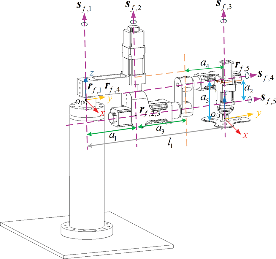
Twist coordinate system of the manipulator.
The angles of each joint are 0, and the initial pose of the manipulator is

Establishing the twist on each joint relative the inertial coordinate system as

Selecting a point on the axis of each joint as

From the expression of the finite screw based on FIS theory, the unit twist on each joint be obtained as

According to equation (4), the forward kinematics model is established

Inverse kinematics analysis
Inverse kinematics based on Paden–Kahan subproblems
The kinematic model of the manipulator based on the POE formula can be divided into several Paden–Kahan subproblems to solve the inverse problem by simplifying the kinematic model. These subproblems are actually some geometric problems with clear meaning, and Paden and Kahan have proposed three subproblems and provided solutions. (1) Subproblem 1: rotate around a fixed axis.
As shown in Figure. 4, the point p in space rotates θ around a fixed twist


Paden–Kahan subproblem 1.
(2) Subproblem 2: rotate around two intersecting fixed axes sequentially.
As shown in Figure 5, there are two intersecting fixed twists


Paden–Kahan subproblem 2.
(1) Subproblem 3: rotate around a fixed axis until it is a specified distance from a point.
As shown in Figure 6, the point p rotates around the twist


Paden–Kahan subproblem 3.
Standard industrial serial manipulators have a wrist joint composed of three intersecting rotating joints. Models as shown in Figures 7 and 8, the wrist joint of two common industrial manipulators is designed at its end position and initial position, respectively, which can facilitate the adjustment of orientation in space. The other three joints cooperate with each other to allow the end-effector to reach any pose in space.

Manipulator model with anterior wrist joint.

Manipulator model with posterior wrist joint.
To solve the inverse kinematics problem for these manipulators, it is usually necessary to first simplify the twists on all intersecting joints in the POE formula according to the principle of position invariance. Then the twist of the first set of simplified intersecting joints is eliminated according to the principle of distance invariance. The POE formula is divided into several Paden–Kahan subproblems, and the inverse kinematics of the manipulator can be expediently obtained by substituting equations (10) to (16), the modeling process is shown in Figure 9.

Inverse kinematics modeling process of manipulator.
The kernel problem of the manipulator with insufficient intersection joints
The classic Paden–Kahan subproblems be used to solve the manipulator with enough intersecting joints at initial and end position. In the manipulator studied in this article, joint 1, joint 2 and joint 5 are parallel, while axis 3 and axis 4 are parallel, and there are no intersecting joints at either end. The following problems arise during the simplification process: Multiple twists cannot be simplified simultaneously through the principle of position invariance. Twists cannot be eliminated sufficiently through the principle of distance invariance.
The two points above make it impossible to convert the POE formula into classical Paden–Kahan subproblems. Therefore, elimination combined with screw is proposed to obtain the inverse solution according to the characteristics of this manipulator. In equation (9), the twist

Paden–Kahan subproblem 2 expansion.
Defining vector

Squaring the norm on both sides of equation (17)

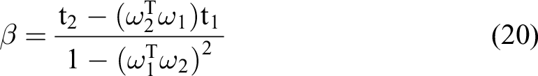
Based on the geometric relationship of the intersection of spheres, the parameters in equation (16) can be obtained, and point q can be solved by combining equations (19) to (21)


Inverse kinematics of the manipulator
Solutions of Θ5, Θ2, and Θ3
In equation (9),


Moving the known quantity to the right of equation (9), and the equation on the left only contains the unknown quantity as


Selecting a point in the direction of the joint axis, the position of a point on the axis of rotation around the axis remains unchanged as

Selecting


Equations (30) and (31) correspond to the form of Paden–Kahan subproblem 2 expansion, which involves rotating around two intersecting and noncoincidence twists in sequence until the distance from point q in space is

Solving the intersection point

Equation (33) is equivalent to two Paden–Kahan subproblems 1, solving


Solutions of Θ1
Substituting known quantities

Equation (38) corresponds to the form of Paden–Kahan subproblem 1, solving

Solutions of Θ4
Moving the known quantity

Equation (40) corresponds to the form of Paden–Kahan subproblem 1. Solve

Simulation and verification
Simulation and verification of forward kinematics
The parameters of each link of the manipulator are as

The forward kinematics formula of the manipulator is written into MATLAB, giving a set of joint angles and programming the trajectory function, plotting the Cartesian trajectory of the tool coordinate system relative to the inertial coordinate system. Enabling the motion plug-in in SolidWorks and adding motors to the 3D model and input the same set of joint angles. Adding a diagram of the trajectory of the end position of the manipulator in space and importing the data into MATLAB. The process is shown in Figure 11.

Forward kinematics simulation process.
In the initial position of the manipulator, all joint angles are set to 0. Given a set of joint angles as the motion trajectory of the manipulator to validate the POE model as equation (42)

As shown in Figure 12, the forward kinematics model established by the POE formula based on the FIS theory matches the trajectory of the 3D model in SolidWorks in three directions in space, which verify the correctness of kinematics model.

End-effector position in space.
As shown in Figure 13, the error of the position is negligible, which confirms the accuracy and efficiency of this forward kinematic model.

The error of position.
Simulation and verification of inverse kinematics
Paden–Kahan subproblems are to solve the inverse solution of manipulators based on geometric methods which are the closed form solution of manipulators. According to subproblem 2, the value of q can be two sets, one set, and no solution. Ideally, each group of
To verify the correctness and accuracy of the inverse solution, joint and Cartesian trajectory two method are used for simulation. (1) Joint trajectory: To simplify calculations, assume that each joint maintains a constant velocity, the joint trajectory as

In equation (43), i represents each joint. Substituting m into equation (9) to calculate the trajectory of the manipulator in Cartesian space, and then calculating the sequence of joint angles through inverse kinematics algorithm proposed in this article. Comparing the calculated results with the initialized joint trajectory m, as shown in Figure 14.
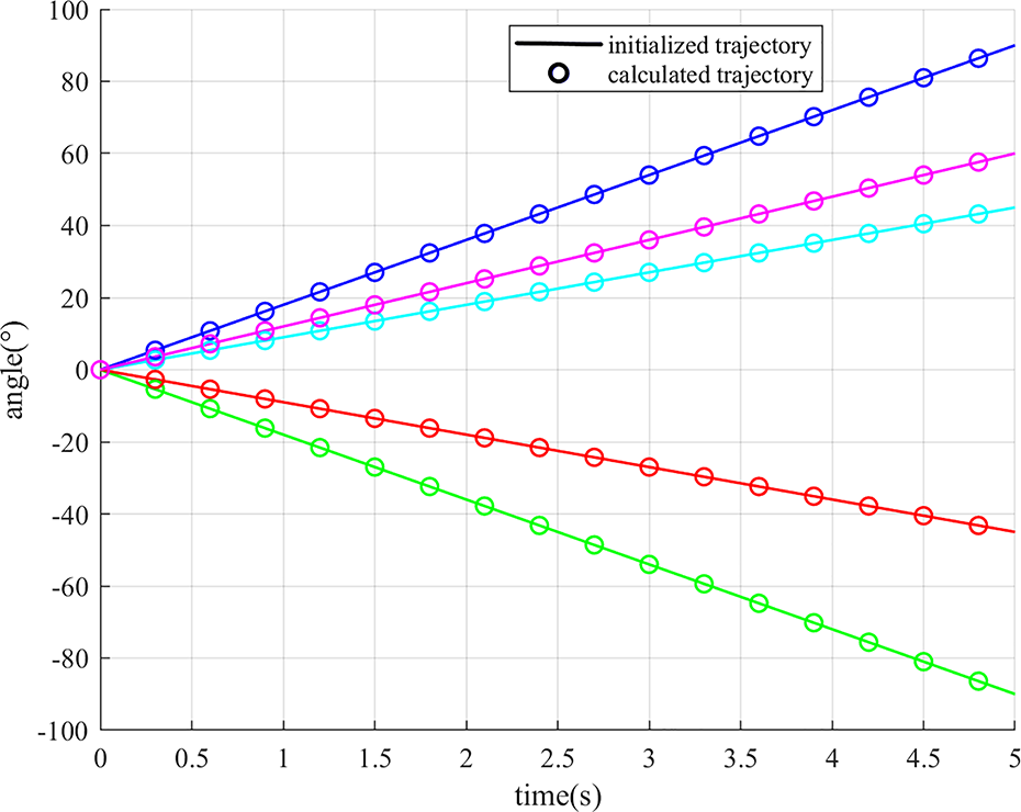
The joint trajectory of the calculation and m.
As shown in Figure 15, the error of each joint is calibrated.

The error of each joint.
(2) Cartesian trajectory: Given a Cartesian trajectory as

Similarly, assume that each joint maintains a constant velocity,

The sequence of joints angle.
Substituting the calculation into equation (9) to obtain the trajectory of the manipulator, comparing the calculated results with the initialized Cartesian trajectory n, as shown in Figure 17.

The Cartesian trajectory of the calculation and n.
As shown in Figure 18, the error of each position is calibrated.

The error of the position.
Based on the simulation results above, the error of joints and position is very small and can be ignored, which indicates that the inverse kinematic algorithm proposed in this article has high accuracy.
Conclusion
To meet the requirements of on-orbit missions for large workspace, high stiffness, and high precision, the kinematics of a serial manipulator without insufficient intersection joints is analyzed based on the FIS theory in this article. The main contributions are as follows: Based on the FIS theory, the continuous motion of the manipulator is described, and the POE formula for a serial manipulator is established for the first time by using the triangular product algorithm of finite screw. In the process of establishing the inverse solution model of the manipulator, an innovative method combining elimination with the expansion of Paden–Kahan subproblem 2 is proposed to solve the new subproblem caused by the structural characteristics of the manipulator without intersection joint on both sides, and the explicit solution is given. The correctness of the kinematic model based on FIS theory is verified through simulation, and the end error of the manipulator is verified to be within a reasonable range by two numerical examples.
Footnotes
Declaration of conflicting interests
The author(s) declared no potential conflicts of interest with respect to the research, authorship, and/or publication of this article.
Funding
The author(s) disclosed receipt of the following financial support for the research, authorship, and/or publication of this article: This work was supported in part by the National Natural Science Foundation of China under Grants (51905378 and 52175243), in part by the Tianjin Science and Technology Plan Project 22JCYBJC01670 and Project 21JCZDJC00820, in part by the Tianjin University Science and Technology Development Fund Project 2020KJ105, in part by the Scientific Research Foundation of Tianjin University of Technology and Education under Grant KYQD1901.