
Abstract
This article proposes a novel inverse kinematic approach with translation transformation matrix based on screw theory to solve the inverse kinematic problem for 6R robot manipulator with offset joint. The translation transformation matrix is introduced to convert the 6R robot manipulator with offset joint to a new configuration with intersecting axes, and the mapping relationship from the end effector to the joint angle is established along with the Paden–Kahan subproblems. The eight closed solutions of the specific configuration are deduced, which automatically eliminate the singularity solutions. Moreover, the precision and efficiency of the proposed method are verified through a numerical example. Unlike other approaches, the presented algorithm not only inherits the superior accuracy of the other geometric approaches but also exhibits an outperform efficiency. Finally, the method is generalized to other 6R robots, which has closed-form solutions to further verify its versatility. The presented study provides some basis for further investigations, such as trajectory planning and motion control, which provides a new tool on the analysis and application of this kind of robot manipulator.
Keywords
Introduction
Industrial robot is widely used in automation production line and has become an essential core automation equipment in industrial manufacturing field. As the basis of the workspace analysis, trajectory planning, motion control and off-line programming for the industrial robot and robot kinematics including forward kinematic and inverse kinematic, plays an important role in the field of robotics. Robot kinematics with high efficiency and precision, which can significantly improve the motion performance of robot, attract extensive attention in academia. The kinematic solving methods of robot at different mechanical configurations can be divided into two categories. One of which has a clear mathematical model, such as the Denavit–Hartenberg (D-H) method 1 and the product of exponentials (POE) approach based on screw theory. 2 The other, however, has no such clear mathematical model, such as the fuzzy logic control, genetic algorithm, neural network, and weighted least-norm approaches with self-motion variables. 3 –6 The former performs a relative higher accuracy and efficiency and is extensively applied in the automation production. The latter is suitable for solving high dimensional and nonlinear problems and is mainly used for the redundant robot in complex operation condition, but the drawbacks of accumulative errors and time-consuming are the urgent issues. 7
In the field of industrial robot, the kinematic solving methods with clear mathematical model are widely used, especially the D-H approach. 8 –12 Although the D-H method is quite popular, it has several disadvantages. For instance, the singular solutions would be emerged, if the adjacent joints are near parallel. In that case, a slight kinematic perturbation will cause significant variations in the kinematic parameters. 13 Moreover, each joint needs to establish a coordinate frame. The complexity of the mathematical model and the accumulated errors with adjacent joints will grow exponentially with the complicated structure. To overcome these problems, the POE approach based on screw theory is developed, which indicates that a rigid body can be moved from any one position to any other by a movement consisting of rotation about a straight line followed by translation parallel to that line. 2 Comparing with the D-H method, the POE approach based on screw theory has a simpler mathematical model with only two coordinate frames for the entire chain, wherein the frames can be arbitrarily chosen. The joint variables may represent actual displacements of the robot. 14 Moreover, the singular solutions are automatically eliminated, and the Jocobian matrix is directly formed by the normalized screws on each joints. Due to the above characteristics, the POE approach based on screw theory is widely applied to solve the inverse kinematic problem (IKP) for robot with multi-degree of freedom (DOFs). The core thought of this method is to decompose the complex IKP of the multi-DOFs mechanism into several known subproblems. Such as the Panden–Kahan (PK) subproblems. 15,16 However, this method has some limitations in solving the IKP of the robot manipulator with offset joint. Aim to address these limitations, many novel approaches have been presented in recent years. Kucuk and Bingul 17 developed a new inverse kinematics algorithm based on the D-H method for the robot manipulators with offset wrists. The relatively higher efficiency and precision are exhibited against with the Newton–Raphson method. Liu et al. 18 presented an efficient inverse kinematics approach based on the D-H method for the PUMA560 robot with offset joint. The complex inverse kinematic matrix equations are transformed into eight algebraic equations to make the solving compact. Fu and Tang 19 provided an efficient method based on Geometric Algebra for the 6R robot manipulators with offset wrists, and all 16 solutions are yielded. However, the singularities, joint limitations, and optimum solution of robot manipulator are not fully taken into consideration. Moreover, literature reveals that a large proportion of the innovation for this issue is based on the traditional PK subproblems, which combined with the other analytical, geometric, and algebraic methods. Chen et al .20 adopted an improved subproblem method along with PK subproblems to describe the rotation about three axes, which is distributed in different surfaces. The reliability and real-time properties are verified. Sung et al. 21 introduced a generalized solution by analyzing the PK subproblems 1 and 2 for all cases in space with the skew coordinates. Zhao et al. 22 designed a geometric method in combination with the PK subproblems to avoid the singular solutions when the adjacent joint axes are parallel or close to parallel. In this method, the IKP for the former three consecutive joint axes with noncoplanar is addressed by a new geometric approach, and the others are calculated by the traditional PK subproblems. The correctness and high accuracy of this algorithm are investigated. Moreover, the Wu’s method and Sylvester resultant are introduced in IKP by Lv et al. and Li and Xie, respectively, to solve the IKP of the robot with offset joint through algebraic elimination. 23,24 The correctness of this kind of algorithm is discussed, but the solutions are relatively complicated, and the time-consuming is an urgent issue.
From the above reviews, it can be found that plenty efforts have been carried out to solve the IKP for the robot with offset joint in the past years. Although many research have been conducted for this kind of problem, several deficiencies are remaining unresolved, for example, the published models exposed relatively high complexity, and the accuracy and efficiency are needed to be further verified. To overcome the existing limitations and expend its application, a novel inverse kinematic approach with translation transformation matrix (NIKA-T) is proposed for the 6R robot manipulator with offset joint. This kind of robot has closed-form solutions, the first three consecutive joint axes distributed in different surface, and the last three joint axes intersecting at a common point, as shown in Figure 1. The mathematical model is established, and the inverse kinematic of the specific configuration with NIKA-T is deduced. Moreover, the experiment and verification of the NIKA-T are conducted, and the computational accuracy and efficiency based on this approach are certificated by comparing with the other geometric algorithm, the dual quaternions (DQ) algorithm, and the traditional D-H approach. The feasibility of the NIKA-T is analyzed through a practical application in the trajectory planning, and the superior properties are further certificated. Finally, the method is generalized to other 6R robots, which has closed-form solutions, and the versatility is further verified.
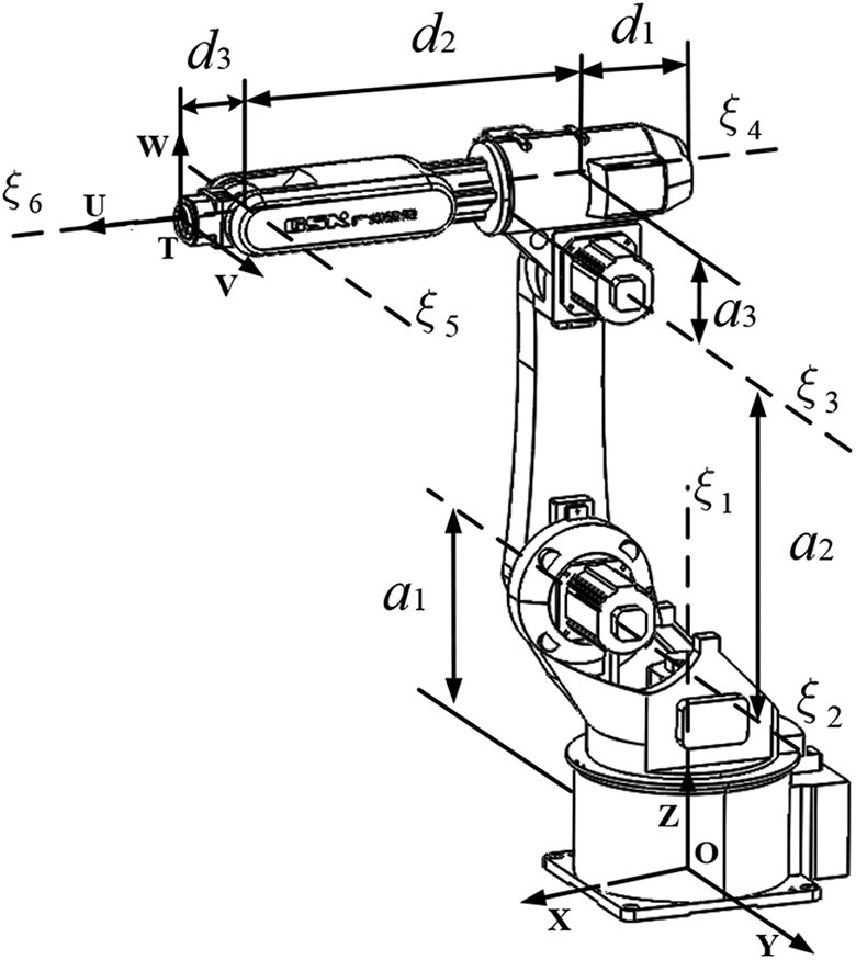
Kinematic definitions for the 6R robot manipulator with offset wrist.
To present the novel approach in detail, the remaining part of this article is organized into the following sections: The second section deduces the inverse kinematic of the specific configuration based on the NIKA-T. The third section demonstrates the computational accuracy and efficiency of the proposed method through an example analysis. The fourth section proposes a practical application with the NIKA-T for a specific working environment. The fifth section generalizes this kind of approach to other 6R robots. The sixth section provides the conclusion of the article.
NIKA-T for 6R robot with offset joint
The 6R robot manipulator with offset joint is shown in Figure 1. O-XYZ and T-UVW represent the base coordinate frame and the tool coordinate frame of the robot, respectively.
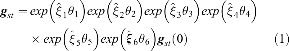
The forward kinematic is to determine the position and attitude of the end effector by choosing a set of joint angles within the workspace. As shown in Figure 1, the forward kinematic of the robot can be obtained by combining with the movement of each joint successively according to the screw theory. 2
where
In contrast to the forward kinematics, inverse kinematic is a completely opposite problem, which aims at calculating the joint angles by giving a desired pose matrix

Solution process for the IKP with NIKA-T. IKP: inverse kinematic problem; NIKA-T: novel inverse kinematic approach with translation transformation matrix.
Firstly, solve θ1 by determining the intersecting point
Solving θ1
As shown in Figure 2,

Hereinafter,
Assuming that

Translation transformation
On this basis, the translation transformation matrix is introduced to convert the 6R robot manipulator with offset joint to a new configuration with intersecting axes, as shown in Figure 3. And then, the PK subproblems are used to solve the remaining joint angles based on the new configuration.

Schematic diagram of the 6R robot manipulator with two configurations.
As shown in Figure 3(a), the IKP of the former three consecutive joint axes with noncoplanar cannot be solved by the traditional PK subproblems. By analyzing this kind of mechanical configuration, we found that the structure with offset joint (Figure 3(a)) can be transformed to a new configuration without offset joint (Figure 3(b)) by translating the end effector along the XOY plane. To be specific, the end effector can be translated with d 1 along the projection direction of the rigid link along the XOY plane between the joint 1 and joint 2 after rotating θ1 along axis 1. After that, the mechanical configuration of Figure 3(a) is translated to the Figure 3(b), and the IKP of the new configuration can be completely calculated based on the PK subproblems.
As shown in Figure 3, let

According to the Figure 3(b), with the translation transformation, the point on each axis is changed as follows

Hence, the initial pose matrix of the robot related to the base coordinate frame S-XYZ can be expressed as

Solving θ3
Substituting equation (4) into equation (2), we have

where

The θ3 can be calculated with the PK subproblem 3.
As shown in Figure 4, equation (7) can be further expressed as follows

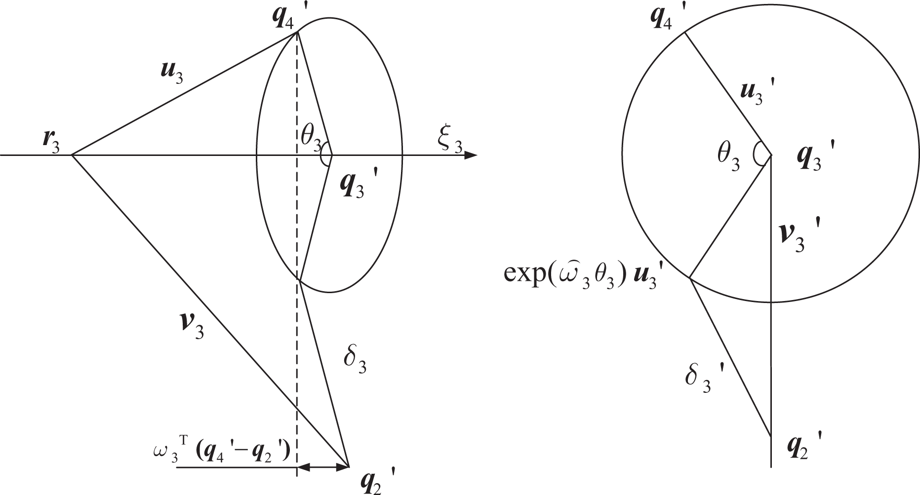
Geometric diagram of the subproblem 3.
We define
According to the PK subproblem 3, we have


Thus, the θ3 can be given as follows

Solving θ2
From equation (6) and the point

Assuming that

The θ2 can be calculated with the PK subproblem 1.
As shown in Figure 5, equation (11) can be further expressed as follows

Geometric diagram of the subproblem 1.
We define


According to equation (13), the θ2 can be obtained as follows

Solving θ4 and θ5
In equations (1) and (4) with the known θ1, θ2, and θ3, we have
We define

Assuming that

The θ4 and θ5 can be calculated with the PK subproblem 2.
As shown in Figure 6, equation (16) can be further expressed as follows


Geometric diagram of the subproblem 2.
If we define the axes of the fifth and sixth joints intersecting at point

According to the subproblem 2, the θ4 and θ5 can be determined as follows

Namely

Solving θ6
From equation (15) and the known

Let

where
Let

The θ6 can be calculated with the PK subproblem 1

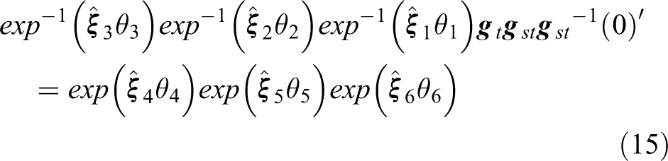
Until now, the closed solutions of inverse kinematics
Experiment and verification
The kinematic solutions of the GSK-RB20 robot manipulator are deduced to verify the correctness and efficiency of the NIKA-T. The structure parameters of the robot are given as follows (in millimeter)

We select a pose of the robot to clamp the workpiece in a specific working condition as the research object.

According to equation (1), the forward kinematic of the end effector is obtained with the given
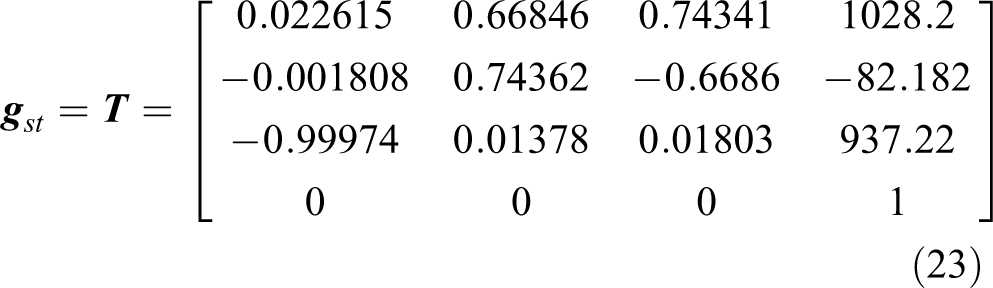
Then, based on the NIKA-T and the obtained pose matrix, the eight groups of angles are calculated, as shown in Figure 7. After that, each group is utilized to solve the forward kinematic by equation (1), and the computational errors are derived by comparing with equation (23). All calculations are conducted in MATLAB programming.

Eight solutions of inverse kinematic with the NIKA-T: (a) group 1, (b) group 2, (c) group 3, (d) group 4, (e) group 5, (f) group 6, (g) group 7, (h) group 8. NIKA-T: novel inverse kinematic approach with translation transformation matrix.
As shown in Figure 7, eight solutions of inverse kinematic with the NIKA-T are deduced, wherein the first solution is exactly the same as the given

where


According to equations (25) and (26), the maximum and minimum computational error are given in the order of 10−10 and 10−12, respectively, which can fully meet the requirement of the robot control precision.
As mentioned above, aim to solve the IKP for the robot manipulator with offset joint, many novel approaches have been presented in recent years. To verify the precision and efficiency of the NIKA-T, this article selects the D-H transformation method (DH), the geometric approach in combination with the PK subproblems (G-PK), and the DQ algorithm as the research objects to solve the IKP of the GSK-RB20 robot manipulator. 18,22,25 The solutions of the NIKA-T are compared with the DH, G-PK, and DQ, wherein the first group solution as the reference, and the result with accuracy to five decimal places. The efficiency of the four approaches and the running environment are shown in Figure 8 and Table 1, respectively.

Kinematics solution times of the proposed four approaches.
Running environment.

As shown in Table 2, due to the proposed NIKA-T, G-PK and DQ are all based on the geometric approach, only needs two coordinate frames. While the DH-based approach needs to establish a coordinate frame on each joint axis, the accumulated error with adjacent joints is increased with the complexity of the mechanical structure. The NIKA-T, G-PK and DQ, exhibits higher computational precision than the DH approach.
Inverse kinematic solution precision of the proposed four approaches.
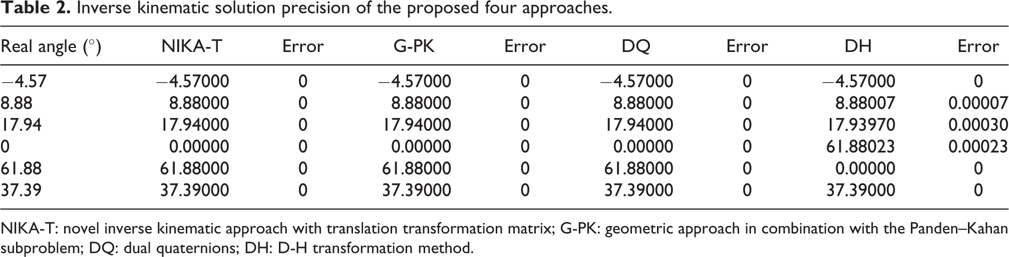
NIKA-T: novel inverse kinematic approach with translation transformation matrix; G-PK: geometric approach in combination with the Panden–Kahan subproblem; DQ: dual quaternions; DH: D-H transformation method.
As shown in Figure 8, the computing time of the forward kinematic and inverse kinematic by the four methods is compared. In the forward kinematic, the four kinds of approaches exhibit high efficiency, the computing times are 0.00096 s, 0.00096 s, 0.00064 s, and 0.00012 s, respectively, which are all limited in the order of 10−4. However, the computing time of the IKP based on the NIKA-T, G-PK, DH, and DQ are quite different, wherein the DH takes up 0.36898 s due to the relative tedious transformation model. The G-PK takes up 0.06705 s, since most of the time are consumed for solving the former three joints. The DQ also takes up 0.01064 s. However, the IKP with the NIKA-T only takes up 0.003010 s, which is reduced by 99.2%, 95.5%, and 71.1% compared with the DH, G-PK, and DQ, respectively. The high efficiency of the proposed algorithm is verified by the experiment.
Practical application of the NIKA-T
Calculation of the trajectory of the industrial robot manipulator with high precision and efficiency is important for efficient production. 26 In this section, a practical application of the trajectory planning based on the NIKA-T is conducted for further verifying its feasibility. Trajectory planning is a common and effective method to improve the kinematic efficiency, stability, and obstacle avoidance of robots. Aim at the industrial robot manipulator, the trajectory planning mainly includes two aspects. One is to select several discrete points in cartesian space and interpolate each reference point to realize the continuous and smooth motion control. The other is to choose many groups of joint angles for interpolating in joint space. The motion trajectory in the former approach can be fully controlled comparing with the latter one. But the pose matrix of the selected discrete points needs to be transferred to the joint space in real time, which requires the inverse kinematics algorithm with high computational accuracy and efficiency performance. In view of this, we design a trajectory to realize the pick-up and place motion for a workpiece. The designed trajectory contains 55 discrete points, which generated with Bezier curve. 27 The Cartesian coordinate of each point with the desired pose matrix of the end effector is calculated. The inverse solutions of these poses are derived with the NIKA-T. Moreover, the least squares method is taken into consideration to obtain the optimum solutions, 28 as shown in equation (27).
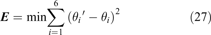
where
On this basis, the motion trajectory of the robot is obtained. Six reference points are listed in Table 3, and the pose information from 1 to 6 successively represents the states of initial position, moving to workpiece, clamping workpiece, moving to CNC machine, avoiding obstacles, and placing workpiece. The diagram of these states is shown in Figure 9.
Pose information of six discrete positions.


Motion diagram of the pick and place task: (a) initial position, (b) moving to workpiece, (c) clamping workpiece, (d) moving to CNC, (e) avoiding obstacles, (f) placing workpiece.
As summarized in Table 3, six reference points are selected to pick up and place the workpiece to the chuck of the CNC machine. The obstacle avoidance is taken into account in the planning. To realize the continuous and smooth of the motion trajectory, the Bezier curve is carried out to interpolate these reference points. And then, the 55 discrete points are generated. The inverse kinematics of these poses are derived with the NIKA-T in the final, and the pick and place task is completed, as shown in Figure 9.
As shown in Figure 9, the blue line represents the planned path with the provided method. According to the presented algorithm and combined with the trajectory planning, the pick and place task can be completed with high precision, and the computing time with the NIKA-T is 0.16602 s. The experimental results further prove the accuracy and efficiency of the presented algorithm and provide some references for practical engineering application.
Discussion
In this article, we only consider a configuration of 6R robot manipulators. Similarly, we aim at the configuration of the 6R robot manipulator, which has closed-formed solutions, that is, the robot configuration conforms to the “Pieper criterion.” The proposed approach can also be generalized to this kind of 6R robot manipulator.
The core step of the NIKA-T is to transform the original configuration with offset to a new one without offset, such that the PK subproblems can be applied to find the remaining joint angles. Therefore, it’s critical to find the translation transformation direction under the final pose matrix of end effector. As described in Solving θ1 section, the translation direction is determined by the previous joint angle of the offset link. We aim at the 6R robot manipulator, which has closed-formed solutions. These configurations require three consecutive joint axes parallel or intersected a common point, which provide the conditions to directly calculate the rotational angle of the offset link. On this basis, the proposed approach can be generalized to other 6R robot manipulators, which has closed-formed solutions such as the universal robot (UR) manipulator with offset joint, as shown in Figure 10. The specific solution process is described as follows.
Step 1: Solve θ1 by determining the intersecting point
Step 2: Transform the original configuration with offset to a new one without offset along the direction of the joint 1 to joint 2.
Step 3: Based on the new subproblems in Kong et al.,
29
which aim to solve the problem of the two parallel axes to a given point. The θ3 and
Step 4: Solve θ2, θ5, and θ6 successively based on the PK subproblem 1.

Schematic diagram of the UR manipulator with two configurations: (a) with offset joint, (b) without offset joint. UR: universal robot.
As mentioned above, the NIKA-T can be generalized to other 6R robot manipulators, which has closed-formed solutions, such as the UR manipulator with offset joint. Moreover, if the robot manipulators have no closed-formed solutions, that is, the robot configuration doesn’t conform to the “Pieper criterion,” the NIKA-T can also be utilized to build the relationship among the joint variables. The transcendental equations containing multiple variables are turned into a nonlinear equation containing one variable, and the IKP can be obtained by using one-dimensional iterative search.
Conclusion
In this article, we proposed a NIKA-T based on screw theory to solve the IKP for 6R robot manipulator with offset joint. The translation transformation matrix is introduced to convert the 6R robot manipulators with offset joint to a new configuration with intersecting axes. The inverse kinematic of the new configuration can be completely calculated based on the PK subproblems, and the computational errors are limited at the order of 10−10 to 10−12. Moreover, the experiment and verification of the NIKA-T are conducted, three kinds of approach with DH, G-PK, and DQ are given to compare with the presented algorithm, and the results show that the proposed method not only inherits the superior precision of the other geometric approaches but also exhibits a relative better efficiency. Finally, a practical application and the generalization of the novel approach are conducted and the versatility and the feasibility are further verified, respectively. The present study provides some basis for further investigations, such as trajectory planning and motion control, and takes some references for incorporating it in commercial software for the practical applications.
Footnotes
Acknowledgements
The authors acknowledge the support of the National Natural Science Foundation of China under Grant 91748208 and the Department of Science and Technology of Shaanxi Province under Grant 2017ZDL-G-3-1.
Declaration of conflicting interests
The author(s) declared no potential conflicts of interest with respect to the research, authorship, and/or publication of this article.
Funding
The author(s) disclosed receipt of the following financial support for the research, authorship, and/or publication of this article: This study was supported with funding from the National Natural Science Foundation of China under Grant 91748208 and the Department of Science and Technology of Shaanxi Province under Grant 2017ZDL-G-3-1.