
Abstract
The proposed study provides a solution of the inverse and forward kinematic problems and workspace analysis for a five-degree-of-freedom parallel–serial manipulator, in which the parallel kinematic chain is made in the form of a tripod and the serial kinematic chain is made in the form of two carriages displaced in perpendicular directions. The proposed manipulator allows to realize five independent movements—three translations and two rotations motion pattern (3T2R). Analytical relationships between the coordinates of the end-effector and five controlled movements provided by manipulator’s drives (generalized coordinates) were determined. The approach of reachable workspace calculation was defined with respect to available design constraints of the manipulator based on the obtained algorithms of the inverse and forward kinematics. Case studies are considered based on the obtained algorithms of inverse and forward kinematics. For the inverse kinematic problem, the solution is obtained in accordance with the given laws of position and orientation change of the end-effector, corresponding to the motion along a spiral-helical trajectory. For the forward kinematic problem, various assemblies of the manipulator are obtained at the same given values of the generalized coordinates. An example of reachable workspace designing finalizes the proposed study. Dimensions and extreme values of the end-effector orientation angles are calculated.
Keywords
Introduction
The performance and efficiency of robotic, technological, medical, and research devices mainly depend on the mechanical systems based on which they are designed. Currently, parallel mechanical systems are widely used to realize various operations. These systems provide high performance in load capacity, accuracy, and speedwork. 1,2 However, they do not always fully meet practical requirements due to restricted sizes of their working zones in comparison with systems having serial structure. This limits the practical application of parallel mechanical systems. In this regard, the mechanical systems that simultaneously include parallel and serial kinematic chains are quite promising in terms of advanced functional properties. Mechanical systems built on this principle are rated as hybrid systems. 3 –5
Currently, many hybrid mechanisms, manipulators, and robots are known, including those with parallel–serial structure and providing increased rigidity, speedwork, extended sizes of working zones, and other important functional properties. Among such mechanical systems are five-degree-of-freedom (5-DOF) Cassino Hybrid Manipulator, which consists of parallel part in the form of a 3-DOF tripod, on the platform of which a 2-DOF telescopic arm is mounted; 6 hybrid robot manipulator, which is used for propeller grinding; 7 5-DOF manipulator Georg V including parallel chain—a tripod, with an additional serial chain—a two-axis wrist joint; 8 10-DOF industrial manipulator designed for studying the feasibility of loading packages inside a trailer (UPSarm); 9 6-DOF manipulator, which consists of a 3-DOF planar parallel part and a 3-DOF serial part, that is designed as a robotic arm; 10 5-DOF mechanism for positioning a laser head composed of a parallel chain in the form of a planar mechanism and a serial chain in the form of a spatial mechanism; 11 5-DOF Parallel Mechanism—Wrist Mechanism manipulator, which includes a parallel part providing displacements along three coordinate axes and a wrist (serial) part providing two rotations; 12 6-DOF modular manipulator for robotized deburring applications, which includes a 3-RRR chain having parallel structure and a PRR arm having serial structure; 13 5-DOF micromanipulator designed for ophthalmic surgery, which includes two parallel kinematic chains and one serial chain—needle slider; 14,15 five-axis (5-DOF) machine tool, which has a 2-DOF parallel part and 3-DOF serial part; 16 6-DOF forging mechanism with application to heavy-duty manipulations; 17 6-DOF micromanipulator consists of two compliant parallel kinematic chains—a 3-RRR chain and a 3-RPS chain; 18 mobile robot, which includes a planar parallel chain in the form of star-triangle mechanism and a serial puma-type manipulator arm; 19 4-DOF haptic micromanipulator utilizing a planar 3-PRR parallel mechanism (3-DOF mechanism) and a planar 1-DOF modular bridge mechanism; 20 5-DOF machine tool, which consists of a 3-DOF parallel mechanism and a 2-DOF serial mechanism; 21 5-DOF (with 3T2R motion pattern) polishing machine, which includes a 3-DOF parallel mechanism for vertical motion and XY rotations and a 2-DOF serial mechanism for XY positioning; 22 humanoid arm, which consists of a serial chain of shoulder, elbow, and wrist joints and a 3-UPS/S parallel mechanism prototyping a wrist joint; 23 VERNE machine, which is five-axis machine tool designed with a 3-DOF parallel module having three nonidentical legs and a 2-DOF serial kinematic chain—tilting table; 24 6-DOF machine tool, which includes a 3-PRS parallel chain, serial chain with XY translations, and an end-effector with additional independent rotation around its axial axis; 25 and worm-like robot, which designed with a 3-RPS and a 3-SPR parallel modules. 26
Structure, analysis, and control algorithms of hybrid mechanical systems, including parallel–serial systems, are presented in the works of Shahinpoor 5 (automated construction of hybrid manipulator for crane-type applications), Romdhane 27 (6-DOF manipulator with two platforms which stay on three legs), Huang and Ling 28 (6-DOF hybrid manipulator, where 3-DOF serial actuated module is mounted on a moving platform of another 3-DOF parallel actuated chain), Zanganeh and Angeles 29 (hybrid hand controller that includes RSRS parallel module and wrist serial module), Tanev 30 (similar to 6-DOF manipulator with two platforms shown in Romdhane 27 but having different structure of legs: lower parallel part has three legs with SPS, RPS, and RPR structure; upper part has two identical legs with SPS and one with RRR structure), Zheng et al. 31 (hybrid manipulator that includes two 3-UPU parallel kinematic chains), Dyashkin-Titov et al. 32 (6-DOF parallel–serial manipulator based on parallel chain—tripod and serial chain—gripping device), Gallardo-Alvarado 33 (6-DOF hybrid manipulator that includes 3-translational-DOF lower and 3-rotational-DOF upper parallel mechanisms, where the lower mechanism consists of 3-SPU independent (actuated) and two passive kinematic chains, when the upper mechanism consists of 3-UPS and 1-S chains), Hu et al. 34 (hybrid manipulator 5×(PS-RPS-SPS) that includes five modules of three-legged manipulators with kinematic chains PS, RPS, and SPS), Bandyopadhyay and Ghosal 35 (6-DOF 3-RRRS hybrid manipulator), Zhang et al. 36 (5-DOF parallel–serial manipulator, where parallel part consists of 2-UPU and SP kinematic chains and serial part consists of RR kinematic chain), Wang et al. 37 (3-DOF “Active Dynamic Balancing Mechanism (ADBM)” that includes 2-PRR parallel chains and serial chain in the form of a rotational platform), Zeng and Fang 38 (3-DOF parallel–serial mechanical structure with spatial translational motion), Milutinovic and Slavkovic 39 (5-DOF parallel–serial machine tool that includes 3-DOF tripod as a parallel kinematic chain and 2-DOF wrist as a serial kinematic chain), Fan et al. 40 (5-DOF parallel–serial machine tool that consists of a 3-DOF spindle platform and 2-DOF X–Y table), Zhang and Meng 41 (5-DOF parallel–serial mechanism composed of two identical 3-UPU parallel mechanisms and two gripping modules), Lu et al. 42 (2×(RPS-SPR-UPS-SPU) hybrid manipulator), and Ibrahim and Khalil 43 (hybrid robots which are constructed by serially connected parallel modules).
The studies listed above provide mechanisms, manipulators, and robots with advanced functional characteristics and oriented for specific operations. Despite this, there is a challenge to improve their designs, particularly, to enlarge their workspaces. Therefore, the proposed study presents a novel 5-DOF parallel–serial (hybrid) manipulator with 3T2R motion pattern, which provides large workspace dimensions. The study aims to develop algorithms of inverse and forward kinematics and reachable workspace construction of the manipulator.
The remaining part of this study is organized as follows. Section “Manipulator architecture” considers geometry of the manipulator and its mobility with respect to the integrated kinematic chains. A computer-aided design (CAD) model of the manipulator created on the basis of its structural scheme is presented here. Section “Kinematic analysis of the manipulator” presents algorithms for solving the inverse and forward kinematic problems, where the analytical relationships between the coordinates of the end-effector and five controlled movements in the actuators (generalized coordinates) are determined. This section also provides an approach of reachable manipulator’s workspace calculation. Section “Examples of kinematic problems solution and workspace construction” is focused on the case study based on the developed kinematic algorithms: for the inverse problem—when the end-effector moves along a spiral-helical trajectory; for the forward problem—when different assemblies of the manipulator are defined for the same values of the generalized coordinates. Also, an example of reachable workspace construction is presented. The article ends with section “Conclusions,” which presents the findings of the conducted study.
Manipulator architecture
Let’s discuss structural scheme of the investigated manipulator, which is shown in Figure 1. Therein, 1 is the fixed link, on which three kinematic chains are mounted. Each chain is equipped with an actuator providing displacement q1, q2, or q3. One of these chains is comprised of links 2–3, where 2 is the driving link and 3 is the spider of the universal (cardan) joint, and the other two chains are comprised of links 4–5, where 4 is the driving link and 5 is the leg.
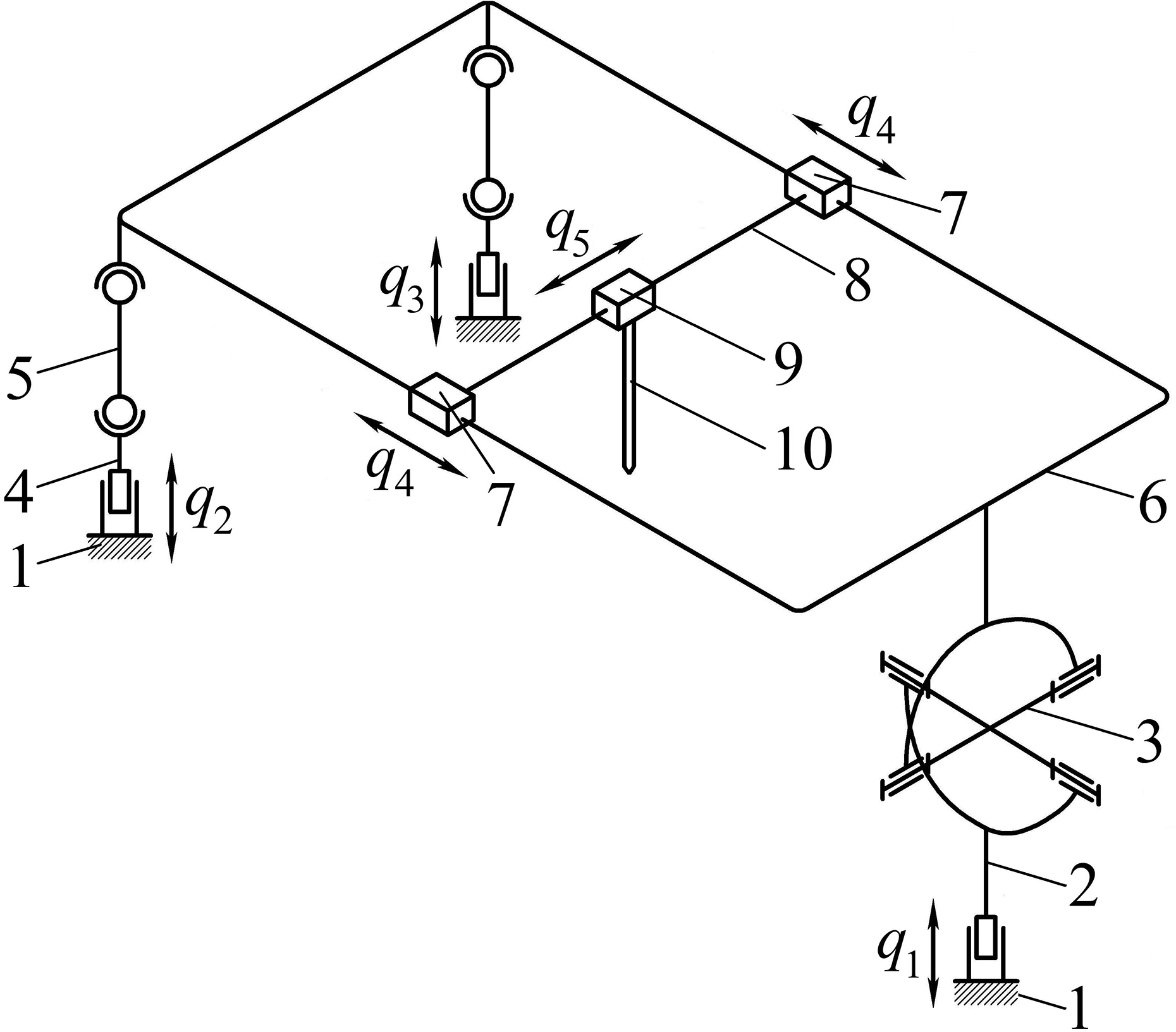
Structural scheme of the 5-DOF (3T2R) parallel–serial (hybrid) manipulator.
Each of the three chains mounted on the fixed link is coupled with movable frame 6, on which a carriage is located, formed by links 7 and 8 rigidly connected to each other. Therein, an additional carriage 9 is coupled with link 8. Thus, both carriages provide displacements in perpendicular directions in the plane of frame 6 and have actuators providing displacements q4 and q5. Output element 10 is mounted on carriage 9, so these two links form the manipulator’s end-effector.
Kinematic pairs 1–2, 1–4, 6–7, and 8–9 are prismatic; pairs 2–3 and 3–6 are rotational; pairs 4–5 and 5–6 are spherical. The manipulator includes a spatial part with parallel structure (links 1–6) and a planar part with serial structure (links 7–9).
Kinematic chain 1–2–3 in the parallel part provides frame 6 with three DOFs due to having the universal joint. The joint imposes three following constraints: the first one is on the rotation of frame 6 around the axis perpendicular to the spider plane, and two others are on the translations in any directions perpendicular to this axis. Therefore, three actuators providing displacements q1, q2, and q3 are required for positioning frame 6 in space. The remaining two chains 1–4–5, located in the parallel part of the manipulator, do not impose any constraints on the movement of frame 6 and the end-effector. A passive mobility appears in each of chains 1–4–5: the rotation of legs 5 around their longitudinal axes. Such mobility does not affect the movement of frame 6 and the end-effector.
The planar part with the serial structure provides the manipulator with two additional DOFs—translational displacements in perpendicular directions in the plane of frame 6, determined by parameters q4 and q5. Thus, the positioning of the end-effector is realized by five actuators providing displacements q1, q2, q3, q4, and q5; 3T2R motion pattern of the end-effector is provided as follows: the parallel part provides one translation and two rotations motion pattern (1T2R) and the serial part provides two translations (2T).
One should note that 3T2R motion pattern can degenerate in singular positions. For example, if the manipulator is in the position where the plane of spider 3 is parallel to the axis of displacement q1, one translational DOF is lost. In this case, displacements q1 and q3 will correspond to the displacement along one coordinate of the end-effector.
The mobility of this manipulator can be verified using structural formulae. The mobility of the parallel part is determined by the following formula for spatial kinematic chains

where W is the mobility of kinematic chains defining its number of DOFs; n is the number of movable links of a kinematic chain; p5, p4, p3, p2, and p1 are the numbers of 1-, 2-, 3-, 4-, and 5-DOF kinematic pairs.
Having parameters n = 7, p5 = 5, and p3 = 4 of the parallel part of the manipulator, it comes from (1) that W = 5. Excluding two passive mobilities of legs 5, three DOFs remain for the parallel part, that is, W = 3.
The mobility of the serial part can be defined by the following formula for planar kinematic chains

Having parameters n = 2 and p5 = 2 of the serial part of the manipulator, it follows from (2) that W = 2. Thus, the overall mobility of the manipulator is determined by summing the results obtained by (1) and (2), and with the exclusion of two mobilities in the parallel part, the overall mobility becomes equal to five.
Based on the structural scheme of the manipulator shown in Figure 1, its detailed CAD model was developed. It is shown in Figure 2. The carriages provide the movement of links along frame 6 in perpendicular directions. Each carriage has two actuators on both sides.

CAD model of the 5-DOF (3T2R) parallel–serial (hybrid) manipulator.
The application of this manipulator can be associated with the manufacture and processing of machine components having complex shapes, as well as mechanical elements, in which the longitudinal dimension exceeds the transverse one. The application of this manipulator can also be associated with performing surgical operations and research procedures.
Kinematic analysis of the manipulator
Consider kinematic analysis of the manipulator, which consists, first of all, in solving inverse and forward position problems. The solution of these problems is in searching the relationships between the coordinates of the end-effector and the controlled movements in the manipulator drives, which are chosen as generalized coordinates. Therein, the inverse problem aims to calculate the generalized coordinates for specified end-effector coordinates, and the forward problem is aimed at determining the position and orientation of the end-effector for specified generalized coordinates.
The position of the end-effector can be described by the Cartesian coordinates of any its points, for example, point S (Figure 3). These coordinates can be represented as vector

Toward kinematic analysis of the 5-DOF (3T2R) parallel–serial (hybrid) manipulator.
Let’s locate coordinate system SXSYSZS at point S of the end-effector in such a way that its ZS axis is directed along the axial axis of output element 10—unit vector
The generalized coordinates of the manipulator can be written as vector

where values q1…q5 correspond to the displacements in actuated kinematic pairs (Figure 3).
Consider next the features of solving inverse and forward kinematic problems for the discussed 5-DOF manipulator.
Inverse kinematics solution
The solution of the inverse problem consists in determining generalized coordinates vector
Let’s attach coordinate system PXPYPZP to frame 6. Its origin, point P, as well as the directions of the axes can be arbitrarily chosen (Figure 3). The orientation of the end-effector relative to frame 6 is kept constant since the movement of the end-effector relative to frame 6 is realized by two prismatic kinematic pairs 6–7 and 8–9. In this regard, the following ratio can be written

where
The components of vector

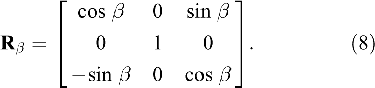
where rotation matrices
Matrix

where

Links movements (rotations) in 2-DOF universal joint.
All the components of matrix
Matrix

Matrix
Matrix

where

Components of vector

where n1x, n1y, n1z and n2x, n2y, n2z are components of vectors
Expression (11) can be used to determine angles α and β. For example, the relationship for calculating angle β can be obtained from the first line of expression (11)

from which

As far as rotation matrices are orthogonal, expression (12) can be rewritten as follows

The expression for calculating angle α can be similarly composed from the second line of expression (14)

from which

Expressions (13) and (16) allow finding the values of angles α and β in universal joint 2–3. The selection of the sign in these expressions is determined by the manipulator’s design. Rotation matrix

where
Parameters

where

where
Parameters

The values of the generalized coordinates q1, q4, and q5 can be found by sequential performing the scalar product of each of the auxiliary values of expression (20) with both sides of relation (18)

Note that the denominator in any of expressions (21) turns to zero if vectors

Then, expressions for coordinates


where
The coordinates of the centers of spherical joints Ai and Ci are related to each other through length LAiCi of link AiCi:

Let’s substitute (23) and (24) in (25) and get quadratic equation relative to qi after transformations

The calculation of coefficients bi and ci is in Appendix 1, formulae (A1) and (A2). In the general case, quadratic equation (26) has two solutions, and the choice of a specific one is determined by the design features of the manipulator. Thus, the values of all five generalized coordinates of the manipulator were determined.
Forward kinematics solution
The solution of the forward position problem for the studied manipulator consists in finding vector

where
Let’s square both sides of expression (27) with respect to expression (5)

Formulae (A3) to (A5) given in Appendix 1 allow to calculate parameters

Coefficients Di, Ei, and Fi depend on angle α and can be found in Appendix 1 (formulae (A6) to (A8)). Let’s apply the tangent half-angle substitution

using which relationship (29) can be written in the following way

Coefficients ki2, ki1, and ki0 are in the Appendix 1, formulae (A9) to (A11). Further, one can apply dialytic elimination method 45 to determine the solutions of equation system (31). For this purpose, firstly multiply both sides of expression (31) by tβ and rewrite the resulting equation system substituting for i = 2 and 3

Equation (32) can be presented in matrix form

where

Relationship (33) is a system of linear equations with respect to vector of unknowns

Substituting (34) in (35), we obtain the following equation

Since coefficients ki2, ki1, and ki0 have the degree of tα not greater than two, relationship (36) is an octic polynomial equation with respect to variable tα. This equation will have eight solutions (including complex ones), which can be found, for example, as the eigenvalues of companion matrix for the polynomial on the left side of expression (36). 46
Variable tβ can be found by multiplying the first equation of system (32) by k32, the third equation by k22, and subtracting them from each other. Finally, the following equation is obtained

After calculation parameters tα and tβ, angles α and β can be found using equation (30), and rotation matrix
Thus, the position and orientation of frame 6 are determined. The further solution of the forward position problem is as follows: coordinates
Reachable workspace construction
Several types of workspaces are known for parallel and parallel–serial manipulators [1]: translation, orientation, reachable, dextrous, and others. This study provides an approach to find a reachable workspace, that is, the set of positions, which the end-effector can take with at least one orientation. For the presented manipulator, the reachable workspace corresponds to the set of all possible values of vector
Let’s consider the following constraints for the presented manipulator, which affect the shape and size of the workspace:
Constraints in actuated kinematic pairs

where
Constraints in angles of universal joint 2–3

where αmin, βmin, αmax, and βmax are the minimal and maximal values of angles α and β.
Constraints in angles ϕ Ai and ϕ Ci in spherical joints 5–6 and 4–5, i = 2, 3

where ϕ Ai min, ϕ Ci min, ϕ Ai max, and ϕ Ci max are the minimal and maximal values of angles ϕ Ai and ϕ Ci .
Angle ϕ
Ai
can be defined as the angle between vector

Angle ϕ
Ci
can be defined as the angle between vectors

To determine the reachable workspace taking into account the above constraints, the previously obtained algorithms for solving the inverse and forward position problems can be used: Given the values of generalized coordinates q1, q2, and q3 from range (38) and using the approach for solving the forward position problem, it is possible to determine the reachable workspace of point P, the center of frame 6. Since there are theoretically up to eight different assemblies of the manipulator for each combination of q1, q2, and q3, the reachable workspace found at this stage can include several disjoint areas. Coordinates q1, q2, and q3 can be specified by discretization of range (38) with any desired step. The values of angles α and β corresponding to each value of The solutions For the remaining values of Since point S has two translational DOFs relative to frame 6, the set of its possible positions relative to point P is a plane. The position and orientation of this plane in space is uniquely determined by parameters
Examples of kinematic problems solution and workspace construction
Consider examples of position problems solution in this section. The geometrical parameters of the manipulator are presented in Table 1, they correspond to the developed CAD model shown in Figure 2.
Manipulator parameters.

The following arrangement of coordinate systems is taken in the considered examples. Global coordinate system OXYZ is set in such a way that its origin, point O, is at the geometric center of the plane corresponding to the upper surface of the base. X and Y axes are in the same plane, and X axis is perpendicular to the long side of the base, and Y axis is perpendicular to the short side. Z axis is perpendicular to the base plane and directed upward vertically. Points Bi, i = 1…3, are in XY plane. The direction of vector
Origin P of coordinate system PXPYPZP is located in the geometric center of the plane corresponding to the top surface of frame 6. XP and YP axes are in the same plane, herewith XP axis is perpendicular to the long side of frame 6, and YP axis is perpendicular to the short side. ZP axis is perpendicular to the plane of frame 6 and is directed upward. Point D is chosen in such a way that it coincides with point P. Vector
Example of inverse kinematics solution
Consider an example of the inverse kinematics solution. Let’s take laws of position


Such law motions correspond to three revolutions in 15 s of point S along a spiral-helical trajectory, the axis of which coincides with Z axis of global coordinate system OXYZ (Figure 5). The radial step of the curve is equal to the axial one and is 30 mm. At the initial time point, the height of point S above XY plane is 240 mm. In this case, the orientation of the end-effector changes in such a way that vector

The motion trajectory of the manipulator’s end-effector for solving the inverse kinematic problem (arrows show the orientation of output element 10).
The solution of the inverse position problem according to the developed algorithm was carried out using MATLAB package. The solution results are shown in Figure 6.
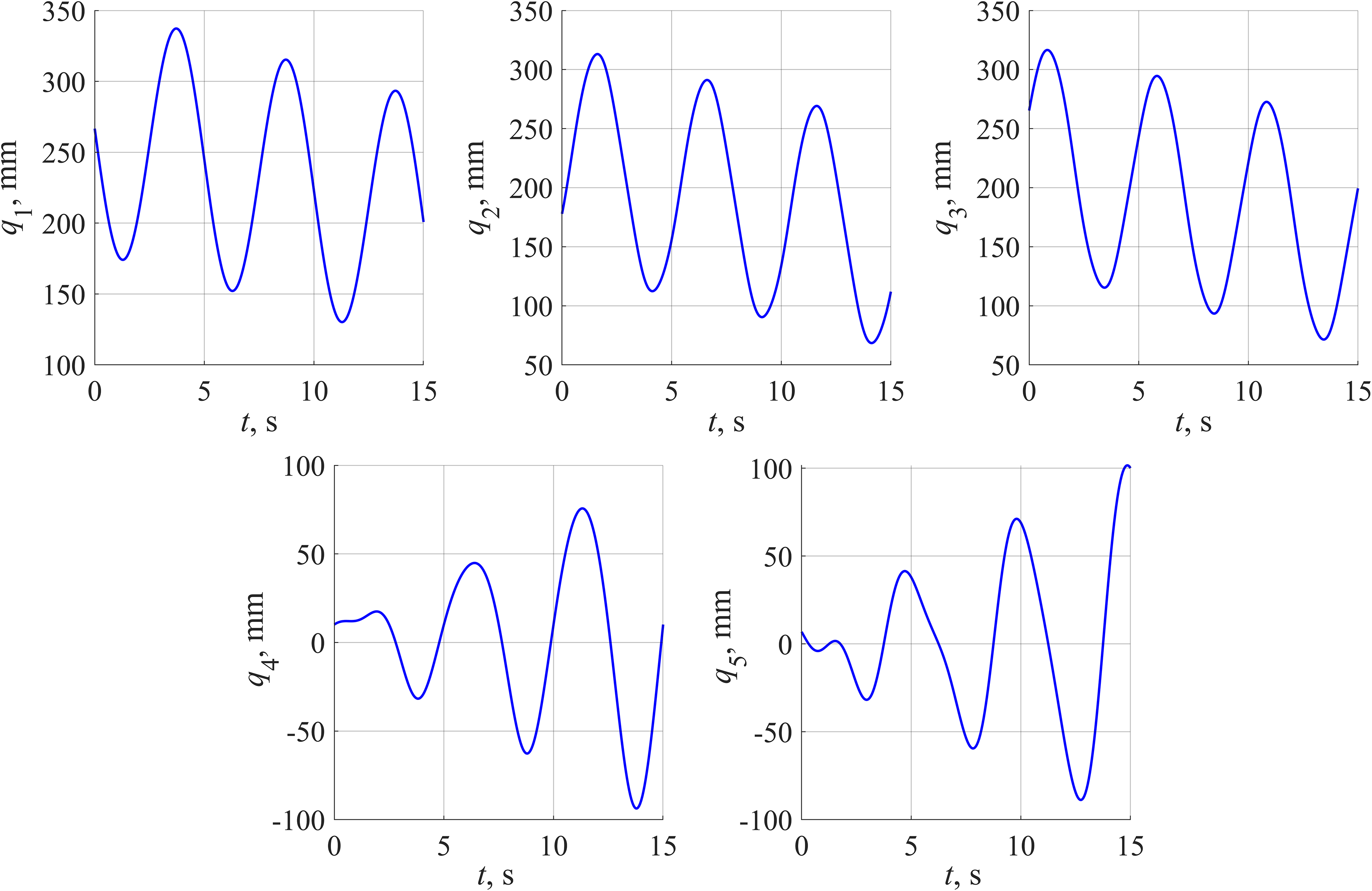
The inverse problem solution when the end-effector moves along the spiral-helical trajectory shown in Figure 5.
It follows from Figure 6 that all five generalized coordinates have an oscillatory nature. Oscillations of generalized coordinates q1 – q3 are caused by the rotation of output element 10 around Z axis, their amplitude is constant, but the entire oscillation range is shifted, which corresponds to the movement of output element 10 along Z axis. The oscillatory amplitude of generalized coordinates q4 and q5 increases, this is due to the spiral motion of point S in the plane parallel to XY plane.
Example of forward kinematics solution
Consider an example of the forward kinematics solution. Suppose that the values of the generalized coordinates correspond to the solution of the inverse position problem for laws (43) for certain random time point. For example, for t = 3.7 s the following values of the end-effector’s coordinates and the corresponding values of the generalized coordinates (accurate to two decimals) are obtained


The solution of the forward position problem for the values of the generalized coordinates given in (46) was carried out according to the developed algorithm using MATLAB package. Polynomial equation (36) was obtained using symbolic calculations. The solution of this equation was determined using standard function “vpasolve.” Solution of equation (36) gave eight values of variable tα, four of which were complex. Further calculations were carried out only for the real values of the variables. Consequently, four groups of values of vectors
Solution of the forward kinematic problem.a
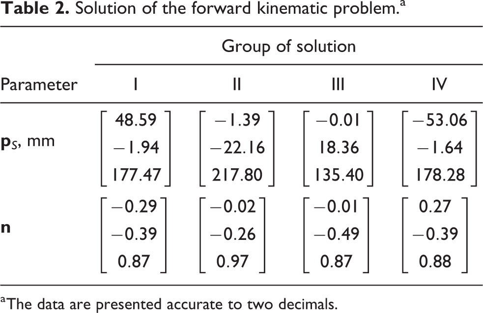
a The data are presented accurate to two decimals.
Group of solution II according to Table 2 corresponds to expressions (45). Groups of solution I, III, and IV refer to three other configurations of the manipulator that exist for the same values of the generalized coordinates given in (46). Figure 7 shows the assemblies of the manipulator corresponding to the obtained solutions of the forward position problem given in Table 2.

Assemblies of the 5-DOF (3T2R) parallel–serial (hybrid) manipulator obtained in solving forward kinematic problem: (a) to (d) correspond to groups of solutions I to IV presented in Table 2.
Example of reachable workspace construction
Let’s consider an example of reachable workspace construction. Constraint values (38) to (40) correspond to the CAD model of the manipulator shown in Figure 2 and are presented below

Unit vector that is perpendicular to the plane of frame 6 (the third column of matrix
First, the reachable workspace for point P was determined according to the presented methodology. Calculations were carried out for 10 values of each of coordinates q1, q2, and q3 (1000 different combinations in total), equally distributed within range [

The reachable workspace for point P: conditions (39) and (40) are not satisfied in the red and green areas; the blue area satisfies all the requirements.
Condition (39) excludes some of the solutions (red areas according to Figure 8), and condition (40) leaves only one feasible solution range (blue area according to Figure 8).
Next, the reachable workspace for point S was determined as a set of planes (Figure 9). The dimensions of the workspace and the extreme values of angles α and β (which describe the orientation of the manipulator’s end-effector for a given geometry of links) are given in Table 3. Comparing the dimensions of the two workspaces according to Figures 8 and 9, it is easy to conclude how the use of parallel–serial structure greatly increases the size of the workspace.
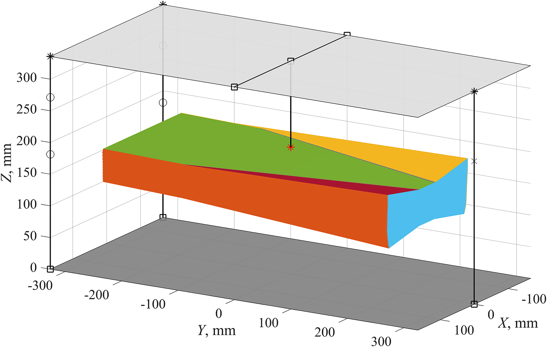
The reachable workspace of the manipulator.
Dimensions of the reachable workspace and extreme values of the orientation angles.a

a The data are presented accurate to two decimals.
Conclusions
Algorithms for solving the inverse and forward position problems and also approach of reachable workspace construction for the 5-DOF parallel–serial (hybrid) manipulator, in which the end-effector has three translational and two rotational DOFs (3T2R motion pattern), are obtained in the present study. The considered manipulator includes a parallel part with three DOFs (1T2R motion pattern) based on a tripod and a serial part with two DOFs (2T motion pattern) based on two carriages displaced in perpendicular directions. This manipulator can find application in solving a wide range of technological problems. In particular, it can be used for processing elements having complex shapes and elements in which the size of one dimension exceeds the size of another.
The kinematic analysis results show that the solution of both inverse and forward position problems can be obtained in an analytical form. When solving the inverse problem, first, the rotation angles in the universal joint are determined based on the given orientation of the end-effector, then the generalized coordinates are calculated. In this case, the existence of several solutions is possible, where the choice of a specific solution is determined by the design features of the manipulator. The solution of the forward position problem is based on the application of dialytic elimination method. Using this method, the solution comes to finding the octic polynomial equation roots. It corresponds to the theoretical existence of eight different configurations of the manipulator for the same values of the generalized coordinates.
An approach to find a reachable workspace for this manipulator was developed based on the proposed algorithms of solving both position problems. This approach takes into account the constraints imposed on the generalized coordinates and on the allowable angles in the universal and spherical joints. First, the reachable workspace is calculated for the parallel part of the manipulator and then for the entire manipulator as a whole system. Examples of calculations using MATLAB package are given for all the proposed approaches.
An example of inverse problem solution corresponded to the movement of the end-effector along a spiral-helical trajectory. The laws of generalized coordinates variation, which are necessary for the realization of the given type of movement, are determined in the results of calculation. An example of forward problem solution is considered for the case when four different assemblies of the manipulator exist at the same given values of the generalized coordinates.
For the given geometry of the manipulator and the prescribed values of the design constraints, the reachable workspace was built. Its shape, dimensions, and also the extreme values of the end-effector orientation angles were determined. The kinematic analysis of the manipulator performed in this study can serve as a basis for the further analysis of velocities and accelerations. In addition, the singularities that can affect the shape and size of the workspace of the manipulator are of special interest. The determination of such positions is related to the velocity analysis of the manipulator and is the subject of upcoming research.
Footnotes
Declaration of conflicting interests
The author(s) declared no potential conflicts of interest with respect to the research, authorship, and/or publication of this article.
Funding
The author(s) disclosed receipt of the following financial support for the research, authorship, and/or publication of this article: The study was supported by the Russian President Grant according to the research project MK-2781.2019.