
Abstract
Jumping capability of humanoid robots can be considered as one of the cruxes to improve the performance of future humanoid robot applications. This paper presents an optimization method on a three-linkage system to achieve a jumping behavior, which is followed by the clarification of the mathematical modeling and motor-joint model with practical factors considered. In consideration of the constraints of ZMP and the performance of the motor, the output power of the joint motors is maximized as much as possible to achieve a higher height. Finally, the optimization method is verified by the simulation and experiment. Different from other electric driven robots, which take the output power of the joint as the constraint, we maximize the output power of the joint to optimize the hopping performance of the robot. Realizing dynamic jumping of humanoid robots can also provide a solid foundation for further research on running, which can greatly enhance the environmental adaptability.
Introduction
In the past few decades, the research of humanoid robots has made breakthroughs in stable walking and dexterous operation.1–6 Lacking of diversified motion mode, humanoid robots are not qualified for operating in intricate occasion. For instance, without jumping ability, the robot will not able to pass through the discontinuous road. As for the aspect of the jumping motion, humanoid robots are still lagging behind, while jumping is one of the basic locomotion abilities of human beings. By means of jumping, human beings can avoid obstacles and adapt to discontinuous complex terrain promptly. Analogously, humanoid robots capable of jumping ability as human beings will greatly improve their adaptability to complex environments, thereby further promoting humanoid robots’ practical process. Hence, researchers have focused their interest intensely on multifarious jump in recent years.7–10
Many research works devoted to jumping robots have been reported. Some of them used hydraulic driving or pneumatic driving to enhance the actuating force of the robot. Raibert’s team from MIT studied hopping with hydraulically driven leg robots. 11 Based on the former, the Atlas robot developed by Boston Dynamics is capable of many motion tasks.12,13 Hosoda from Osaka University developed a lower limb jumping mechanism composed of pneumatic bionic muscles. 14 Although hydraulic driving and pneumatic driving offer some advantages, there are still some issues to deal with. The hydraulic system is relatively complicated and heavy, which may cause hydraulic oil leakage accidents. 15 Moreover, the sensitivity to oil temperature makes it a challenge to control stability. The drawbacks of the latter, pneumatic driving, are the low transmission efficiency and high noise.
Part of researches investigated the method by installing elastic energy storage elements to pre-store energy for jumping. Niiyama et al. 16 added springs to the legs of the Mowgli robot as elastic links to achieve a jump of more than twice its own height in 2007. Curran and Orin 17 and Ugurluet al. 18 focused on the jumping mechanism with spring and other energy storage elements and its control strategy. These researches are to improve the jumping performance of robot through bionic mechanical design. Elastic element has merits in terms of energy storage and release, while it also brings certain limitations to other motion tasks.
Some research realized jumping by strengthening hardware. Okada and Takeda 19 developed a design method of nonlinear profile of gear ratio to utilize a DC servo motor effectively for a jumping robot. The HRP3L-JSK humanoid robot developed by Tokyo University in Japan enhanced the joint driving ability by means of forced cooling of the motor to achieve jumping. Kojima et al. 20 proposes a design method for achieving a balance between impact mitigation performance and force control fidelity. They mainly improve the high impact mitigation and force control ability of the robot by optimizing the structure design. In the aspect of hardware design and enhancement, these works can provide some inspiration. These methods that specialized hardware designs are difficult to replicate directly with other humanoid robots.
Other research used the method of planning the trajectory for the humanoid robot to jump. Victor et al. 21 presented a control method for planar vertical jump in 2005, which imposes the trajectory following for the distance between the foot and the total center of mass and maintains the CoM above the feet during the whole jump. Sakka and Yokoi 22 dealt with the generation of motion pattern for humanoid robots’ vertical jump in 2006. The study concentrates on the landing phase of the jump, assuming the characteristics of the aerial phase are known. Based on previous work, they proposed a method 23 for adapting human vertical jumping dynamics to humanoid robotic structure using precomputed reference trajectory. Taking the ground reaction force (GRF) as the model reference and bodies inertial forces as task constraints while optimizing energy to determine the humanoid robot posture and improve its jumping performance. Hong 24 realized vertical jump on the Darwin-OP simulation model through CPG and evolutionary optimization. However, it is difficult to apply the method of small-scale robot directly to large-scale humanoid robot platform. Cho and Oh 25 and Cho et al. 26 from Kaist University designed PD position controller and attitude balance controller to realize the jumping of HUBO2 robot by planning the trajectory of the robot’s feet. In this way, HUBO2 can resist large disturbance in the jumping process, but the jumping height is not obvious. Most of the above methods only take the output power of the joint as the constraint, and we maximize the output power of the joint to optimize the jumping performance of the robot.
Their work has certain significance for the research of modeling and control of jumping motion of humanoid robots, but the issue of motor output is not considered. In this paper, we will aim to maximize the output of the motor, while ensuring the stability of the take-off process to achieve effective jumping. For the process of jump, the critical part that needs to be controlled is the trajectory of the robots in the take-off phase and the initial velocity of the flight phase, while the latter is crucial to determine the maximal height that robot can reach. Certainly, the output power of the actuators is roughly proportional to the maximal height when the energy consumption rate is constant. In summary, a coordinated take-off is extremely vital for the whole jumping process.
In our previous work, 27 we proposed a jumping planning method for robot with ideal motor model and did some simple simulation of vertical jump. Based on the previous work, this paper makes a more accurate model between the motors and the joints, rather than the ideal model previously assumed. In this paper, we simplify the BHR-6 humanoid model and obtain the simplified structure. On this basis, the kinematics and dynamics of the mathematical model and the joint model are illustrated. In terms of the aspect of planning trajectory, starting from the joint space, multiple joints are allowed to work together with the maximum torque allowed by the motor to achieve an effective vertical jump. Meanwhile, taking account of the constraint of ZMP point (zero moment point) on the soles of robot’s feet, the joint torque of robot is fine-tuned to ensure the dynamic stability of robot during take-off phase and achieve joint coordination. Experiment results are proposed to prove the effectiveness of the trajectory. From our perspective, this study is interesting for the modeling and trajectory planning of the humanoid robot vertical jump.
The remainder of this paper is organized as follows. In Section 2, we present reasonable assumptions and construct suitable simplified structure for the vertical jump of the humanoid, followed by the mathematical modeling and the joint model which considers the reducer efficiency, joint friction, and damping. Considering the constraints in hardware and physical, the trajectory planning method to realize vertical jump is clarified in Section 3. We verify the validity of the proposed method in the experiment in Section 4. Finally, conclusions and perspectives are addressed in Section 5.
Modeling
In this section, we first make some assumptions for the vertical jump of humanoid robot and further simplify the BHR-6 robot’s structure for our analysis. (BHR-6 is the sixth generation of Beijing Institute of Technology Humanoid Robots.) Then, the mathematical model and the motor model in consideration of factors of reducer efficiency, joint friction, and damping are illustrated.
Assumptions and Simplified structure
For better modeling of the vertical jump of the humanoid robot, this paper puts forward several reasonable assumptions as follows:
(AS1) The whole vertical jump process is completed in one plane.
(AS2) The robot is completely symmetric with respect to the sagittal plane.
(AS3) In the take-off phase, there is no slipping between the robot’s feet and the ground. (This is satisfied when the ground friction constraint and ZMP constraint are satisfied, which will be discussed in detail later.)
(AS4) Each joint is individually driven by a motor.
According to AS1-2, the BHR-6 model can be simplified to the sagittal plane model. Thus, as shown in Figure 1, the simplified structure of an open-loop kinematic chain composed of four links and three joints are obtained.

(a) BHR-6 humanoid robot, (b) BHR-6 model, and (c) simplified structure: the three-linkage inverted pendulum of the take-off phase.
Mathematical modeling
In the take-off phase of the vertical jump of the robot, since there is no relative movement between the foot and the ground, the simplified model of jump movement in Figure 1 can be further simplified to a three-linkage inverted pendulum fixed on the ground.
As shown in Figure 1, the origin of the world coordinate system
According to the Lagrange equation, the dynamic equation of the take-off phase is expressed as equation (1):

Where

Due to the factors of reducer efficiency, joint friction, and damping, the relationship between joint end torque and motor end torque is not simply multiplied by the deceleration ratio. After precise modeling of the motor model, the relationship between the motor torque and the joint torque is obtained as shown in equation (3).

Where
To determine the time of the robot leaving the ground, it is necessary to calculate the acceleration of the CoM of the robot in the vertical direction. When it is equal to
From Figure 1, the position of the CoM of the robot in the take-off phase can be calculated as

Method
In the take-off phase, the CoM of the humanoid robot is expected to be accelerated by high torque of the joints, and at the same time obtains a high initial speed for the flight phase.
In this section, based on the three-linkage inverted pendulum model of the take-off phase proposed in Section 2, the motor at the joints can do work sufficiently as far as possible to achieve stable and efficient vertical jump under the conditions of robot ZMP constraints and others.
Constraints
Ground friction constraint
We have presented the assumption that there is no slipping between the foot and the ground (AS3). The premise of this assumption is that the physical constraints of ground friction need to be met, that is, the force applied to the soles of the foot must meet the constraints of the ground friction cone. Supposing the friction coefficient of the ground is

Motor constraint
Like most humanoid robots,
28
BHR-6 is equipped with the same Parker motor(K044100-6Y-4.98Ams) in the ankle, knee, and hip joint. In the take-off phase, with the increase of the joint speed, the torque provided by the motor to the joints is constrained by the motor properties, which means that the sustained torque and peak torque provided by the motor at a certain speed are limited. Since the robot takes off in a very short time, only
According to the motor manual, the function relationship between the peak torque of the motor and the speed can be established, and the value of the peak torque


Motor properties curve.
Neglecting the factors of reducer efficiency, joint friction, and damping, if the reducer with a deceleration ratio of

According to equation (3), the torque

ZMP constraint
In order to ensure that the soles of the robot remain relatively fixed with the ground during the take-off process, the ZMP range of the robot should be limited to prevent the soles from overturning. The position of ZMP

In the high-speed motion mode, the ZMP point of the robot may be close to the edge of the sole of the foot, which may cause the robot to be prone to toppling. For the sake of the dynamic stability of the robot in the take-off phase, the position of ZMP of the humanoid robot needs to be constrained. Figure 3 is the top view of the robot, point

Where Δpx is the stability margin constant of ZMP.

ZMP constraint.
Trajectory planning strategy
As mentioned in Section 2, in take-off phase, the CoM of the robot accelerates rapidly until the acceleration equals g in the vertical direction, which means the robot enters flight phase. On account of the fixed third-order inverted pendulum model, the robot can’t leave the ground. When the robot has a tendency to leave the ground, it will be pulled downward by the ground. Therefore, the jump determination condition of the robot is equation (11).

From the velocity

The position of ZMP can be expressed as a function of joint angular acceleration

When the current ZMP exceeds the constraint, it can be changed by joint angular acceleration

For greater energy output from each joint of the robot in the take-off phase, maximal torque will be provided to each joint as much as possible under every constraint. The relationship between the variation of joint torque

Due to the motor constraint, the variation of joint torque

Where
Since

As shown in the control flow chart in Figure 4, the optimal adjustment of the angular acceleration of joints will be calculated to minimize the cost function (17) and satisfy the ZMP constraint equation (14) and motor constraint equation (15) at the same time.

Take-off control flow chart.
Experiments and results
With the three constrains described in the previous section, the trajectory of the take-off phase is obtained using maximized joint power. To verify the effectiveness of the vertical jump trajectory of humanoid robot proposed in this paper, verification needs to be carried out through the simulation and experiment. Due to the dozens of DOF (Degree of Freedoms) and multiple sensors of the humanoid robot, which are expensive to manufacture and difficult to maintain, in this section, we firstly use a combination of MATLAB and V-rep dynamics simulation software for simulation. Then, we do confirmatory experiment on a simple three-link platform.
In the simulation, when the motor model is assumed as ideal, the BHR-6 model can jump on a vertical barrier of 0.6 m. In consideration of reducer efficiency, joint friction and damping factors, the precision motor-joint model is adopted according to equation (3). As a result, the robot can jump on a 0.2 m high platform. After that, a simple jump experimental platform is designed and made for preliminary experiment with a control system based on the EtherCAT bus. Then, in the experiment, the effectiveness of the motion coordination strategy proposed is verified.
Simulation
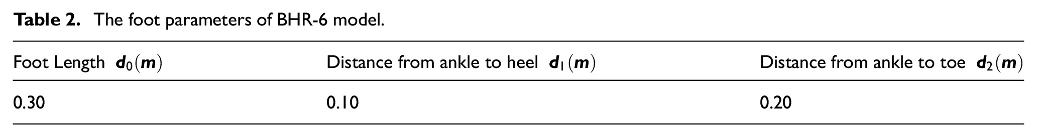
In this section, MATLAB and V-rep are adopted to establish the dynamic simulation environment. The controller is written in MATLAB in terms of the control flow chart in Figure 4. Considering the simplified model of jump movement model in Figure 1, the BHR-6 model is built in V-rep. The dynamic parameters of simplified BHR-6 model are set as shown in Table 1. In addition, the foot parameters of BHR-6 model are shown in Table 2. Every period, MATLAB Controller sends a set of joint control parameters to V-rep for real-time simulation, and gets the joint state parameters returned.
The dynamic parameters of simplified BHR-6 model.

The foot parameters of BHR-6 model.
The BHR-6 model is transformed from a standing upright position to a squat initial take-off posture through the PVT interpolation. According to the control flow chart that we mentioned before, the motion trajectory of the model of every period can be obtained.
As shown in Figure 5, ignoring the factors of reducer efficiency, joint friction, and damping, the robot can jump onto a

Simulation of BHR-6 model: (a) jumping onto a 0.6 m step and (b) jumping onto a 0.2 m step.
The joints angle curve of the simulation during the take-off phase of the jump is shown in Figure 6, and the velocity change of the CoM is shown in Figure 7. Among them, “ideal” refers to the ideal motor-joint model; “precise” refers to the precise motor-joint model. In both figures, the curves overlap in the first

Joint angle curve of the simulation before landing.
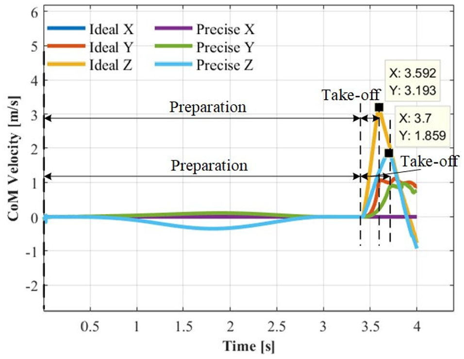
CoM velocity before landing in simulation.
It can be inferred from Figure 7 that when the ideal motor model is adopted, the robot’s velocity at the take-off time is
In the simulation, joint velocity of the take-off phase increases monotonously, and the curve is shown in Figure 8. At the same time, the curve of joint torque versus the joint velocity in this phase is shown in Figure 9, which is directly connected to the motor characteristics. Along the direction of speed change, the area enclosed by the torque curve and the horizontal coordinate axis of the joint velocity is the output power by the motor. It can be clearly seen that the surrounding area of the curve corresponding to the ideal motor model is larger than that of the precise motor model, which means the output power of the ideal motor model during the take-off phase is obviously greater than that of the precise motor model. This is mainly attributed to the different actual loss of the precise motor model.

Joint velocity in the take-off phase of the simulation.

Joint torque versus joint velocity in the take-off phase of the simulation.
In this process, the output power of the precise motor-joint model is smaller than ideal model, which is confirmed by the Figure 9. Owing to this, the robot takes a longer time to take off, which is confirmed by the Figure 6. On the other hand, the maximum vertical velocity of the CoM is also smaller, which is confirmed by the Figure 7. For the same reason, the joint angle of precise model changes less than the ideal model, which is confirmed by the Figure 8.
Experiment
The experiment of the vertical jump is carried out on a simple jump experimental platform, which was built in terms of BHR-6 simplified structure. The mechanical structure drawing of it is shown in Figure 10. Parker motors K044100-6Y with reduction ratio of 100 is installed in each joint. To enhance the structural strength of the robot, structural reinforcement parts are added between the left and right leg plates. Meanwhile, the arc design on the leg board improves the motion range of joints. The parameter of the simple humanoid robot jump experimental platform is shown in Table 3.

The mechanical structure drawing of the simple jump experimental platform.
The specific parameters of jump experimental platform.

The control system needs to coordinate multiple motors to work together. At the same time, in order to ensure that the trajectory executed by the joint meets the desired dynamic characteristics, the control period needs to be as short as possible. Therefore, the EtherCAT bus network is adopted on the simple experiment platform for jumping motion, and the Platinum Maestro multi-axis controller is used as the master station to convert the control instructions into joint control instructions and send them to each Gold Twitter drive. Adopting distributed control system, the driver itself controls the position loop, speed loop, and current loop, and returns the sensor information requested by the multi-axis controller for further transmission to the PC for motion control and planning. In the end, the system achieved a control period of 1 ms with a period error
Based on the simple jump experiment platform of humanoid robot, the take-off trajectory of the robot is optimized in light of control flow chart in Figure 4.
Figure 11 shows the whole process of the robot jumping. In the experiment, the robot first moves to the initial state of the take-off phase by PVT interpolation. Figure 11 (1) shows the initial state. Then the robot follows the planned joint trajectory to achieve the vertical jump. In Figure 11 (4), the robot is about to leave the ground. After that, the robot enters to the air. From Figure 11(6), it can be seen the robot eventually reach the height of about 0.16 m (in the experiment, the projection point of the ankle on the sole of the foot is used as the measurement point of the height of the robot). The whole process takes 0.246 s. Figure 12 shows the changes of joint angles during the whole process. The “desired” curve is the planned trajectory, while the “actual” is obtained from real experiments. The two curves are roughly consistent. It can be inferred from Figures 11 and 12 that the initial hip angle of the robot is relatively large, so the hip can do work sufficiently to help the robot off the ground. The experimental results are shown in Table 4. In the process of vertical jump, the error between the actual and expected angles of the three joints is small, so the height is only 0.016 m lower than the simulation value, which shows the effectiveness of the planned trajectory of humanoid robot proposed in this paper.

Vertical jump experiment.
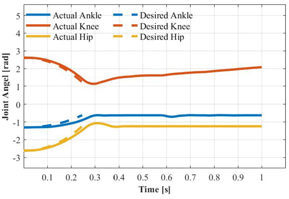
Actual angle and desired angle of joints.
The experiment results of vertical jump.

Conclusion
Humanoid robot has important scientific research significance and practical value. However, the weak adaptability to complex environment restricts the practical process of humanoid robot. Currently, most rigid humanoid robots driven by electricity are difficult to achieve natural and effective jump, which makes them cannot adapt to complex environments such as ditches and platforms. Therefore, this paper presents a trajectory planning approach to make humanoid robot perform vertical jump.
Firstly, a dynamic model of third-order inverted pendulum is established based on the BHR-6 model. Considering factors of reducer efficiency, joint friction and damping, a precise joint model is built. Then, with three constraints for the jump motion put forwarded, the cost function for maximizing the power output of joints is developed. Finally, our planned trajectory is validated on simulation and experiment. From the results that the robot takes 0.246 s to reach a height of 0.16 m in the experiment, we can infer that it is beneficial to consider the joint model for precise motion results in dynamic jumping.
The contributions of this paper are summarized as follows:
Considering factors of reducer efficiency, joint friction and damping, a precise joint model for the humanoid jumping is developed.
Combined with physical constraints, motor constraints, and ZMP constraints, a planning strategy to maximize the joint power during the jump is proposed.
A simple experimental platform for humanoid robot jumping is designed and made, in which the method proposed in this paper is verified.
In the future, we will consider of the whole-body dynamics to implement the algorithm for bipedal robot and validate the theory on BHR-6 robot. In addition, we will also try to develop the algorithm of continuous jumping motion, which would be preliminary research for the development of robot’s running.
Footnotes
Appendix
Handling Editor: James Baldwin
Declaration of conflicting interests
The author(s) declared no potential conflicts of interest with respect to the research, authorship, and/or publication of this article.
Funding
The author(s) disclosed receipt of the following financial support for the research, authorship, and/or publication of this article: This work was supported in part by the National Key R&D Program of China under Grant 2018YFE0126200 and the National Natural Science Foundation of China under Grant 91748202 and 62073041.