
Abstract
Robot soccer has become an effective benchmarking problem for robotics research as it requires many aspects of robotics including perception, self localization, motion planning and distributed coordination to work in uncertain and adversarial environments. Especially with humanoid robots that lack inherent stability, a capable and robust motion controller is crucial for generating walking and kicking motions without losing balance. In this paper, we describe the details of a motion controller to control a team of humanoid soccer robots, which consists of a hierarchy of controllers with different time frames and abstraction levels. A low level controller governs the real time control of each joint angle, either using target joint angles or target endpoint transforms. A mid-level controller handles bipedal locomotion and balancing of the robot. A high level controller decides the long term behavior of the robot, and finally the team level controller coordinates the behavior of a group of robots by means of asynchronous communication between the robots. The suggested motion system has been successfully used by many humanoid robot teams at the RoboCup international robot soccer competitions, which has awarded us five successful championships in a row.
1. Introduction
The RoboCup federation aims to foster development of an autonomous humanoid robot soccer team that can defeat the reigning FIFA World Cup human soccer team in 2050. Although no robotic soccer team is able to compete against humans yet, this high goal fuels advancements in a wide range of robotic researches. Recently, the DARPA Robotics Challenge (DRC) has provided more impetus to bipedal development, showing how relevant the soccer playing advancements in humanoids can impact outside domains.
Building a soccer playing humanoid robot is still a very challenging task, even with current rules that specify rigid requirements on field surfaces, number of players, and field sizes due in part to the tremendous difficulty of motion planning and execution for bipedal robots. Additionally, with a multi-agent system of two competing teams, there are unforeseen disturbances in the form of robot-robot collisions that force development of robust systems that can operate in a wide variety of conditions. The focus of this paper is to present our attempts to provide a motion controller that not only works for the terrain in RoboCup, but can cope with many disturbances in the environment, and allocate responsibilities among team members to mitigate risks.
Although there have been a number of general purpose open source robotics stacks that support humanoid robot platforms [1, 2, 3, 4], they only provide generic robotics functions so it takes a considerable effort to build a competitive soccer playing system based on them. Recently, a number of robotic soccer teams have released their software as open source [5, 6, 7], most notably the B-Human code which has been universally adopted among Standard Platform League teams [8]. However, most of those open source code releases are only designed to work with Nao[9] humanoid robot, which makes it hard to use on other humanoid platforms.
Our open source motion controller has been developed through years of competition using both DARwIn series[10] and Nao small robot platforms, as well as DARwIn-XOS, CHARLI[11] and THOR series[12] larger sized platforms. Our software is designed to be highly portable, so that it can be easily migrated to a wide range of humanoid robot platform with minimal effort. Due to the requirement to perform various tasks at different level of abstraction and time scale, we adopt a hierarchical structure [13], but to minimize development load for different platforms, we also pursue modularity and portability. The code is composed of a layered set of interchangeable modules, which enables quick adaptation to different hardware platform or different high level task with minimal amount of work. And as we mainly use a simple script language that does not require frequent recompiling, our controller has good readability and requires less development efforts.
The rest of the paper is organized as follows: Section 2 gives a brief description of our cross-platform humanoid robotics software platform. Section 3 presents the low level controller that controls each joint of the robot at every time step, which can use either raw joint angles, a sequence of whole body joint angles or target transforms of the torso and each limb using inverse kinematics solver. Section 4 gives details of the mid level controller, which governs bipedal locomotion of the robot using multiple sub controllers. Section 5 explains the high level controller that handles behavior of each robot, such as moving to the defending position or approaching the ball. Section 6 covers the distributed control of a team of robots using asynchronous communications between the robots. Section 7 briefly introduces how the perception subsystem works, and Section 8 presents the way to optimize each level of controllers using data from both simulated and real robots. Finally, Section 9 concludes with possible future directions.
2. Modular Humanoid Robotics Software Platform
Supporting several humanoid robots that can play soccer in many different leagues can be a challenging task; the similarities in morphology can still lead to vastly different interfaces to the underlying hardware. To exploit the commonalities of different platforms and tasks, and to reduce development time, we introduced a flexible cross-robot software architecture. This architecture aims to incorporate modularity and portability. Every component of this architecture remains individually interchangeable to allow for code sharing between robots. The interchangeable components communicate over a standard interface, requiring a minimal number of platform-specific wrappers.
2.1. Software Architecture
Our software is written in a combination of Lua and C/C++ languages. For ease of development and maintenance we use the Lua scripting language for most of our code. Only those parts that require fast computation or direct hardware access are written in C/C++. For external monitoring and debugging, we use the MATLAB environment. The overall structure of our software architecture is shown in Figure 2. Its main component, the motion subsystem, can be divided into four levels of hierarchy: the low level handles real time control of joints, the mid level governs the bipedal locomotion of the robot, the high level makes task level decisions, and finally the team level coordinates behaviors of multiple robots using asynchronous communication between robots. We can also group the high and team level controllers as behavioral logic. The other component is the perception subsystem, which processes sensory data to observe the environment and localize the robot.
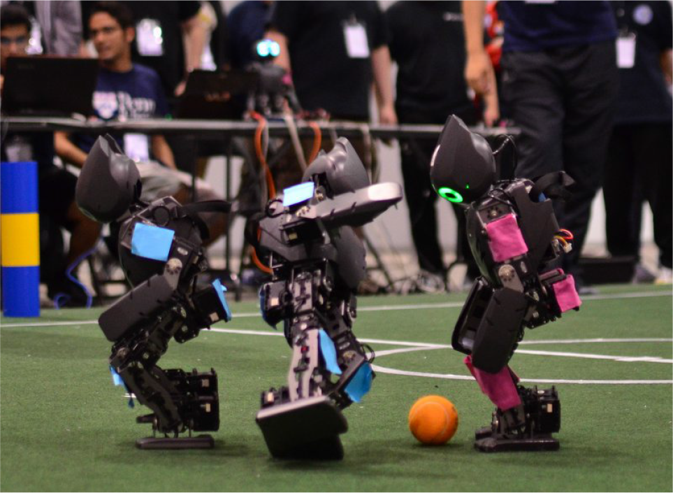
Two teams of DARwIn-OP mini humanoid robots playing against each other at the RoboCup 2012 international robotic soccer competition

The overall structure of the software platform
2.2. Communication Methods
Our software is composed of many functioning modules that have to communicate with other modules in an efficient way. We cannot run every module sequentially, as different modules may have different update frequencies due to the hardware and processing constraints. Furthermore, some robots have two or more onboard computers to distribute their workloads.
Thus, we provide two different methods of local communication between controller modules. The first one includes Boost 1 managed shared memory segments that are accessible by all the modules, which handle all low, medium and high level motion controller signals. This means that separate processes can asynchronously control the motor commands and request motor information without any special broker, nor resorting to running large motion process.
The second means of communication includes ZeroMQ 2 channels. Any data structures can be serialized using the MessagePack specification, and can be directed either locally or remotely to other processes, or remote operator for debugging. This communication method is needed when a secondary onboard computer is used for more sophisticated perception subsystems, or during the testing phase when the human operator needs a large volume of debug data from the robot. Although all the robots we have used for the RoboCup competition have a single onboard computer and are completely autonomous during the matches, the DRC competition required semi-autonomous teleoperation with a large perception load, where we used ZeroMQ channels to coordinate multiple onboard computers and to feed perception data to the remote operator.
During the competition, a team of robots should communicate to make coordinated team behaviors crucial for the match. Although current RoboCup rules allow for visual and auditory communications, they are usually noisy under game situations so most communication is done by the provided WiFi network. To prevent network clogging with many robots, only a very small amount of bandwidth is allowed. Each robot broadcasts a UDP packet every second, which contains teamplay related informations such as current perceived location, last seen ball position, role in the team and target location to move to. To help monitoring and debugging the gameplay, we also include a low resolution, color-segmented vision data which is compressed using run length encoding.
2.3. Hardware Support
Our software platform is designed to support a wide range of humanoid robot platforms, some of which are shown in Figure 3. Currently, the motion controller requires a humanoid robot that can be controlled by target joint angles. This includes robots with distributed modular actuators, where each actuator has own PID controller to control each joint with high frequency current control, and robots with a central microcontroller that handles feedback control for all the joints. For both cases, we run a hardware interface module that periodically publishes target joint angle positions either to the shared communication bus or the microcontroller, and reads the sensory readings from sensors. We provide the hardware interface module for two widely used systems, the Nao humanoid robot and the Dynamixel servomotor systems. Other hardware can be easily supported by adding a new hardware interface module.
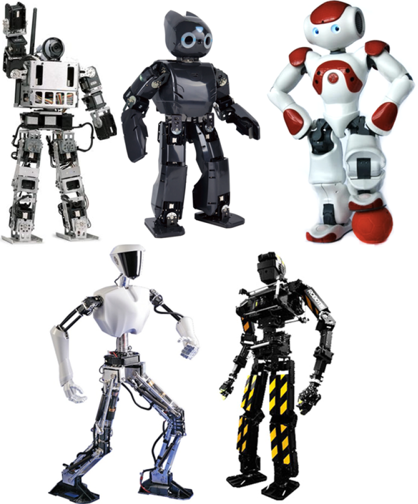
Some of the Supported Hardware Platforms
We also provide support for different hardware configurations of the robot. Although most humanoid robots share the standard 6 DOF leg design with three intersecting hip joints, one knee joint and two intersecting ankle joints, they can have different configurations, such as the Nao robot with shared hip yaw joints. We keep the forward and inverse kinematics solvers as modules, and provide both the standard 6 DOF legs and Nao leg kinematics modules. A new humanoid robot with standard 6DOF leg can be quickly ported after calibrating a few kinematic and dynamic parameters.
Finally, as the RoboCup rule requires onboard computation and sensing for the humanoid leagues, the software should be well optimized to run flawlessly on constrained robots' onboard computers. With the DARwIn-OP robot with a single core Atom processor and single camera, the whole motion and perception processes occupy roughly 50 percent of total CPU usage, where the motion subsystem runs at 100 Hz and the perception subsystem at 30 Hz. With the Nao robot with a similar processor but two cameras, the motion and two vision processes occupy roughly 80 percent of total CPU usage.
2.4. Simulation Support
It is extremely hard to develop an autonomous robot system without first prototyping and testing every component in a simulated environment. Instead of using a soccer specific simulator [14], our software platform can be used with any robotic simulator with the right interface module, and currently it supports the Webots commercial robotics simulator [15] and the Gazebo open source robotics simulation software [16] for a single humanoid robot. With the Webots simulator, the simulation of multiple teams of humanoid robots is also supported. Both of the simulators provide the testing of the perception subsystem using simulated cameras, that can be turned off and substituted with ground truth values with additional noise to speed up the testing.
3. Low Level Motion Control
The low level controller directly communicates with robot hardware, and it runs as a separate process from other modules so that it can run at highest frequency possible. This prevents the robot from possibly jerky or unstable motions even when other part of the system sustains heavy processing load.
To communicate with other modules with possibly different running frequencies, we use the shared memory framework. The low level motion controller maintains memory blocks for motor data and sensory data. At every timestep the low level controller reads current sensory readings such as joint encoder values and inertial sensor values and write them to the sensory data block, and reads command variables from the motor data block and sends them to actuators.
3.1. Joint Level Control
The most basic way to control the robot is through direct joint level control, which can be done by accessing the shared memory. Since direct and isolated movements of the limb joints easily can hamper the balance of a humanoid robot, the joint level control usually is confined to neck joints or whole body scripted motions. Whole body motions can be used for getting up from a fallen state or kicking balls; we provide methods to smoothly playback a sequence of pre-recorded keyframes using linear interpolation. Figure 4 shows the examples of joint level motion with DARwIn-OP and THOR-OP robots for getting up from a fall.

The joint level whole body motion for getting up from a fall. (a) DARwIn-Op robot (b) THOR-OP robot.
3.2. Inverse Kinematics Based Control
Although the robot can be controlled by direct joint level inputs, maintaining balance becomes difficult. Instead, we provide another way to control the robot by specifying six dimension transforms of torso and limb end points. Whole body joint angles are calculated by the platform specific inverse kinematics solver.
3.2.1. Inverse Kinematics Solver
Our locomotion code uses forward and inverse kinematics solvers that are platform specific to account for the differences in humanoid limb configurations. Due to possible hardware constraints such as the hip joints of the Nao robot, we provide the opportunity to use platform specific kinematics solvers, as declared in the global configuration file. However, in most cases, tuning the existing kinematics solvers with different parameter sets will work. Using the platform specific kinematics solvers, we provide a system to retrieve motor mapping between anatomical descriptions and joint identifiers.
3.2.2. Balancing Controller
A humanoid robot with an upright posture is prone to fall without adequate balancing due to its high center of mass and relatively small support feet. A balancing controller is integrated with the low level motion controller, so that it can be used for various applications including walking, kicking and manipulation. Our default balancing controller is based on the ankle strategy, which applies a counteracting torque at the current support foot ankle joints, as shown in Figure 5.

The DARwIn-OP robot resisting push utilizing the ankle strategy
4. Mid Level Motion Control
The mid level controller handles general bipedal locomotion of the robot, which includes both walking and kicking. Bipedal locomotion is a crucial part of any humanoid robot controller; similarly, fast and stable walking is the most important part for robot soccer applications. For robotic soccer applications, the controller should be reactive to cope with dynamic environments, as well as computationally efficient to be run well on constrained hardware. For this reason, our mid level motion controller generates motions on a per-step basis, utilizing closed form solutions and pre-calculations for efficiency [17, 18].
4.1. Walk Motion Generation
We use the zero moment point (ZMP) based walk controller, which calculates the COM trajectory of the robot based on the following linear inverted pendulum model (LIPM)
where
where
A common way to generate torso trajectory is called the ZMP preview control, which optimizes the torso trajectory over a future time period to minimize the ZMP error and trajectory jerkiness. However, it is not preferable for robotic soccer application due to its control lag and high computational requirement. Instead, we mainly use the analytic ZMP controller which, with additional constraints, efficiently can generate torso motion, and only use the ZMP preview controller for limited cases.
4.1.1. Analytic ZMP controller
With additional constraints on the reference ZMP trajectory and boundary conditions of COM trajectory, the ZMP trajectory with no ZMP error can be acquired as a closed form solution [17]. We confine the ZMP trajectory

for the left support foot case and
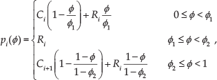
for the right support foot case, where the ϕ is the walk phase

Then we have the following closed-form solution of (1) with zero ZMP error during the step period

where
and for the right support case


whose parameters

The step definition, reference ZMP trajectory and resulting COM trajectory for the analytic ZMP controller
4.1.2. ZMP preview controller
Using a preview control over the reference ZMP trajectory [19] is a more generalized way to generate COM trajectory. From (1), we first define a new control variable ux as the time derivative of the acceleration of the COM

Then we can translate (1) into a strictly proper dynamical system as
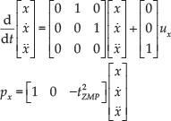
discretization of (12) with sampling time of T is then

where


Then, given the reference ZMP

where

where Gi, Gx and
4.1.3. Dynamic Switching between Two Subcontrollers
It is possible to switch between two controllers smoothly during locomotion, which we dub a hybrid walk control [18]. Transitions the analytic to the preview subcontroller are accomplished by using the boundary condition of the analytic subcontroller as the initial state of the preview subcontroller. Differentiating (6), we get following boundary values for
which will result in a continuous COM trajectory up to the second derivative over the transition. Transition from the preview subcontroller to the analytic subcontroller can be done by extending the performance index (14) with the boundary conditions

where
We add the initial and final preview step entries into the step queue to initiate the initial and final steps. The initial step has zero foot displacement while the final step is set to make both feet parallel. To simplify designing the ZMP trajectory for the ZMP preview subcontroller, we use the same trapezoidal ZMP trajectory as the one for our reactive subcontroller [17]. Figure 7 shows the ZMP and COM trajectories of the robot where the robot starts walking, takes a few step forward and then stops.

COM, ZMP and commanded velocity during a walking sequence generated by the hybrid walk controller. The first and last steps are generated by ZMP preview subcontroller, and the other steps are generated by analytic ZMP subcontroller.
4.2. Kick Motion Generation
Kicking the ball is an essential skill for robotic soccer. A powerful kick is important as the team with a more powerful kick has a higher chance of scoring than the team that requires several kicks to reach the goal. However, if they take too long time to deploy the kick, they will probably lose the ball to the opponent who has a weaker, yet quicker, kicks.
4.2.1. Stationary Kick Controller
When the robot stays statically balanced during the whole kick motion (meaning the COM of the robot always lies in its support polygon), the kick is called stationary. The simplest way to design such a kick is by utilizing the whole body scripted motion we explained in section 3.1, but it is very hard to design such a motion that works well on multiple robots.
Instead, we provide a stationary kick controller based on IK that we introduced in section 3.2. We define the kick sequence, which is composed of a number of individual torso or leg movement motions, and interpolate between them with either linear interpolation or a customized leg trajectory function to generate the motion. This way, designing and tuning a new kick is much easier than making a keyframe kick in joint space, since only a few human understandable parameters are used. Also, with abstracted parameters, the kick can be generalized to robots with different joint configurations. Figure 8 shows the stationary kick controller in action.

Examples of the stationary kick controller. (a) DARwIn-OP performing a high kick (b) Nao performing a backside kick.
4.2.2. Dynamic Kick with the Analytic ZMP controller
The main drawback of the stationary kick is that the robot must first fully stop and wait for some time to stabilize itself. However, when two robots are fighting against each other in close range, a quicker kick is generally much more helpful than a strong but slow kick. We extend the analytic ZMP walk controller to generate a quick kicking motion while walking, where the robot takes a number of pre-designed kick steps and custom foot trajectory to kick the ball harder than simply walking over the ball. However, due to the constraints with analytic ZMP controller, such kick is quite weaker than stationary kicks. Figure 9 shows some examples of kicks based on the analytic ZMP controller.

Examples of a dynamic kick using the analytic ZMP controller. (a) DARwIn-OP performing a front walk-kick (b) Nao performing a side walk-kick.
4.2.3. Dynamic Kick with the ZMP preview controller
To have both the power of the stationary kick and the speed of the dynamic kick, we also provide a dynamic kick utilizing the ZMP preview controller and dynamic switching of walk subcontrollers. To generate the kick motion, the controller is extended to use a custom foot trajectory, just like the analytic ZMP controller case.
The ZMP preview controller can take any reference ZMP trajectory as input, and generates a COM trajectory without any velocity discontinuity. As a result, the controller can replicate any kick motion the stationary kick controller can generate, as well as being more smooth. Figure 10 shows the full sized THOR-OP robot kicking in a simulated environment, as well as the ZMP and COM trajectories for the X and Y axes. For small sized robots, we mainly focused on keeping the speed and stability of previous dynamic kick, while increasing the kick power. As a result, we have significantly increased the average kick distance while keeping the total kick time almost same. Table 1 shows the comparison of the kick distances and times for the stationary kick, the dynamic kick with analytic controller and the dynamic kick with ZMP preview controller for DARwIn-OP robot.
Average kick distances (centimeters) and time (seconds) of DARwIn-OP robot


THOR-OP robot doing kick motion using the hybrid walk controller. (a) kick sequence. (b) X axis COM and ZMP trajectories. (c) Y axis COM and ZMP trajectories.
5. High Level Motion Control
With the controllers for basic skills ready such as walking, kicking and getting up, we need the high level controller that governs behavior level decisions. Each robot has to determine where to move first, and then the best way to approach the target position, and for attacking robot, the fastest way to align to the ball to kick. The high level decision is done using a number of parallel finite state machines (FSMs), which runs at slower rate than lower level controllers. As the walking motion is divided by discrete steps, the high level motion controller is called at the end of every step.
5.1. Role Specific Behavior Control
We have a number of different roles for the robots on the team, which can be categorized as the attacker, supporter/defender and goalie. The goalie stays in the best position in the penalty box to block the incoming kicks, and when the ball is close it approaches the ball to kick it away. When the attacker and goalie are both close to the ball, goalie has the higher priority to move to the ball. The attacker has the second highest priority, and charges to the ball as soon as possible unless the goalie is already close to the ball. Defender and supporter have lower priority, and they move into supporting / defending position as well as move away not to get in the way of attacker and goalie.
5.1.1. Behavior Planning
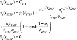
Unlike goalie or supporter/defender robots, the robot with attacker role requires a long-term planning. Instead of the grid based searches [20], we use a tree based search with discretized kick angles that can be computed very quickly. To determine the optimal sequence of kicks that maximizes the scoring chance while minimizing the failure chance, we first generate a kick tree, where each node represents a possible ball position that branches into different kick angles. Then for each path we evaluate the scoring chance based on the goal angle at the final node, and the failure chance that can result in out of bounds or colliding the obstacle. To prevent oscillating when traversing down the kick tree, we also penalize paths based on their difference from the best path chosen at the previous planning step. Figure 11 shows the planned attacking strategy in presence of two obstacles.
Simulated THOR-OP robot follows the planned trajectory and generates an optimized attacking strategy based on the perceived locations of obstacles
5.2. Walk Trajectory Planning
Once the optimal attack sequence is planned, the robot has to move to its first kicking position in shortest time possible. The commonly used tactic is first approaching the ball in a straight path and then orbiting around the ball till the robot is lined up with ball and the goal. However such a tactic is quite slower in practice as the bipedal robot cannot sidestep as fast as walking forward. Instead, we use the parameterized curved trajectory [21] learned by reinforcement learning, which can reduce the approaching time by 30 percent on average. Once the trajectory is generated, the maximum possible velocity within its stable region is selected as the commanded velocity. Figure 11 shows the resulting walk trajectory to the kicking position.
5.3. Walk Velocity Generation
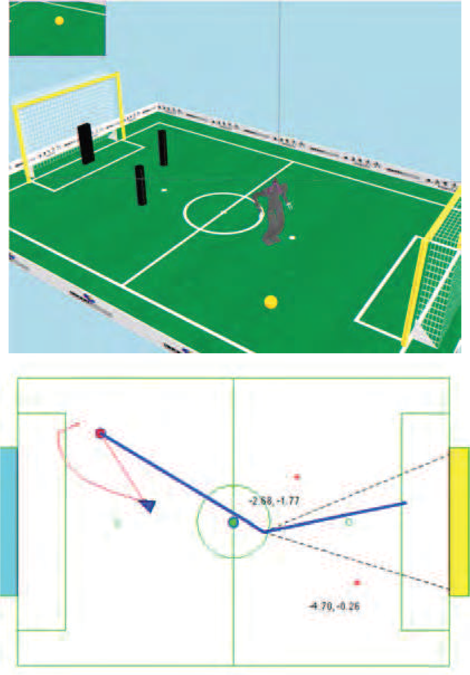
Once we have the walk trajectory to follow, we have to generate the control velocity as the input of the walk controller. We use the empirical walk velocity threshold and acceleration threshold to generate the velocity for next step. At this stage, we also handle the local obstacle avoidance using potential field, where each obstacle has a small Gaussian rejection field around it to repel other robots away from the obstacle [22]. Figure 12 shows an example of such potential field and resulting rejection velocity bias around the obstacle.
Local obstacle avoidance using the potential field
5.4. Foot Step Planner
When the robot is close to the ball, the control of torso velocity alone may be insufficient to make the robot stop with feet precisely aligned to the ball. One simple way to solve this issue is using progressively shorter step sizes when the robot gets closer to the ball, but that will result in wasted time which can be crucial when two robots are fighting over a ball. To minimize the number of the steps to align, we use a simple foot step planner where each footstep is optimally selected to minimize the distance to the target position while satisfying the kinematic and dynamic constraints.
6. Team Level Motion Control
A general rule of thumb in robot soccer is that “You can only win by a good team effort”. A single robot, however good it is, almost impossible to win against a well coordinated team of robots. Each robot has to communicate with one another to help localization, avoid collision with own teammates, and determine its role, all in distributed way. Throughout RoboCup, there are many examples of coordination including wheeled robots [23] and legged robots [24], setting a good precedent of work to study.
6.1. Robot to Robot Communication
Robots can communicate with other robots in various ways, either using wireless network, sound or vision. As the match commonly takes place in noisy environment, wireless network is the most preferred way of communication. As two robot teams should share a single wireless channel, communication bandwidth is strictly regulated, yet severe network congestion is commonplace. In our motion controller, each robot broadcasts a compressed data structure with global timestamp that contains various information such as current perceived position of itself, last observed ball position, current role and target position and so on. And each robot receives data packets from all other robots to make a distributed team level decisions. This team message passing and team level behavior decision runs every one second or less, based on the network condition of the field.
6.2. Active Role Switching
For our humanoids, each robot is assigned one of roles, an attacker, a supporter/defender and goalie, based on the current location of ball and robots. The role switching is dependent on the estimated time of arrival (ETA) of each robot to the position at which it kicks. The ETA is calculated by the walk trajectory planner, and each robot broadcasts its ETA to every other robots. The robot with the minimum ETA takes the attacker role, with hysteresis to prevent random oscillation between roles similar to [25]. the attacker is selected, other non-goalie players are assigned supporter or defender roles based on their relative position to other robots. To make sure team level behavior works fine without glitch, whole team of robot is repeatedly tested in the simulated environments. Figure 13 shows the role switching which has occurred during actual RoboCup game.

Role switching during the actual match (red team). (a) Left robot is attacking, and right robot is waiting in the defending position. (b) left robot lost the ball. (c) right robot is switching to attacker as it is closer to the ball now. (d) defending robot is moving back to defense, and attacking robot approaches the ball to kick.
6.3. Avoiding collision
It is not very desirable to let robot go into other robot and fall down, especially its own teammates. One way to avoid such a collision is using vision to detect other robots, but reliable vision based robot detection is still a hard problem. Instead, we use the localization information to avoid collision with our team's robots. Robots use localization based on landmarks and goal posts to estimate their position on the field. By knowing each robot's position in the world frame, and sending that information to its teammates, preventing unnecessary collisions using the potential field we addressed in section 5.3. An important and efficient aspect of this approach is the simulation based calibration of the radius of the potential field. This has to be tested during game play as well to get the optimal value. We can get a good estimate of the potential field radius while performing a minimal amount of tuning during field-testing with the actual robots.
6.4. Team localization
One of the big recent challenges for the RoboCup robot soccer league is the adoption of a fully symmetric field to make gameplay more compatible with human soccer. The goalposts on each side of the field are now required to have the same color; additionally, the unique half-field localization landmarks have been removed. This means that no unique landmark exists on the field, and the robots must keep track of their localization status using ambiguous information. But due to the symmetric nature of the field, the localization belief of the robot can be “flipped,” which happens often when the robot gets pushed at the very center of the field to accumulate lots of error in pose estimation.
To fix the flipped localization status, we used the localization information of other teammates. There can be only one ball on the field at a time, so if one robot sees a ball on the opposite side of the field where everyone else sees a ball, we can determine that the robot has a flipped localization status. We use a weighted voting method to detect the flipped ones, where the goalie has the highest priority as it rarely moves outside of the goalie box, and other robots have weights based on the ball distance and the distance from the center of the field. Figure 14 shows the flip correction in simulated environment.

Team based flip correction. (a) Both robots have the correct localization status. (b) The right robot falls down and get orientation reset. (c)The right robot now has flipped localization status. (d) Localization is fixed with a team ball observation.
However, we cannot use such a flip correction method if the ball is close to the center area, and robots can still kick and score the wrong goal from the center of the field. To prevent such mishaps, we assume that if the robot falls at the center field it instantly labels itself as confused. We do not allow the robot to kick directly to the goal until it is sure of its pose; instead, we make the robot move the ball to the side of the center field. In this way we can still keep the ball moving, while preventing the chance of scoring on our own goal. Additionally, it helps to disambiguate the localization based on the team information.
7. Perception Subsystem
Perception subsystem receives raw sensory data from sensors and processes them to provide situational cues for high level behavior decision. As the current RoboCup rule does not allow for active sensors, RGB camera is the main source of perception. For this case, the whole perception subsystem can be further divided into image capturing module, vision processing module and localization module. Although each modules can run separately, we consolidate all image processing into a single Vision process which contains the entire pipeline of image processing for RoboCup.
7.1. Image Capturing
For most cameras that is UVC compatible, we provide a driver made with the Video4Linux2 API [27]. If a robot's camera is not UVC compatible, a custom camera driver module should be made that also provide images, height, width, and other parameters required for the vision processing. The image capturing process runs in a separate thread for each camera, and constantly samples images from the camera as soon as a new frame is available. Once a new image data is captured, each pixel is classified into a number of preset colors using a lookup table, and the resulting labels are published in shared memory. To ensure the easy porting over different systems, we maintain a configuration file that specifies all camera parameters, such as white balance and exposure time.
7.2. Vision Processing
Once the color segmented image is acquired, a number of feature detection algorithms are used to detect possible visual cues from the current image. We use a number of low level image processing libraries, which includes blob detection, connected region detection and statistical analysis routines, to find the possible candidates in the scene and then apply a number of filters to get rid of false positives. As the analysis in the full resolution can take a long time, we also use low-resolution labels, which were generated by a bitwise OR operation, for initial filtering. Results of this pipeline are shown in figure 15.

Results of Image Processing, which shows the color segmented image and goal post, line and ball features detected [26]
7.3. Localization
During the match, the robot is never given a ground truth information of its location and angle, and it has to localize itself utilizing visual cues and information from teammates. The main landmarks used for localization are goalposts and lines, but they are ambiguous as the whole field is symmetric. We use a particle filter to disambiguate between unknown landmarks, while using inertial sensor for tracking heading angles. However, in some cases such as falling in the right center of the field, robot cannot re-localize by itself: in that case, robot uses the ball location information sent from other teammates to correct its heading angle as described in previous section.
8. Optimizing the Motion Controller
We have done extensive testing using both the simulated environment and actual robots to optimize each level of the motion controller. To test new theoretical contributions to the realm of RoboCup soccer, it is important to identify as many variables that can affect the system. For our team coordination, we found that we could conservatively test and tune some parameters in simulation. However, calibration for low level servo and walking parameters needed to be done in the real world only.
8.1. Low Level Motion Controller
In the simulated environment, multiple robots can have identical static and dynamic properties. However as physical robots are all different from one other, mainly due to the assembly tolerance, we need to bias them for optimal performance. For this purpose, we have developed an intuitive biasing script for precisely and efficiently biasing the servo zero positions. Biasing can be iteratively done by visually aligning the joint, modifying the zero value, and moving the joint to different positions until the resulting servo position is within a tolerable threshold.
8.2. Mid Level Motion Controller
Although the ZMP based locomotion controller we use theoretically guarantees the dynamic stability, the non-ideal nature of physical robot forces us to do additional manual calibration of locomotion parameters. This process can be automated in a simulated environment [28], but it is hard with actual robots due to the limited number of trials available.
We use an interactive test script to calibrate the parameters, that can iteratively tune the parameters online. The script lets the robot walk using each new bias parameters for immediate effect. On average, tuning the locomotion parameters from scratch for a totally new robot can take roughly one hour, and fine tuning existing parameters for a new surface takes less than that.
However, we have found that even after the joint level calibration, multiple robots can have slightly different torso positions during walking. Instead of trying to fix this using joint level calibration, we calibrate robot specific parameter biases so that every robot can walk stably up to the velocity threshold. As the surface condition greatly affects the stability of the locomotion, the velocity threshold is also empirically determined at this stage. For example, we set the forward walk velocity threshold to 32cm/s for the RoboCup 2012 competition where the surface was rather soft, and 40cm/s for the RoboCup 2013 competition where the surface was much harder and smooth.
8.3. High Level Motion Controller
As it is hard to quantify the high level strategies using real robot, we use the simulated environment to optimize the high level controller. We use the velocity threshold and average kick distance acquired from testing with actual robot, and utilize a reinforcement learning algorithm to optimize the parameterized trajectory to reach the kicking position. Once the optimal parameters are acquired, the motion controller is repeatedly tested using an actual robot to ensure that the robot remains stable during the approaching behavior.
8.3.1. Team Level Motion Controller
The team level controller is tested in simulation first, using repeated episodes. By using a physics based simulator with a simulated vision system, we could identify how multiple robots with different roles interact with each other under many different circumstances. These tests are difficult to conduct with actual robots due to time limitations. Many parameters for the team level controller are dependent on the quality of the vision and communication system, which is usually not very well known before actual matches. We set conservative values initially, and carefully analyzed actual match logs with synchronized videos to update those parameters.
9. Conclusion
This paper described a hierarchical motion control system that is able to provide multiple layers of robust decision making for humanoid soccer players. At the lowest level, a machine learning approach provides a mapping from inertial sensing to effective disturbance rejection locomotion. This same locomotion controller is able to incorporate this feedback, and provide a mechanism to switch between a nimble analytic walk controller and dextrous preview ZMP controller. At the higher levels, we provide a path planning system that minimizes the time to kick while avoiding teammate collisions.
While testing of systems in a laboratory or simulation can give incredible feedback in designing multi-robot systems, there is nothing like competition for learning about real world problems. During our competitions, we found both better parameters and better ways of debugging system behavior. For instance, we found that quickly executing kicks, even in a suboptimal direction, would vastly increase success during a match. Spending time to calibrate localization worked wonders for planning motions, as the real world began to reflect the simulation environment more. Deploying the robots also required diligent tracking of robot localizations, to understand if bugs in teammate avoidance behaviors was due to localization or poor parameters.
The system was tested in various simulation and real world environments, while being deployed yearly at the RoboCup soccer competitions. Being modular in design, the system has been verified on both kid-sized hardware of the DARwIn-OP robot and adult-sized hardware of the THOR-OP platform, and is released as a open source. 3