
Abstract
This paper proposes a framework for a virtual entity-based rapid prototype (VERP) to facilitate the design and simulation of humanoid robots. The VERP framework consists of three components: virtual entities, a high-fidelity simulation environment with physical and rendering engines, and an interface between the physical and simulation environments. To study the effectiveness of the proposed framework, we present a complete prototype for a humanoid robot using virtual entity modelling, control algorithm design and simulation. The humanoid robot is mathematically modelled with adjustable physical parameters which determine the kinematic and dynamic behaviour of the virtual entity in the simulation environment. With the simulated model, a control scheme for the virtual entity and the actual humanoid robot are designed and implemented through the interface. The empirical experiments and numerical analysis show the effectiveness and preciseness of the proposed VERP in terms of simulation fidelity, dynamic performance, and control interface.
1. Introduction
With the help of design and simulation platforms, robot models can be built and set up quickly while the control and intelligent algorithms can be debugged with debugging tools and simulated robots. Following a modular approach, a robot can be decoupled into functional components including appearance, mechanics, sensors and actuators, software components, and electrical interfaces to the system buses. The various applications of intelligent robots are carried out by combining software components such as navigation, path planning, identification, control and visual-audio processing. Therefore, modular design, functional simulation and offline programming can improve the productivity of robot design and debugging. Although a simulated robot might not have the level of complexity of design that it would have in the real situation, the simulation can rapidly verify the robot's design and control algorithms independent of the hardware platform [1]. Simulating with realistic physical interactions allows us to study the behaviour of different types of robots without building a complex hardware device in advance [2].
Some robot software for simulation and model design is available for robotics research. OpenHRP can provide various models for dynamics simulation [3]. It supports the ability to detect collisions between robots and objects in the environment. It can also provide cameras for robot vision, force/torque sensors and gradient sensors in the simulation environment. Webots [4] is a professional robotic develop environment which is widely used in research. However, it is difficult to modify some properties of the actual simulator. Microsoft Robotics Developer Studio could provide robot researchers and developers the tools needed to create robotics applications easily. The Darwin2K [5] and Evorobot simulators [6], which are used to develop robots for educational purposes, have a powerful capability to evaluate algorithms. The Virtual Robot Experimentation Platform [7] is a robot simulator with an integrated development environment that can be used to simulate, test, evaluate or interface with whole robotic systems (mobile robotics, industrial robotics, etc.) or robotic subsystems (mechanisms, sensors, etc.). It is a general-type robot simulator that virtually supports any type of robotic system through its fine-grained functionalities and extended Application Programming Interface (API).
However, the current simulators and design tools are not especially designed for developing humanoid robots. Most of those simulators are designed for process-oriented workflows. Humanoid robots consist of numerous different sensors and executors, and their controllers determine the robot behaviours according to simultaneous and uncertain feedbacks collected from their working environment through various sensors rather than from process-oriented workflows.
To simplify the robot's design and evaluation, a virtual entity-based rapid prototype developing framework (VERP) is proposed for humanoid robots. In VERP, a modelling tool for a rapid prototype is designed with numerous sensors and actuators, such as cameras, laser range finders, motors. A real-time simulation environment is also designed for structured and non-structured environments. In order to form a closed-loop control system, the simulation environment and the humanoid robot should communicate with each other effectively. The controller module can acquire the sensor's status provided by the simulation environment. In addition, the programs can be tested with both the real and simulated robots in the loop before being downloaded into the target robot. The main contributions of this paper are highlighted as follows:
A framework for a virtual entity-based rapid prototype is proposed for the simulation and design of humanoid robots;
The general model of humanoid robots is provided in the simulation environment with joint definitions and kinematics;
The gait control is designed for the virtual humanoid entity and the performance of the algorithm and simulation system is evaluated and studied.
The rest of the paper is organized as follows. The framework and design concept are discussed in detail in Section 2. In Section 3, a general virtual humanoid robot is modelled with kinematics analysis and gait plan to facilitate control design and simulation study. In Section 4, gait control of a single humanoid robot, the coordination of multiple humanoid robots and a hardware-in-the-loop simulation are conducted to test the performance of VERP in robot modelling and simulation. The conclusions come at the end of this paper.
2. VERP framework
The aim of the VERP framework, as shown in Figure 1, is to facilitate the design and simulation of humanoid robots in rapid prototype and module design. To test and verify the prototype and controller, VERP provides the simulation functionalities in the virtual environment with real working conditions through the standard communication interface [8]. In addition, the algorithms can be downloaded into the robot platform or cross-compiled using VERP. Within the VERP framework, a virtual entity-based prototype of a humanoid robot can be easily built with the 3D modelling software. With the entity editors, the physics of the virtual entity of robots can be defined in the virtual environment for dynamic simulation and design of intelligent algorithms. The performance of the algorithms can be evaluated on the virtual robot within the simulation environment. If the virtual robot performs as expected, the VERP downloads the controller's executable codes to the real robot's hardware and generates the robot prototype.
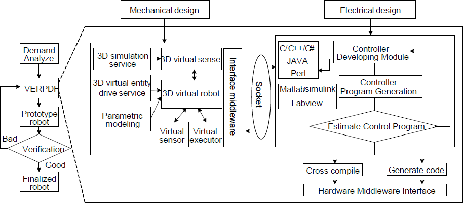
Design and simulation in the VERP framework

Virtual entity in the loop with HAL
The simulation platform supplies a software development platform for robot designers and users by building a simulation robot that is exactly the same as a real robot in terms of physical performance and appearance. It helps robot users implement off-line programming without using real robots and thus improve the efficiency of the entire process of developing intelligent robots.
2.1 Visual and physical modelling
The physics engine gives objects the real physical attributes needed to make them move, rotate and collide in accordance with the rules of the objective world. The physics engine calculates every entity's displacement, velocity and status information and then updates the entity's orientation to create a new virtual scene. VERP uses the PhysX as the fundamental physics engine to perform state analysis and the physical simulation of the physical entities which have physical attributes. PhysX is a physical calculation engine used to build the applications of particles, fluids, soft-body, joints and cloth. This engine can simulate interactions with the surrounding environment while objects are moving to let users experience more vivid physical effects and make the development of algorithms convenient. The physical parameters of virtual entities are adjustable, such as coordinates, location, velocity, acceleration, momentum, force, rotation, energy, friction, impulse and so on. In VERP, some of the functions are wrapped and redefined as standard abstraction to facilitate the fast prototype and to break the limitations of the predefined scripts for high physical fidelity. The commonly used physical parameters are shown in Table 1. The physical model of the humanoid robot is reconfigurable in terms of the structural parameters and physical parameters according to the true specifications of the humanoid robot.
Adjustable simulation parameters

With the physical models, the rendering engine in the 3D virtual scene visualizes the virtual entity of the robot. The VERP adopts OpenGL as the rendering engine, which provides basic graphic elements such as point, line, polygons and so on. The users of VERP are able to construct more complex models of robots with the basic blocks. For a good visualization, the rendering effects including merge, antialiasing, fog, texture mapping, frame buffer and light can be reconfigured and designed. The VERP provides loading mechanisms and the virtual robot models can be imported into the simulation environment directly to generate the visual effects. It is very trivial and inefficient to build and debug robot models manually in the design and simulation. Therefore, the properties of robot models are stored and edited in a XML framework for good expendability, flexibility and representation with the design principle of “what you see is what you get”.
2.2 Virtual entity in the loop
Different robots come with different sensors, actuators and interfaces in the physical and simulated worlds. To reuse the codes and standardize the interfaces, we provide the hardware abstraction layer (HAL) in VERP, allowing us to compose hardware independent codes both for actual and simulated robots. With this functionality, we create software architecture to monitor all devices and high-level modules can access the sensors and actuators regardless of the properties of the actual sensors.
Another important issue is how we can construct the robot models, the environmental models and sensors/actuators properly in a robot developing environment. Improper and imprecise models may result in wrong outputs and infer incorrect conclusions. In the robot modelling environment, model description files include robot mechanical structure models with proper defined sensors/actuators and the virtual environment information. Together with the visual configuration, the simulated robots provide a common control interface and sensor data from the robots and the environment.
2.3 Communication interface
With the HAL, we abstract and standardize the interfaces of sensors and actuators. As for the intelligent algorithm design, there are many different programming languages available that are designed differently depending on the research field they are to be used in, such as C, C++, C#, Python and Matlab. For the benefit of various users, VERP uses the multiple programming interfaces for C/C++ and Matlab. Moreover, it is very convenient for the end users to be able to design their own language interfaces with the provided standard libraries so that they can reuse the pre-designed algorithms. By providing the fundamental models for different algorithm design and realization as well as the general programming interfaces, the efficiency in coding and simulation can be greatly improved and the robustness of the algorithms is enhanced at the same time.
In each simulation cycle, the physical interactions between the environment and the robots are monitored by the physics engine in a fixed time interval for high-fidelity simulation while the appearance is updated by the rendering engine as fast as possible for the best visual effects. The program can be verified in the simulation environment to control both the simulated and actual robots for hardware-in-loop simulation. Through the HAL, the simulation program developed in the VERP system can be conveniently transported into the actual robot with the same interface and then the robot algorithms are ready to be compiled and downloaded to target robots.
3. Humanoid robot model for VERP
3.1 Generic virtual model of humanoid robots
Within the VERP framework, we designed a generic humanoid robot for the research of gait plan, control design and multi-robot coordination. We adopt a simplified model instead of the full representation of human mechanisms. The mechanism's main function will be biped walking. Thus, there are six degrees-of-freedom (DOF) on each leg and three DOFs in each arm, which are designed to keep balance while walking. In addition, the head has DOFs to control the direction of view with mounted cameras. Therefore, the whole virtual entity comprises rigid bodies and linkages with a total of 21 DOFs, shown in Table 2. Figure 3 shows the size of each part of a humanoid robot in general.

Virtual entity of humanoid robots
DOF of each joint

In addition to the design of the mechanical model, sensors and executors are very important for the control and study of the virtual model. The robot is equipped with three kinds of sensors: a camera is mounted on the head, a gyroscope is fixed to the trunk and angular sensors are installed on each joint. The executors in the robot are steering gears mounted on DOF. The final prototype is shown in Figure 4.

The kinematic model of lower body
Specifications of the virtual humanoid robot

To facilitate the modelling of the humanoid robot, the world and local coordinates are defined according to right-hand rules unless otherwise specified, where the world origin is located in the intersection of the central vertical line with the ground plane with the x axis pointing to the left, the y axis pointing upward and the z axis pointing to the front. The lower body plays important roles in the biped walking and the lower body is modelled as in Figure 4 according to the general structure of humanoid robots. The upper body is represented by a body node located in the centre of the robot trunk. It is worth noting that the centre is not the centroid of the robot which is determined through forward kinematics. There is only one freedom in each joint and the length of the links is determined by the distance between adjacent joints.
The humanoid robot is a complex system with multiple joints and linkages, whose movements influence their own pose and position as well those of others. For the sake of computation simplicity, the data of the joints are stored and processed in a tree-structure. As defined in the graph, the “right hip yaw” represents the rotating angle of the right hip around the y axis in an anti-clock-wise direction, the “right hip pitch” denotes the rotating angle of the right hip around the x axis in an anti-clock-wise direction, and the “right hip roll” describes the rotating angle of the right hip around the z axis in an anti-clockwise direction. The rest of the denotations may be deduced by analogy. Thanks to the merits of this data structure, data searching can be performed effectively in a recursive way.
3.2 Forward kinematic model
Forward kinematics is fundamental in the control and simulation of humanoid robots by computing the pose and position of each part [9]. With forward kinematics, the joint angles of the robot can be mapped into the pose of each part for behaviour control and gait generation.
Given a single linkage, let the world coordinate of the parent linkage be p0 and R0, the relative pose of the child linkage to the parent be 0p1 and 0R1, so the transition matrix of the child linkage to the parent one is
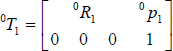
The transition matrix of the parent linkage is

According to the chain rule of transition, the transition matrix of the child linkage relative to the parent linkage is [10]

Therefore, the pose of the child linkage in the world coordinate is p0 + R0 0p1 and R0 0R1.
For the virtual entity of the humanoid robot, the legs can be modelled as linkages with six DOFs with joint definition as in Figure 4. With the treelike data structure in Figure 5, the forward kinematics can be computed recursively using the chain rule of the coordinate transition.
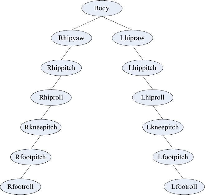
Data structure
3.3 Inverse kinematic model
In the behaviour control and gait plan of the humanoid robot, the angles of each drive joint need to be computed with the targeted position of individual parts. The reverse kinematic computation is difficult and time-consuming, especially for the general model defined in this paper, where the three joints of the hip are located in the same position.
Since the left and right legs of the humanoid robot are independent, we only derive one leg with six joints and the other one can be deduced similarly. Suppose the pose of the upper body is p1 and R1, and the pose of the right ankle is p7 and R7, the pose of the yaw joint of the right hip can be determined directly as

Since the position of the yaw joint and the pitch joint is the same, it follows that p3 = p4 = p2 o Let r be the position transition of the roll joint of the right foot, it follows that

and

As shown in the triangles in Figure 6(a), we can get

Inverse kinematics

This corresponds to the triangle composed of the yaw joint of the right hip, the roll joint of the right foot and the pitch joint of the right knee. In the triangle, the c and a denote the length of the thigh and calf of the leg, and c is the mode of r. Thus we can conclude that the angle position of the pitch angle of the right knee is q = π – ∠ABC. In Figure 6(b), with ∠a1 equals to ∠ACB, it follows,


where ∠a3 is the pitch angle of the right foot and the roll angle of the right foot is
According to chain rules, the transition matrix for the roll pose of the right foot can be determined iteratively as

where 1R2, 2R3 and 3R4 are the transition matrices of the three hip joints respectively. Given R1 and R7, we can further have

Let the yaw angle of the right hip be α, the pitch angle of the right hip be β, and the roll angle of the right hip be θ, we have

where

we conclude that

and the left leg can be determined in the same way. Using the mechanisms of VERP, the testing system is designed for the kinematics research and action design of humanoid robots as shown in Figure 7.
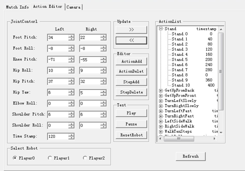
Real-time test and debugging system for kinematics and action design.
3.4 Behaviour control
In the existing literature, there are mainly three types of gait planning for humanoid robots: offline plan, online plan and adaptive offline plan [11]. The offline plan method is fast and easy to implement and it works by computing the detailed trajectories of each joint, yet the adaptive performance to the dynamic environment is very weak. On the other hand, the online plan technique relies solely on the sensor information and plans autonomously in real time. The online plan is difficult to implement effectively owing to the complexity of the environment and the fact that the walking stability of the humanoid robot cannot be guaranteed. In this paper, the basic control of the virtual humanoid robot is designed using geometric constraints for a compromise between flexibility and adaptability. The gait plan will succeed if the stability criterion is guaranteed although the modelling is complicated.
As the pose of the body and ankle determines the angles of the joints in the leg, the whole body trajectory is planned by controlling the path of the two feature points. In this paper, the vertical movement of the body is not evaluated during forward walking. The utmost and end positions of the feet are first confirmed and the other key points are computed by fitting using spline. The whole gait cycle is given in Figure 8, where the number of the key points depends on the transiting time of the body.

Trajectories of key points during a gait cycle
With the planned key points of the body and ankles, the desired joint angles of humanoid robots are calculated using the inverse kinematics model. The trajectories of both legs in one gait cycle are plotted in Figure 9.

The trajectories of joints in the leg during one gait cycle.
4. Evaluation of the VERP performance
4.1 Gait control
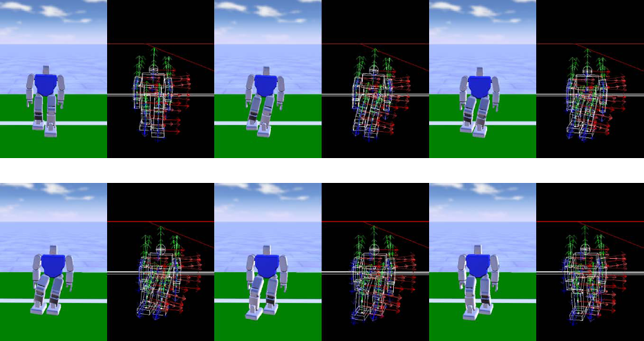
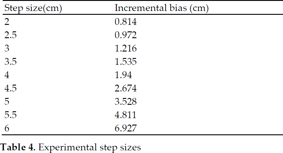
The behaviour control sequences from the gait planning are recorded in the “action file”, which can be reloaded in the platform to control the virtual entity. In general, a complete gait consists of three types of continuous actions including start, transition and finalization. Using the ZMP [12] (Zero Moment Point) planning method, the movement of the virtual entity is shown in Figure 10, 11 and 12. In the platform configuration, the timing of one movement cycle is 450ms and the control delay between adjacent joints is 30ms. In this paper, the gait stability is evaluated by measuring the bias between ZMP and the centroid of the other foot, the experimental data in the platform is shown in Table 5. As shown in the table, the bias between ZMP and the centroid of the supporting foot increases as the step size grows, while the walking speed increases. As a compromise between walking stability and speed, the step size is set at 4 cm in the experiments.
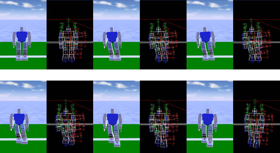
Movement sequence of the left leg
Movement sequence of the right leg

Finalizing movement
There are 16 states in each walking cycle in 450ms. In order to analyze the walking stability, the ZMP biases are summarized in Table 4. From the experimental data, it is concluded that the platform can precisely simulate and control the gait and behaviour of the humanoid robot during the stable walking that is designed with gait design method. In tests of continuous walking, the average walking speed of the virtual humanoid entity is 0.173m/s, which is the normal configuration of actual humanoid robots.
Experimental step sizes
4.2 Hardware-in-the-loop simulation
In the hardware-in-the-loop simulation, we apply the same gait control algorithm to the simulated and actual robot within one walking cycle. As shown in Figure 13, the virtual and physical robots perform an action sequence of the gait plan similarly under the same parameter configurations and environmental setup. The intelligent algorithms that are developed and debugged in the simulated environment can be seamlessly transported to the robot hardware with small adjustments thanks to the HAL.

Comparison of virtual and actual robots in the hardware-in-the-loop simulation.
ZMP biases in each state

4.3 Multiple robot system simulation
With the tools of VERP, multiple robot simulations are designed and tested in the control and coordination of a group of humanoid robots as shown in Figure 14. Each of the simulated robots manages the individual control logic of sensing, decision-making and acting. In the simulation, the control strategy is determined by external programs via the control interface. Through the multi-robot simulation, it is proved that the VERP simulation is able to handle the control and communication among multiple robots while guaranteeing the smoothness and fidelity of the simulation.

Simulation of multiple humanoid robots
5. Conclusion
With the aim of facilitating the design and development of humanoid robots, the virtual entity-based rapid prototype developing framework (VERP) has been proposed. The VERP framework consists of three major components, the high-fidelity simulation environment, virtual entity design tools and communication interfaces. With the design tools in VERP, a generic model for humanoid robots is derived with kinematics and gait control. In the simulation, the advantages of VERP have been shown for fast prototypes, virtual entity simulations and hardware-in-the-loop simulations, and multiple robot design and cooperation.
Footnotes
6. Acknowledgement
This study was supported by the National High Technology Research and Development Program of China (863 Program) (No. 2012AA041402), and National Natural Science Foundation of China (No. 61175031).