
Abstract
To replace human beings for a task conducted in a realistic environment, the ability to perform impact motions such as running, jumping, and carrying is required for a humanoid robot. At present, it is quite difficult for the humanoid robot to achieve the motion performance of human beings. To address this issue, this article proposes to use a novel impact motion control method for a humanoid robot called BHR-5 using energy integral method. First, we have designed a high power density joint controller to drive each brushless motor to actuate each robot joint. The joint controller can generate sufficient power to actuate the robot joint with an instantaneous overload when limiting the input power in a unit interval. Second, the control system can generate trajectories to realize impact motion by integrating the energy of the whole body. Finally, we have conducted performance test on BHR-5 to verify the control method using our motor drivers and trajectory generation method. Analysis of the experimental results confirmed the effectiveness of the proposed control method for performing impact motions.
Introduction
Humanoid robots are expected to replace humans in a variety of environments to perform independent or assistance tasks. For this purpose, humanoid robots should implement different kinds of motions such as running, jumping, or carrying. It means that the robot is required for the ability to support enough fast or powerful action. Unfortunately, it is quite difficult for the humanoid robot to achieve the motion performance of human beings with skeleton and musculature. Thus, a large portion of studies have focused on improving the motion performance of the humanoid robots.1–16
For several years, many researchers have proposed a considerable number of approaches in terms of mechanism, actuator, or control method. Among these methods, the most fundamental way is changing the mechanism or increasing the power of the actuator.1–5 Niiyama et al. 1 proposed a bipedal robot “Mowgli” with an artificial musculoskeletal system. Hosoda et al. 2 used antagonistic pneumatic actuators to produce a biped robot for multi-modal locomotion. Verrelst et al. 3 proposed a pneumatic biped Lucy actuated with pleated pneumatic artificial muscles. Although the pneumatic or hydraulic transmission can generate enough power, it will cause increased heavy and large compressors in humanoid robot. As electric motors are typically used in many humanoid robots, improving the potential of the motor energy is attractive.17,18 Urata et al. 18 analyzed a temperature control method to extract inherent performance from motors to achieve high power. This method required placement of temperature sensor and coolant round the motor which increased the complexity of the system.
Other researchers discussed on humanoid robot control algorithm to produce more powerful motion.6–12,19 Yoshida et al. 6 discussed an optimal posture of a humanoid robot for generating large desired force. Roussel et al. 20 proposed an optimal energy method for searching for a trajectory that fulfills a certain objective in terms of the gait parameters such as the walking velocity, the step length, and the step frequency, while minimizing the input energy. Ge et al. 21 proposed an adaptive predictive control mechanism using the advantage of data-driven technique combined with online parameters estimation strategy in order to achieve an efficient approximation. Li and Ge 22 proposed a structure for robust adaptive control for biped robots, which included balancing and posture control for regulating the center-of-mass (COM) position and trunk orientation of bipedal robots in a compliant way. Konno et al. 10 proposed an impact dynamics model and sequential optimization to generate impact motions for a humanoid robot. Cho et al. 11 performed a balancing strategy for hopping humanoid robots against various magnitudes of disturbance. These methods have effective performance but are limited to specific parts of body and motions.
In this article, inspired by the work in Urata et al., 18 Grosu et al. 23 and Yu et al. 24 and extending our previous work in Yu et al.,14,25 a novel impact motion control system of the humanoid robot based on energy integral method is proposed. For the purpose of preserving the working space of the humanoid robot, our control strategy is to act on improving the force of the joint actuator and the motion pattern generation algorithm. First, as the permanent magnet motors are typically used in many humanoid robots, a high power density joint controller is designed to drive the brushless motor as the actuators. By calculating the energy integral in time unit, the joint controller drives the motor to produce exceeded force safely. Second, humanoid robot trajectories generation method is presented based on the energy distribution of the whole body joints. This method can create fast or powerful motion patterns to finish impact motion. Combining the drive ability of the joint controller and the motion pattern, the humanoid robot can achieve impact motion in actions such as walking and hitting the ball more effectively.
The remaining article is organized as follows. In section “BHR-5 humanoid robot platform and impact motion control strategy,” the overview of the humanoid robot BHR is described and the impact motion control strategy is introduced. In section “Energy integral control of the robot joint,” we introduce the design for a high power density joint controller by energy integral method. In section “Trajectory generation based on energy distribution,” humanoid pattern generation method is presented based on the energy distribution of the whole body joints. In section “Experiment,” the experimental results on joint controller and the motion planning on walking and playing table-tennis are described. Finally, conclusions are given in section “Conclusion and future work.”
BHR-5 humanoid robot platform and impact motion control strategy
Overview of the BHR-5 humanoid robot
The novel control system was developed by converting our latest humanoid robot platform BHR-5 shown in Figure 1. BHR-5 has a total of 30 degrees of freedom (DOFs), and consists of two legs, two redundant arms, a torso, and a head. The joints configuration is shown in Table 1.
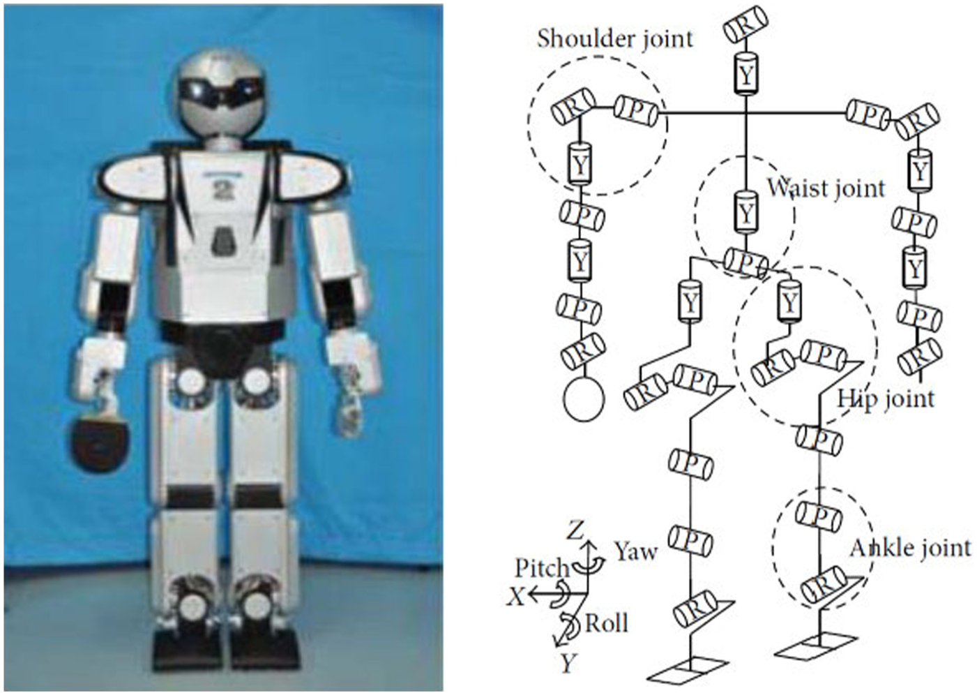
Overview of the BHR-5 humanoid robot.
Configuration of the joints.

The height of the BHR-5 humanoid robot is 1.62 m, and its weight is 65 kg. The mechanical frame and skeleton are made of aluminum, and the exterior is made of hard plastic. The robot is powered by lithium-polymer battery, and each joint is actuated by brushless direct current (DC) motor and harmonic drive gear. The robot also contains color cameras, gyroscopes and accelerometers, and six-axis force sensors. It contains a distributed real-time control system for the motion control and information acquisition. It is capable of walking up to 2.0 km/h and manipulating a variety of objects, for example, playing table-tennis.
The control system of the humanoid robot is shown in Figure 2. It is composed of two main parts: the vision and audio computer system and the real-time motion control system. The vision and audio computer system is responsible for vision and audio processing with Windows operating system. The motion control system is used to coordinate the acquisition of sensors and the real-time servo control for all the joint controllers of the legs, arms, torso, and head. To achieve real-time capability, the motion control computer uses operating system with Linux plus RTLinux core. The Ethernet and controller area network (CAN) bus are used to exchange non-real-time data and real-time data, respectively, between the vision and audio computer and the motion control computer. The CAN bus works at 1 Mbps. Two six-axis force/torque sensors are located on each foot to measure the contact force and torque between the foot and the ground. And then force/torque data are acquired by a four-channel peripheral component interconnect (PCI) interface card to compute the actual center of pressure (COP) for stability control.

Control system architecture for BHR-5 robot.
Impact motion control strategy
The purpose of this article is to realize impact motion in BHR-5 humanoid robot without influencing its working space. Based on this purpose, we present a novel system by improving the force of the joint actuator and the motion pattern generation algorithm. Improving the force of the joint actuator can make the motor to generate enough power to drive high speed movement. The motion pattern algorithm can combine different joints to produce impact motion together.
In this article, we propose the following impact motion control strategy: first, a new joint controller is required. The new joint controller needs to be provided with the follow functions: (1) enough power capacity to drive the motor, (2) intelligent arithmetic to maintain the motor working safely, and (3) robust communication to exchange joint parameters with the real-time motion control system.
Second, a new pattern generation method based on joint energy distribution is needed. While implementing the impact motion, some robot joint may reach the limit condition such as the knee at running or shoulder at swing. When some joints come to limit, the pattern should be adjusted to allocation energy in all joints to finish impact motion.
According to aforementioned strategy, the following sections give the detailed design method.
Energy integral control of the robot joint
Permanent magnet motors are typically used in many humanoid robots. The fundamental solution to achieve impact motion is extracting the potential power of the motor. When the permanent magnet motors rotate, the energy is transferred through motor to drive gear. This transmission process causes increase in temperature of the motor winding wire. When the temperature reaches the limit of the winding wire, it causes burnout of the motor, which is a typical damage to the humanoid robots. This article proposed a method to control the energy transformation in time unit to restrict the motor working under a same level steadily. This method can not only extract the potential power ability of the motor but also ensure the work safely.
Energy integral model of the motor
The physical control model of permanent magnet synchronous motor is shown in Figure 3.

Physical model of permanent magnet synchronous motor.
The voltage equation of permanent magnet synchronous motors in d-q synchronous rotating coordinate system is defined as

where,

where
The energy integral model of permanent magnet synchronous motor is formulated based on the electromagnetic torque. According to the energy conservation theory, torque work is equal to the kinetic energy increment. It means that we can get an integral model based on the theorem of kinetic energy of the motor rotational motion. In consideration of the transformation energy in every instant,
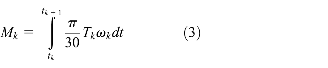
According to Figure 3,

BHR-5 humanoid robot uses the inner rotor brushless DC motor, so we can get

This equation describes a method that controls the current magnitude in time unit to realize energy integral. From this equation, we can derive that increasing the current in short time is an effective way to produce high power output. On the other hand, restricting the energy integral in a period will protect the motor from burnout.
Joint controller hardware configuration
According to the previous sections, the joint controller should have the capacity of providing large enough power to drive the brushless DC motor. Therefore, a high power density design is needed to ensure that the controller with small size can be set in the humanoid robot. According to the requirements in previous section, the control system hardware structure is shown in Figure 4. The isolated transformer provides power supply for all parts of the controller. With the pulse-width modulation (PWM) signals, the metal–oxide–semiconductor field-effect transistor (MOSFET) invert circuits convert input DC power into three-phase sine wave to drive the motor. High precision Hall current transducer is used to measure the current to implement energy integral control. Other sensor units and communication circuit are also provided. The digital signal processor (DSP)-based control unit is used for servo drive, energy integral control, and communication with the motion control computer. With 32-bit microcontroller CPU, the controller can handle position, speed or force/torque command, as well as real-time monitor the joint status.
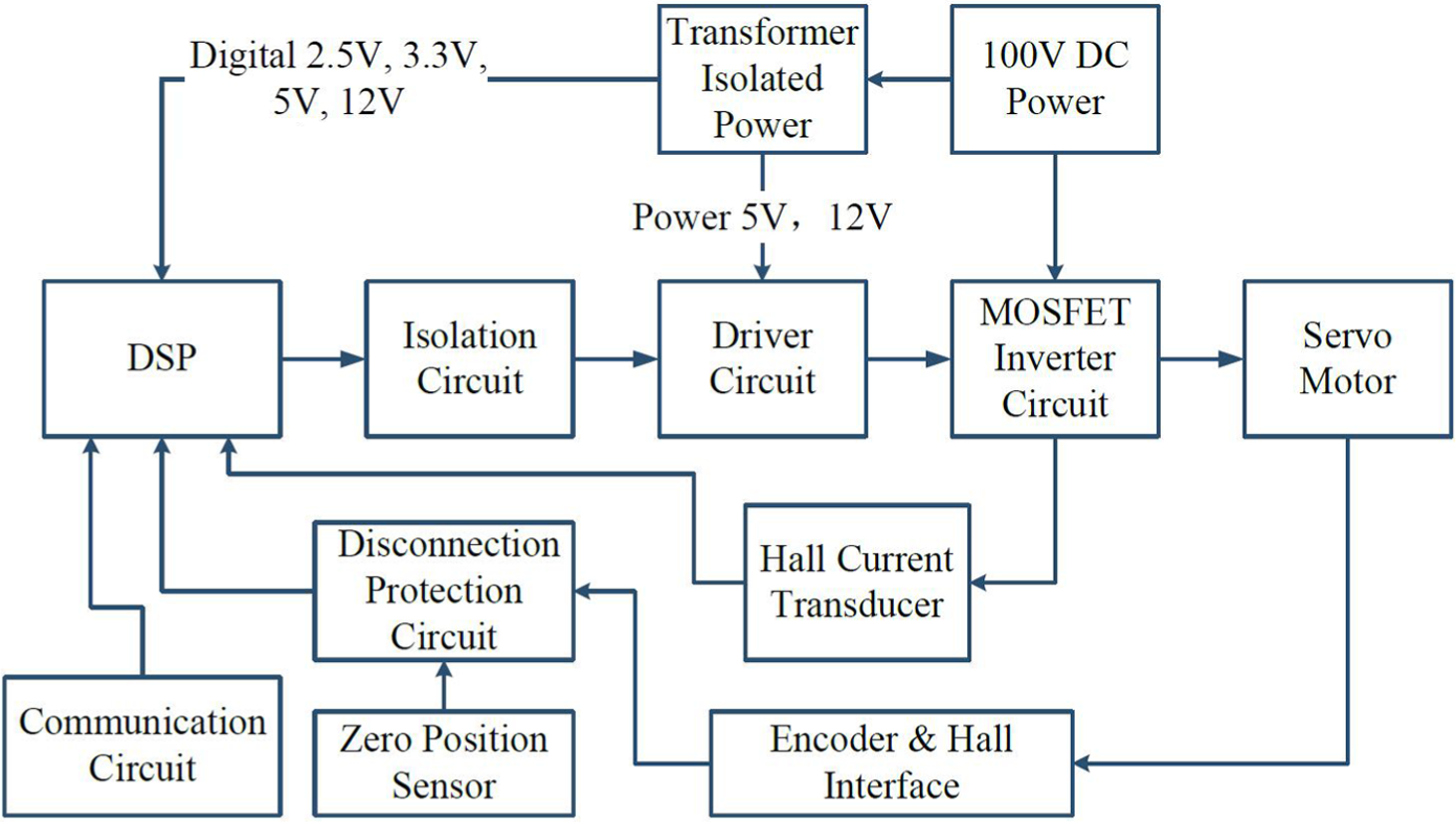
Hardware structure diagram of joint controller.
Joint controller software structure
To achieve energy integral control, the joint controller software flowchart is shown in Figure 5. After power on, the system will initialize the internal and peripheral variable first, which makes all sensors ready, at the same time, the controller also completes initialization and self-test. If the self-test is finished without problems, the system enters the synergic control state. If the joint controller receives position, speed or force/torque command from the motion control computer, it begins precise control according to the instruction. During the motion, energy integral control is activated. The control can drive the motor at exceeded fast speed at a short time to finish impact motion. At the same time, if the energy integral reaches the threshold, the controller enters the hypomotility control state to protect motor from burnout.

Main software flowchart of the joint controller.
Joint movement is realized by motion control algorithm. According to the energy integral model described in previous session, the designed algorithm diagram is shown in Figure 6. The motion control algorithm can be divided into the following parts: space vector PWM (SVPWM) controller, configuration, current loop, speed loop, position loop, and torque loop and protection functions. Sinusoidal PWM (SPWM) is a very popular technique used in alternating current (AC) motor control. This relatively unsophisticated method employs a triangular carrier wave modulated by a sine wave, and the points of intersection determine the switching points of the power devices in the inverter. This article uses a more sophisticated technique SVPWM for generating a fundamental sine wave that provides a higher voltage to the motor and lower total harmonic distortion (THD). It is also compatible for use in vector control (field orientation) of AC motors. Proportional–integral–derivative (PID) control is used in the major process of current, speed, position, and torque loop. It uses the error
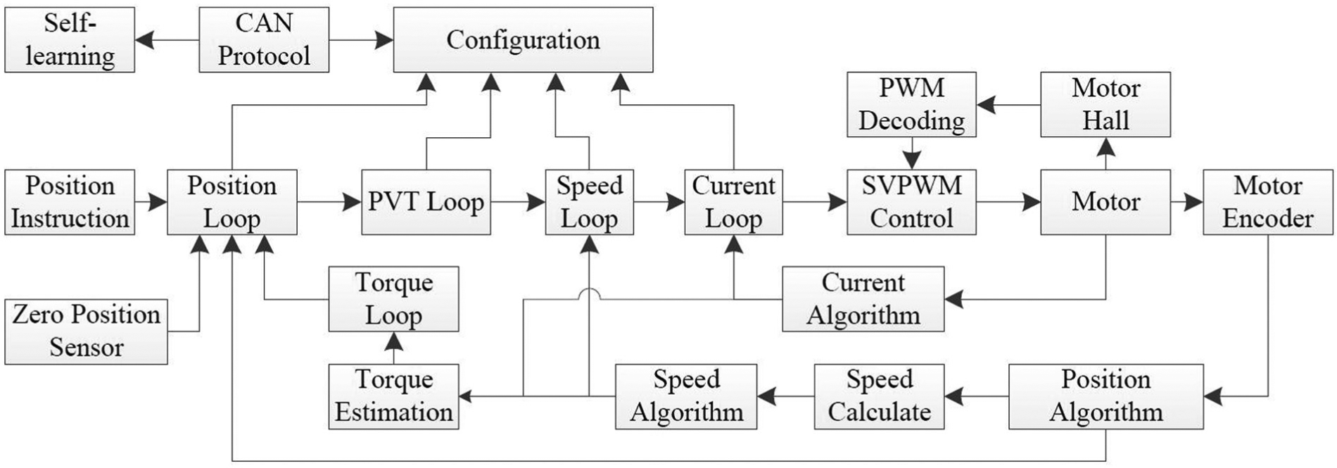
Motion control algorithm diagram of the joint controller.
Trajectory generation based on energy distribution
Basic locomotion patterns
The software structure of the motion control computer is shown in Figure 7. The software structure is divided into three layers: energy distribution prediction layer, online trajectory planning layer, and joint servo control layer. RTLinux is used as the operation system to meet the real-time requirements. In order to construct an open and real-time control system, CAN bus (CANopen protocol) is used for communication protocol between motion control computer and joint servo controllers.

Layered software structure of the motion control computer.
In order to arrive at working position or adjust operation posture, a humanoid robot might make use of some basic locomotion patterns. These basic patterns include forward walk, backward walk, turn-about, taking a forward/leftward/rightward step, standstill, mark time, and so on. It is obvious that the humanoid robot cannot link locomotion patterns together at random. For example, if we make the robot to stop walking and then if a standstill pattern is linked to a steady forward pattern, the robot will tip over easily. However, we can link a deceleration forward pattern first, and then link the standstill pattern. The possible locomotion pattern transition is illustrated in Figure 8.
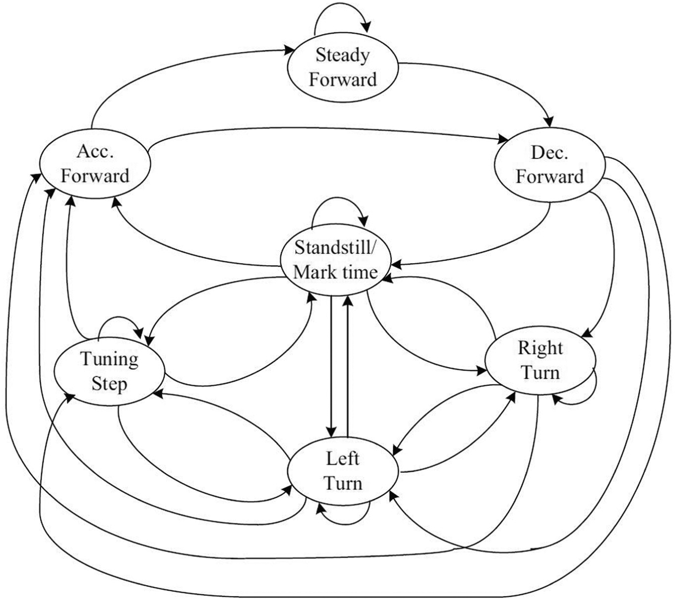
State transition of locomotion pattern.
Impact motion trajectory based on energy distribution
The generation procedure of the racket trajectory is shown as Figure 9. First, according to the location and velocity of the planning joints, as well as the desired target point on the workspace, the required attitude, velocity, and location of the joints at target point are solved. Then, joint achievement motion ability is assessed by computing the required attitude, velocity, and location of the joints at working plane according to the energy integral. Based on the joints motion ability, we can get a series of points of the joints moving at the constant attitude and velocity according to the energy distribution. After that the motion control computer solves the inverse kinematics related to the above points, to get the corresponding joint angles. Finally, we adopt the third-order spline interpolation method to generate all the joint angles in every servo cycle.

Planning algorithm for impact motion trajectory.
Experiment
Joint controller experiment
The implementation of the proposed high power density joint controller is shown in Figure 10. The size of the joint controller is 85 mm × 64 mm × 25 mm, which is small enough to settle in the trunk of humanoid robot. Table 2 shows specifications of the joint controller. BHR-5 humanoid robot adopts maxon 200 W brushless DC motors as actuators of powerful joints. Then, the following experiment is implemented using this motor.

Photo of the proposed joint controller.
Specifications of the joint controller.

The proposed joint controller can control the instantaneous current to utilize the maximum performance of a motor. Figure 11 shows the safe operation time of different current. It is showed that the controller can improve the potential of the motor energy in a short time.

Safe operation time of different current.
Figure 12 shows energy integral of continuous running. In this figure, light color represents the current and the dark line represents the energy integral equivalent. From the figure, we can see that the proposed joint controller using energy integral method can not only produce high power in a short time but also limit the current automatically to protect the motor.

Energy integral of continuous running.
Humanoid robot motion experiment
In order to verify the designed control system of the humanoid robot, we performed working motion and compared with the previous result. Figure 13 shows the impact motion of the knee joint during walking. The short dash line describes the previous result, and the solid line describes the result after using the new control system. It demonstrated that the control system can reduce the error effectively. From the top of the speed curve, it can be seen that the improvement is caused by the instant impact motion of the joint.
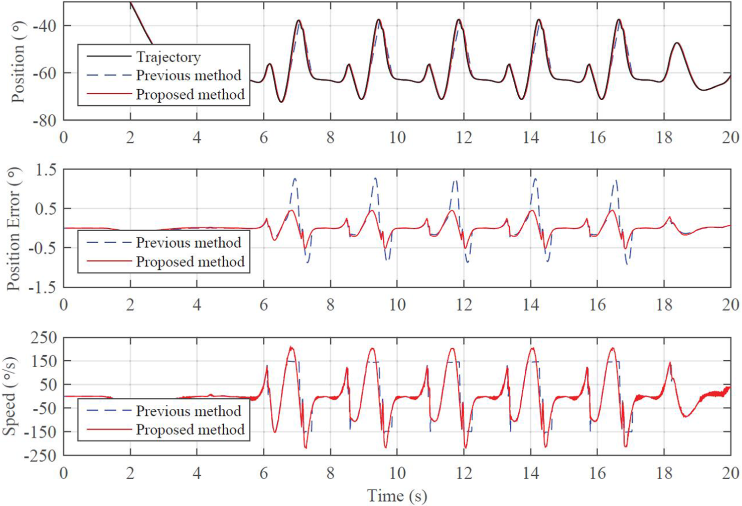
Impact motion of the knee joint during walking.
Conclusion and future work
This article presents how we developed the impact motion control system of the BHR-5 Humanoid Robot. The high power ability can be achieved by the proposed energy integral method of joint controller. In the design of the robots control system, a novel trajectory generation algorithm is developed. By these elements, the high performance impact motion is realized. The experiments demonstrate the high power ability of the robot. Future works including more high impact experiments such as running, jumping, weight lifting, or carrying weight are expected.
Footnotes
Academic Editor: Yong Chen
Declaration of Conflicting Interests
The author(s) declared no potential conflicts of interest with respect to the research, authorship, and/or publication of this article.
Funding
The author(s) disclosed receipt of the following financial support for the research, authorship, and/or publication of this article: This work was supported by the National High Technology Research and Development Program (863 Project) under Grant 2015AA042305 and 2015AA043202; the National Natural Science Foundation of China under Grants 61320106012, 61375103, 61273348, 61175077, and 60925014; the 111 Project under Grant B08043; the Key Technologies Research and Development Program under Grant 2015BAF13B01, 2015BAF10B02 and 2015BAK35B01; and the Beijing Natural Science Foundation under Grant 4154084.