
Abstract
Recently, an original innovative non-pillar coal mining technology was developed and widely implemented in China’s coal production based on this background. To explore the difference of stress field distributions between a novel non-pillar mining technique and two other current methods, different numerical models, that is, mining with gob-side entry retained by filling (GERFM), mining with roof cutting and pressure relief (RCPRM), and non-coal pillar mining with roadway formed automatically (RFANM), had been built based on the first industrial test of RFANM. The difference of the stress field distributions in those three types of mining patterns was studied and analyzed. The results showed that in front of the mining face, the influence of gob-side entry retaining method on stress distribution had a limited range. Due to the impact of roof cutting, the vertical stress of RCPRM was the minimum within the range of 0–10 m from the roadway, and it was the maximum within the range of 10–80 m. In the mining pattern of GERFM and RCPRM, the abutment stress was highly concentrated around the gate entry, and the stress-concentrated position of RCPRM was further than GERFM under the influence of roof cutting. However, there was no stress concentration in RFANM because the gate entry was canceled in this new mining pattern. At the side of mining face, the stress-concentrated position of GERFM was always located in the coal seam and was close to the roadway, whereas the stress-concentrated position of RFANM and RCPRM was located in the top layer which was deeper and higher than GERFM and was far away from the roadway. While the roadway was stable, the relationship between the peak value of the surrounding rock stress was GERFM > RCPRM and RFANM. According to the above laws, it was obtained that canceling early excavation was helpful to reduce the advance pressure in front of the working face, and roof cutting could cause the stress concentration zone to move away from the roadway. Thus, the stress of surrounding rock near the roadway was reduced, which was more beneficial to ensure the stability of the roadway.
Keywords
Introduction
Fossil energy is the cornerstone for human society development. As a nonrenewable resource, coal accounts for 61.8% 1 in the energy consumption structure. However, the coal mining rate of the traditional coal mining method is only 50%. With continuous development of technology and urgent demand of the international society for natural environment energy protection, finding a new coal mining method is urgently required. In the last decades, China government is putting efforts on the coordinated and unified development of the nature, economy and its society, and the mining industry is also exploring environmentally friendly coal production methods with high efficiency and safety. China is one of the first countries which exploit coal as the resource. In ancient times, the mining methods adopted by coal mines include roadway mining, skip lattice mining, cut mining, and room and pillar mining. 2 Earlier in the 18th century, the long-wall mining was first used in Shropshire, UK. As followed, the coal mines in Stafford, Derbyshire, and other shires began to use this mining method. 3 Prior to the first appearance of long-wall mining, some other mining methods were put into practice due to special geographical environment and engineering conditions, but two or more of such methods were combined in most cases.
In China, the first application of long-wall mining can be traced back to Zhongxing Coal Mine, Shandong (currently in Zaozhuang, Shandong) in the 1930s. 1 In the next periods, this mining method had been used in Chinese underground mining practice. To implement this mining method, a mining face is need to drive two gate entries, and a panel coal pillar is provided between two mining faces to reduce the impact of roof movement in gob on the gate entries of the adjacent mining face. The more extensive applications and the changes in production needs have further exposed the problems of this mining pattern, including heavy loss of coal pillar resources, high tunneling ratio of roadways, and tension of mining and tunneling continuance. 4
To solve the problems mentioned above, the Soviet Union began to explore the non-pillar mining techniques as early as in the 1930s. 5 At that time, the technological means for non-pillar mining was gob-side entry retained. More specifically, in the mining process on current mining face, erect supports with dense pillars, timber cribs, or god-side filling along the gob edges,6–8 retain the roadway in the previous panel at where it is and make it available for the adjacent mining face, so as to achieve the ends of canceling panel coal pillars and reduce roadway tunneling ratio.
Over five decades of development,9–12 the said mining with gob-side entry retained by filling (GERFM) with roadside supports has basically allowed for non-pillar mining. However, the dense roadside supports or the filled artificial pillars become subject to the pressure of roof pressure instead of coal pillars, leading to some hard problems, such as significant stress on the supporting structure, stress concentration of the filling body, and strong strata behaviors. 13
Since the 21st century, China has intensified its efforts to explore non-pillar mining techniques. In 2009, Chinese scholars proposed the gob-side entry retaining using roof cutting and pressure relief14,15 to eliminate the use of artificial fillers, which saves the cost of gob-side entry retaining to some extent; in addition, roof cutting can be used to improve the roof structure and its stress environment, thereby weakening the stress of surrounding rock to some extent, which would be more beneficial to stabilizing the gob-side entry retaining.
Based on this, in 2016, China further proposed a non-pillar mining method with no early gate entry excavation, that is, non-coal pillar mining with roadway formed automatically (RFANM).16,17 This method alters the roadway layout, mining, and excavation pattern that were previously used by the traditional pillar mining and the mining with gob-side entry retaining, allowing for the automatic formation of gate entry during the coal mining process, without setting panel coal pillar. The impact of excavation dynamic pressure on the gob-side entry retaining and of advance support pressure on the mining face will be eliminated due to cancelation of gate entry excavation, so that the stress environment of the surrounding rock will be further optimized.
As is known to all, underground pressure is the root cause of deformation even damage of surrounding rock during the mining activities. Thus, the distribution of stress field in the mining process is believed to be a key point that we must grasp. To date, the first industrial test trial of RFANM was completed in Ningtiaota Coal Mine, but the distribution characteristics of its stress field have not yet been reported. This work was set in the engineering background of the test mining face; a comparative analysis as to the distribution characteristics of stress field for existing three non-pillar mining methods was performed through numerical simulation, so as to reveal the similarities and differences of different mining methods with respect to the mining face and the stress distribution near the entry. Research findings are expected to provide a reference for control of surrounding rock and design of supports in the promotion and application of new techniques.
Existing three non-pillar mining methods
After the appearance of gob-side entry retaining, due to limitations on supporting theory, materials, and equipment, previous studies remained in the phase of field exploration, and there was no mature theoretical and technical system. To implement this mining method, a mining face is worked; only a gate entry needs to be driven with no need of setting entry protection pillar, as shown in Figure 1. Compared with traditional pillar mining methods, this technique reduces the excavation of gate entries by 50% and cancels the setup of panel coal pillars, which shows obvious advantages in terms of saving coal resources, reducing mining cost, and relieving tension of mining and tunneling continuance.

Schematic diagram of three non-pillar mining techniques: (a) GERFM, (b) RCPRM, and (c) RFANM.
Mining with roof cutting and pressure relief (RCPRM) was first proposed by Academician Manchao He in 2009 and its first test trial was successfully implemented in the same year in Baijiao Coal Mine, Sichuan.13,14 In contrast with previous GERFM, RCPRM forms a sidewall with the roof rock, with no need of filling concrete or high-water materials; the active roof cutting and pressure relief 18 not only eliminate the use of pillar and roadside filling, but also contribute to the stabilization of gate entry, and weaken the stress concentration of surrounding rock; its working principle is shown in Figure 1(b). Compared with traditional GERFM, this technique cancels the roadside filling and shows obvious advantages in reducing production cost, controlling uneven ground settlement, and relieving stress concentration of surrounding rock.
RFANM was first proposed by Academician Manchao He in 2016 and its industrial experimentation was successfully completed in Ningtiaota Coal Mine affiliated to Shaanxi Coal Industrial Company Limited in the next year.15,16 This innovative technique alters the roadway layout and mining pattern that are adopted by existing mining methods, allows for the automatic formation of a gate entry behind the mining face during the mining process, thereby canceling the gate entry excavation, its roadway layout is shown in Figure 1(c). Compared with traditional pillar entry mining, this technique reduces the excavation of gate entry by approximately 100% and cancels the setup of panel coal pillars. Compared with GERFM, it also cancels the gob-side entry retained by filling and shows more obvious advantages in reducing excavation cost and weakening local stress concentration of surrounding rock.
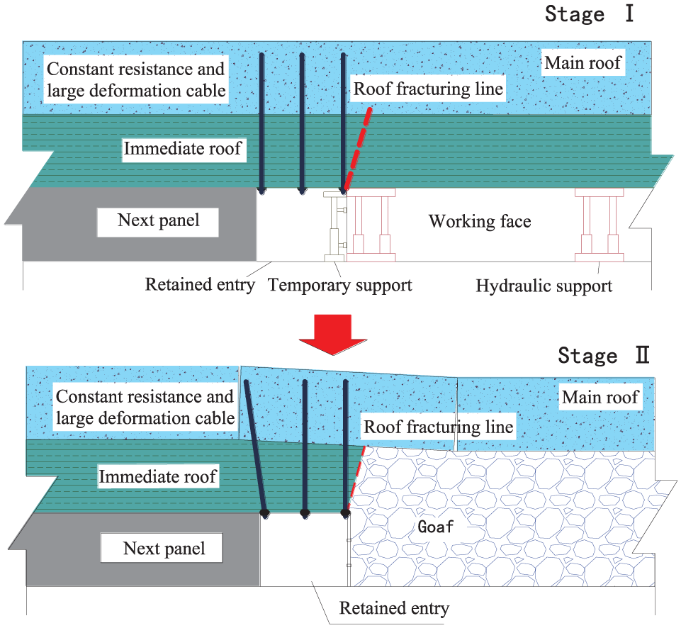
The technological process of the RFANM technique can be divided into the following two steps as shown in Figure 2: (1) stage I entry retaining construction, when the shearer cuts out the working space of roadway retaining, install the constant resistance and large deformation anchor cable to reinforce the retained entry roof, and conduct the roof cutting according to the roof fracturing line to cut off the connection between the roof of goaf and retained entry, then install temporary support to prevent the gangue from collapsing into retained entry; (2) stage II entry retaining formation, when the goaf roof collapse completely and the surrounding rock of retained entry is stable, the temporary support behind the working face can be removed and the entry is completely retained.
Process of the RFAMN technique.
Construction and analysis of numerical simulation model
Engineering background
For S1201-II mining face (experimentation mining face) of Ningtiaota Coal Mine, dip length of the working face is 280 m, strike length is 2344 m, average coal-seam thickness is 4.11 m, buried depth is 115–170 m, and the coal-seam dip angle is nearly horizontal. The basic roof of the mining face is medium-grained sandstone, with thickness of 5.4–21.5 m. The immediate roof is siltstone, with thickness of 0.78–4.05 m. The immediate floor is siltstone, with thickness of 1.8–16.3 m. The old floor is fine-grained sandstone, with thickness of 3.2–19.6 m, showing wavy bedding. The roadway layout of the mining face is shown in Figure 3, where the S1201-II tail entry is the roadway formed using RFANM in the mining process, and the geological histogram is shown in Figure 4.

Layout of working face and gate entries.

Geological histogram.
Construction of numerical simulation model
The numerical calculation model was constructed according to the engineering geological conditions of the S1201-II mining face, model dimensions: 400 m×400 m×70 m, as shown in Figure 5. A vertically downward force 3.0 MPa was applied on the upper boundary; the bottom boundary (i.e. the XOY plane with z = 0) was fixed in the z direction. The left and right boundaries (i.e. the XOZ plane with y = 0, y = 400) were fixed in the y direction. And the front and rear boundaries (i.e. the YOZ plane with x = 0, x = 400) were fixed in the x direction. For the simulated mining face, width is 280 m, coal-seam thickness is 4.0 m, and roadway size is 6.0 m×4.0 m. The bottom-up layout of the model roof is siltstone, with thickness of 2.0 m; medium-grained sandstone, with thickness of 14.0 m; overlying rock, with thickness of 30.0 m; the top-down layout of the model floor is siltstone, with thickness of 10.0 m; fine-grained sandstone, with thickness of 10.0 m.
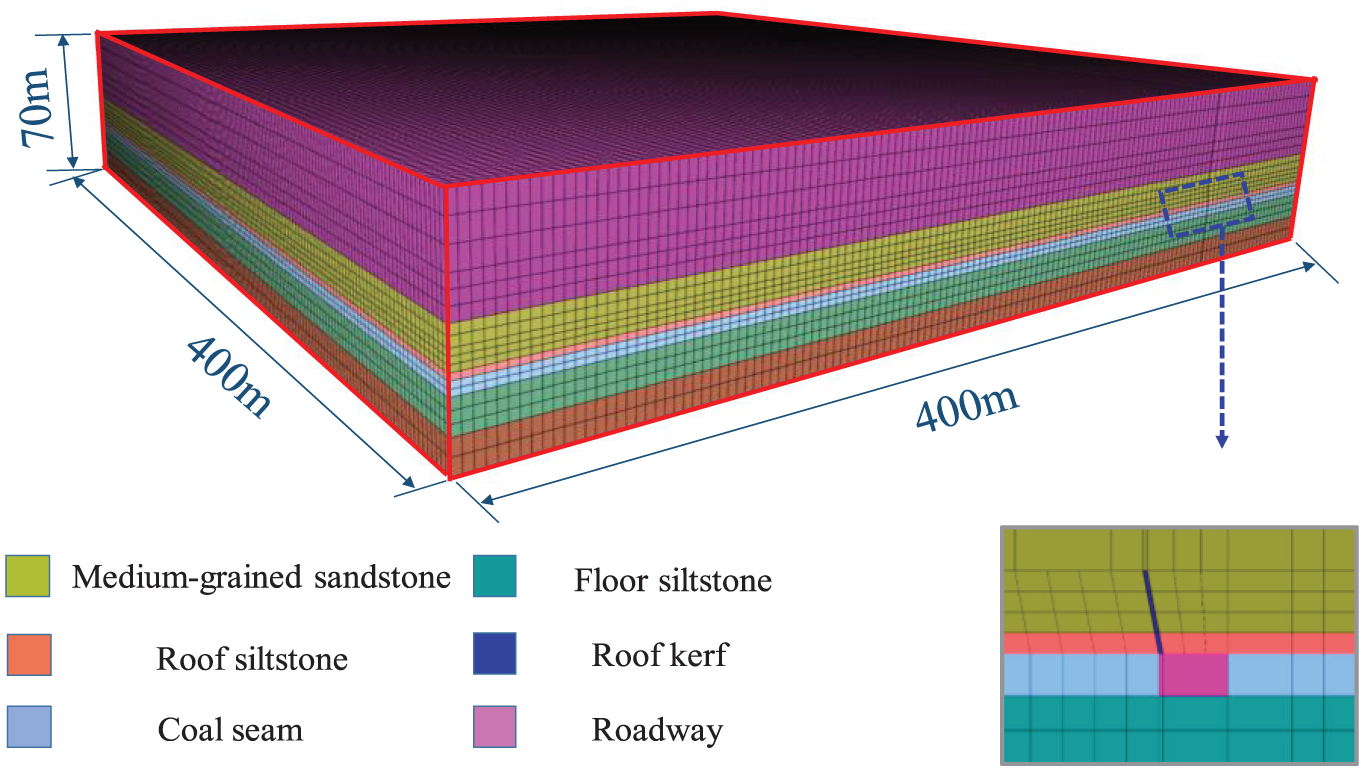
Numerical calculation model.
According to the technological process of three mining methods, different excavation schemes are formulated. The scheme for GERFM was first excavate two mining roadways in the model, after that mining the working face, and then filling the backfill body, finally extract the stress data. The scheme for RCPRM was first excavate two mining roadways in the model, and then roof cutting was conduct in the right roadway realized by Null command at predetermined position, after that mining the working face, finally the stress data were extracted. The scheme for RFANM was first excavate the left mining roadway in the model, and then mining the working face; at same time, Null command is carried out at the predetermined position on the right side of the working face to realize roof cutting, and the right roadway was retained; finally, the mining was completed, and the stress data were extracted.
Determination and verification of model parameters
According to the test results of physico-mechanical properties of the geological drilling hole core near the experimentation mining face, 19 the physico-mechanical parameters of the roof and floor rocks can be obtained, as given in Table 1. As is known to all, numerical simulation studies are often subject to the problem that it is difficult to select parameters. Furthermore, due to existence of cracks and structural faces, the strength of actual engineering rock mass is much less than that determined for the lab rock sample. 20 Therefore, before making calculation with the determined rock parameters, the parameters and simulation results of adjoining rocks were first verified according to the field measured data.
Physico-mechanical parameters of adjoining rocks.

During the mining process of RFANM, because there is no early gate entry excavation at the side of roadway formation, and the front abutment stress of this position cannot be monitored with existing equipment, the front abutment stress of one side of head entry was monitored during the experimentation process; the monitoring equipment is shown in Figure 6.

Layout of monitoring equipment for front abutment stress.
In Figure 6, the monitoring points a, b were at 5, 10 m inside the roadway coal sidewall, respectively; the monitoring result of Point a was taken and compared with the numerical simulation result obtained from the same position, as shown in Figure 7.

Verification result of model parameter.
As shown from Figure 7, the abutment pressures of the experimentation mining face began to significantly increase at about 20–30 m in front of the mining face and reached the maximum at 6–7 m in front of the mining face; the variations in the simulation result in respect of the vertical stress were almost the same with the field measured result. It was thus thought that the selected model and parameter can meet the reliability requirement of the numerical simulation to some extent.
Analytical method of numerical simulation
Based on the above numerical calculation model, the mining process was simulated according to the mining face and roadway layout of RFANM, RCPRM, and GERFM, where the boundary conditions of the model, length of mining face, and roadway section dimensions were the same, as shown in Figure 8.

Layout of monitoring lines for numerical simulation analysis: (a) RFANM, (b) RCPRM, and (c) GERFM.
Figure 8 shows the vertical stress distribution patterns on the interface between the coal seam and the roof with different mining techniques. According to the simulation results, nine monitoring lines were arranged on the face as shown in the patterns, in which Lines 1, 2, 3 were in front of the mining face, as perpendicular to the direction of the mining face; Lines 4, 5, 6 were at 20, 10, 5 m in front of the mining face, respectively, as parallel to the direction of the mining face; Lines 7, 8, 9 were at 10, 50, 100 m behind the mining face, as parallel to the direction of the mining face. To analyze the results, every monitoring line was vertically sectioned to generate the vertical stress patterns for each section, and then the vertical stress data on every monitoring line was extracted to draw the stress curves. Next, the stress distribution in front of the mining face and of the same position at one side for the four mining methods was compared and analyzed, so as to obtain the stress field distribution characteristics.
Stress distribution characteristics in front of the mining face
Stress distribution characteristics in the direction of face advance
Monitoring Line 1 was in front of the mining face and at the side of the head entry, as perpendicular to the direction of the mining face, at 5 m from the inner sidewall of the head entry, its vertical stress distribution patterns and stress distribution curves are shown in Figure 9.

(a) Vertical stress distribution on the vertical section and (b) vertical stress distribution curves of Monitoring Line 1.
Statistical results of peak vertical stress values and positions of Monitoring Line 1 are given in Table 2. As mentioned earlier, the vertical stress distribution in respect of the three mining methods was basically consistent. As the distance from the mining face increases, the vertical stress value tended to increase first and then decrease; the stress distribution curves of Monitoring Line 1 in respect of the three mining methods were fully overlapped, with the same peak stress values and with the same positions from the entry, which indicates that the differences in entry retaining patterns had no impact on the stress distribution of the other side of the mining face.
Peak vertical stress of Monitoring Line 1.

RFANM: non-coal pillar mining with roadway formed automatically; RCPRM: mining with roof cutting and pressure relief; GERFM: mining with gob-side entry retained by filling.
Monitoring Line 2 was located in the middle part of the mining face and its vertical stress distribution patterns and stress distribution curves are shown in Figure 10.

(a) Vertical stress distribution on the vertical section and (b) vertical stress distribution curves of Monitoring Line 2.
Statistical results of peak vertical stress values and positions of Monitoring Line 2 are given in Table 3. As mentioned earlier, the vertical stress distribution in respect of the three mining methods was also basically consistent; the stress distribution curves of Monitoring Line 2 were fully overlapped, which indicates that the differences in roadway retained patterns also had no impact on the stress distribution of the middle part of the mining face.
Peak vertical stress of Monitoring Line 2.

RFANM: non-coal pillar mining with roadway formed automatically; RCPRM: mining with roof cutting and pressure relief; GERFM: mining with gob-side entry retained by filling.
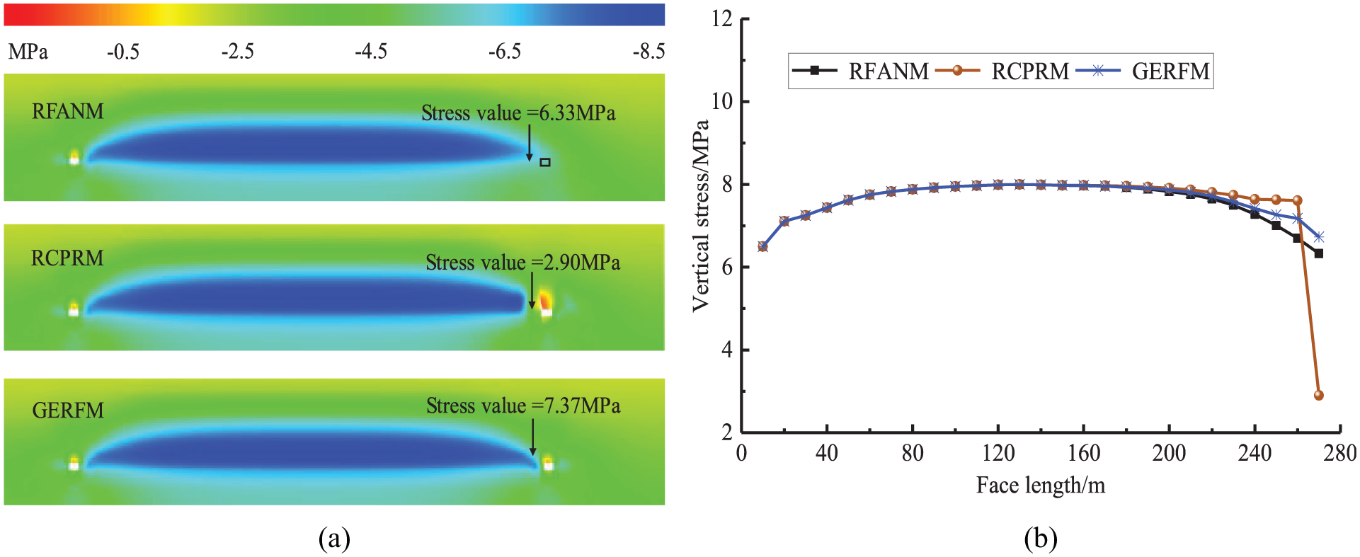
Monitoring Line 3 was located in front of the mining face and at the side of the tail entry (at the side of the entry retained), 5 m from the inner sidewall of the tail entry, and its vertical stress distribution patterns and stress distribution curves are shown in Figure 11.
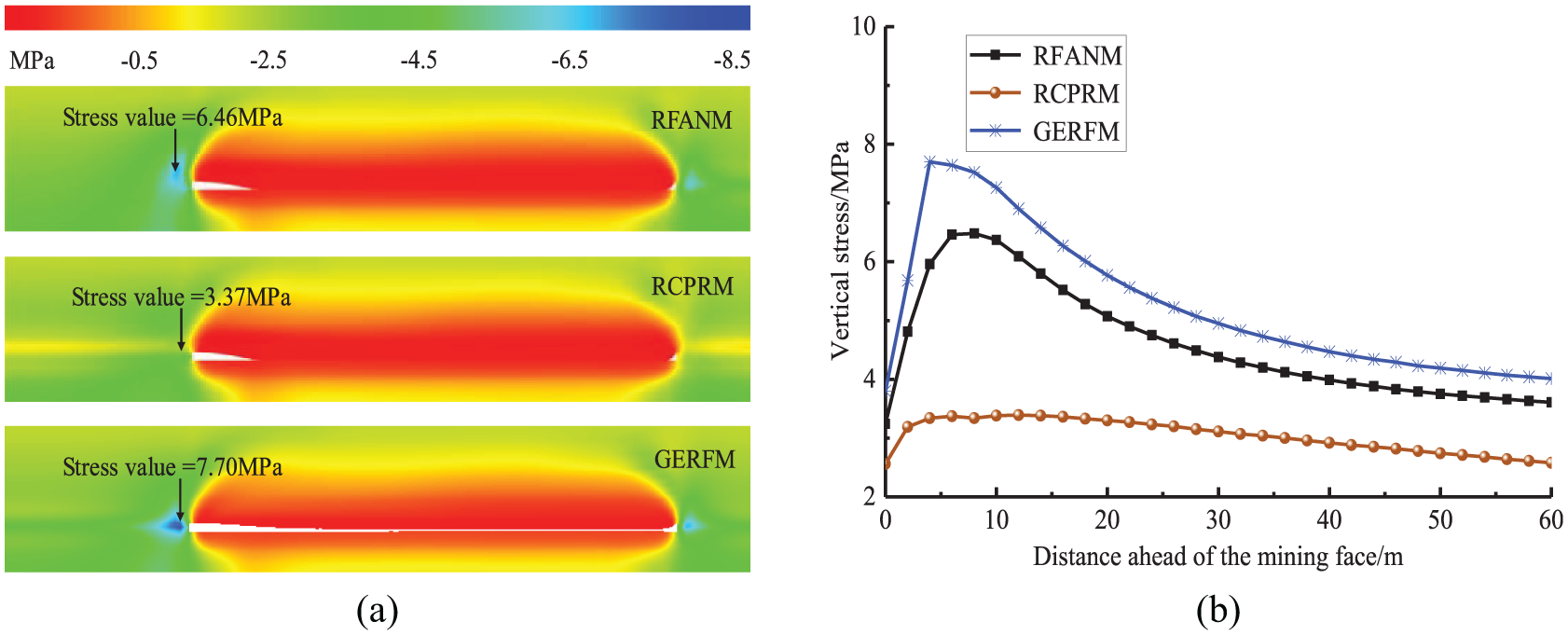
(a) Vertical stress distribution on the vertical section and (b) vertical stress distribution curves of Monitoring Line 3.
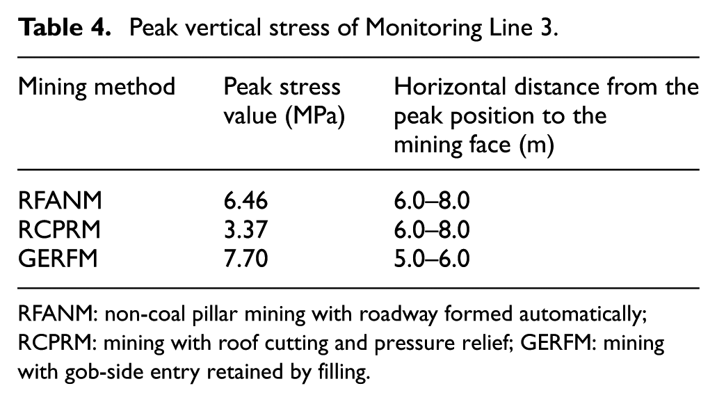
Statistical results of the peak vertical stress values and positions of Monitoring Line 3 are given in Table 4. As mentioned earlier, within a certain range in front of the mining face, the vertical stress values can be arranged in a descending order as GERFM > RFANM > RCPRM. This indicates that there was no early roadway excavation at the entry retained side on the RFANM mining face, so it was not subject to the impact of stress superposition induced by entry excavation, with relatively low stress concentration. However, there was advance entry excavation at the entry retained side on the RCPRM and GERFM, but the vertical stress on the former face was much lower than that on the latter one. To explain this clearly, the RCPRM practice pre-cuts the entry roof in front of the mining face, so that the stress concentration near the roadway was transferred to a deeper position, while Monitoring Line 3 was right in the low-stress range.
Peak vertical stress of Monitoring Line 3.
RFANM: non-coal pillar mining with roadway formed automatically; RCPRM: mining with roof cutting and pressure relief; GERFM: mining with gob-side entry retained by filling.
Stress distribution characteristics along the length direction of the mining face
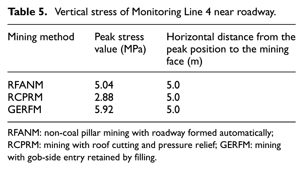
Monitoring Line 4 was located at 20 m in front of the mining face and as parallel to the length direction of the mining face; its vertical stress distribution patterns and stress distribution curves are shown in Figure 12.

(a) Vertical stress distribution on the vertical section and (b) vertical stress distribution curves of Monitoring Line 4.
Statistical results of the vertical stress values near the roadway at 20 m in front of the mining face are given in Table 5. As mentioned earlier, the stress distribution characteristics at 20 m in front of the mining face for the three mining methods can be described as: at 0–200 m from the head entry, the stress distribution curves were basically overlapped, while it showed certain differences at 0–80 m from the tail entry (at the roadway retained side). In which, at 0–10 m from the roadway retained, the vertical stress values can be arranged in a descending order as GERFM > RFANM > RCPRM. At 10–80 m from the roadway retained, the front abutment pressure of RFANM was the least, while the vertical stress value of RCPRM within this range was surprisingly greater than that of the other two mining methods, because its stress concentration was transferred to a deeper position.
Vertical stress of Monitoring Line 4 near roadway.
RFANM: non-coal pillar mining with roadway formed automatically; RCPRM: mining with roof cutting and pressure relief; GERFM: mining with gob-side entry retained by filling.
Based on the preliminary analysis, under the mining conditions of GERFM, early roadway excavation will redistribute the stress on surrounding rock near the roadway, resulting in an increase in the stress on surrounding rock within a certain range of distance from the roadway. In contrast, under the mining conditions of RCPRM, although there was early gate entry excavation in front of the mining face as well, the roof cutting will disconnect the relationship between the gob-side roof and the roadway roof within a certain range, so the ground pressure can only be transmitted by a higher layer of roof, resulting in an decrease in the stress on surrounding rock within a certain range of distance near from the roadway, the zone where the stress increases will be transferred to a deeper position, resulting in a stress increase of RCPRM at 5–80 m from the roadway retained. Under the mining conditions of RFANM, there was no early roadway excavation in front of the mining face and no roof cutting was performed, so its stress value near the roadway retained was between the values of the other two mining methods. Monitoring Line 5 was located at 10 m in front of the mining face and its vertical stress distribution patterns and stress distribution curves are shown in Figure 13.
(a) Vertical stress distribution on the vertical section and (b) vertical stress distribution curves of Monitoring Line 5.
Statistical results of the vertical stress values near the roadway at 10 m in front of the mining face are given in Table 6. Under the mining conditions of the three mining methods, the abutment pressure values at 10 m in front of the mining face are greater than that at 20 m; at 0–10 m from the roadway, the vertical stress values can be arranged in a descending order as GERFM > RFANM > RCPRM, and its distribution rule was basically consistent with that at 20 m in front of the mining face.
Vertical stress of Monitoring Line 5 near roadway.

RFANM: non-coal pillar mining with roadway formed automatically; RCPRM: mining with roof cutting and pressure relief; GERFM: mining with gob-side entry retained by filling.
Monitoring Line 6 was located at 5 m in front of the mining face, as parallel to the length direction of the mining face, and its vertical stress distribution patterns and stress distribution curves are shown in Figure 14.

(a) Vertical stress distribution on the vertical section and (b) vertical stress distribution curves of Monitoring Line 6.
Statistical results of the vertical stress values near the roadway at 5 m in front of the mining face are given in Table 7. Under the mining conditions of GERFM, the stress concentration was obvious at 5 m in front of the mining face. To explain this through preliminary analysis, during the mining process of GERFM, the stress redistribution would occur near the gate entry due to roadway excavation, resulting in an increase in local stress in the surrounding rock, when it was superposed with the front abutment pressure of the mining face, this position will be vulnerable to stress concentration, resulting in the deformation of the roadway. However, there was early gate entry excavation in front of the RCPRM mining face as well, but its stress significantly decreased at this position. To explain this clearly, the RCPRM method pre-cuts the lane roof in front of the mining face, so that the stress concentration near the roadway was transferred to a deeper position, while the range of about 10 m from the roadway was in the low-stress range.
Vertical stress of Monitoring Line 5 near roadway.

RFANM: non-coal pillar mining with roadway formed automatically; RCPRM: mining with roof cutting and pressure relief; GERFM: mining with gob-side entry retained by filling.
Based on the above-described findings, the following rules can be summarized:
For these three non-pillar mining methods, in front of and as perpendicular to the mining face, as the distance from the mining face increased, the vertical stress distribution characteristics tended to first increase and then decrease.
In front of and as parallel to the mining face, the impact of the entry retaining patterns on stress distribution has a limited range; subject to the impact of roof cutting, this range can be further divided into two parts: within the impact range of cutting, the vertical stress values can be arranged in a descending order as RCPRM > GERFM > RFANM; beyond the impact range of cutting, it can be arranged as RFANM > RCPRM > GERFM.
In front of the mining face, under the mining conditions of RCPRM and RFANM, there was a certain degree of stress concentration near the roadway. Comparatively, the position of stress concentration in the latter is more inward than that in the former. Through preliminary analysis, this can be attributed to the superposition of gate entry excavation and front abutment pressure. Because the GERFM cancels the early roadway excavation, there was no obvious stress concentration.
These findings indicate that canceling early excavation is beneficial to reduce the front abutment pressure within a certain range in front of the mining face; in addition, roof cutting will promote the transfer of stress concentration zone to a position that is away from the roadway, resulting in a decrease in the surrounding rock stress near the roadway, which will be more beneficial for stabilizing the roadway.
Lateral stress distribution characteristics of the mining face
Lateral stress distribution characteristics in front of the mining face
Lateral distribution curves of the vertical stress on the monitoring lines at 20 m, 10 m, 5 m in front of the mining face are shown in Figure 15.

Vertical stress distribution curves of monitoring lines (lateral): (a) Monitoring Line 4, (b) Monitoring Line 5, and (c) Monitoring Line 6.
As shown in Figure 15, under the mining conditions of GERFM and RCPRM, subject to the impact of advance roadway excavation, the peak stress was inside the sidewall, so the stress tended to first increase and then decrease from the coal wall to the inside, the peak lateral stress in front of the mining face was always in the coal body, and the peak vertical stress of GERFM was greater than that of RCPRM, and its distance from the roadway sidewall was also closer. Under the mining conditions of RFANM, the peak stress was always at the edge of the pre-set roadway; the stress gradually decreased from this position to the inside of coal body, which indicates that with this mining method, the range in front of the mining face was less subject to mining activities; the surrounding rock was not damaged, which is more beneficial to ensure its integrity and stabilization.
Lateral stress distribution characteristics behind the mining face
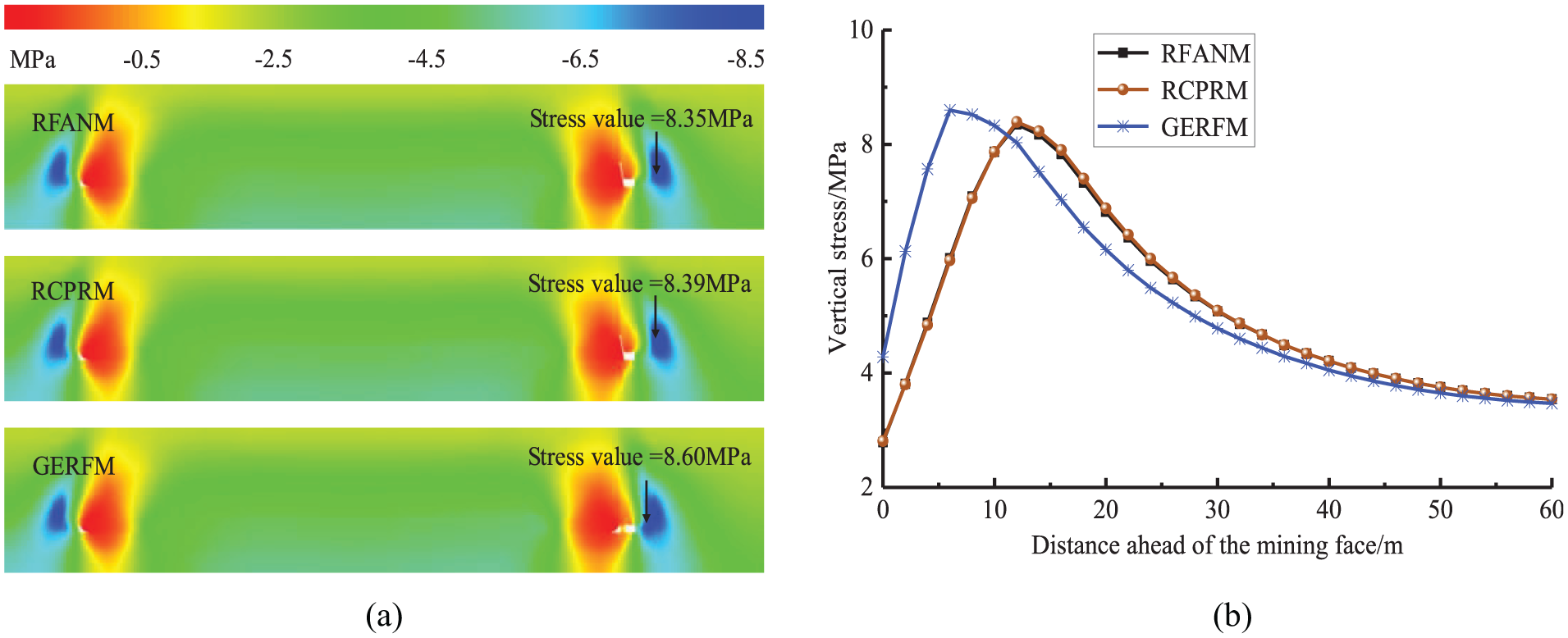
Monitoring Line 7 was located at 10 m behind the mining face and its vertical stress distribution patterns and stress distribution curves are shown in Figure 16.

(a) Vertical stress distribution on the vertical section and (b) vertical stress distribution curves of Monitoring Line 7.
Statistical results of the peak stress values and positions at 10 m behind the mining face are given in Table 8. As shown from the above patterns, the stress distribution characteristics for the three mining methods can be described as follows: (1) the stress values tended to first increase and then decrease from the coal wall to the inside, and the lateral peak stress values on the mining face were inside the sidewall; (2) the peak stress values can be arranged in a descending order as GERFM > RCPRM > RFANM, in which the peak stress value for RFANM was about 12.9% lower than that for GERFM; (3) The peak value for GERFM was in the coal seam, the peak position was the nearest to the sidewall (about 6.0 m), and the peak values for RFANM and RCPRM were in the roof above the coal seam, which was farther from the roadway.
Peak vertical stress of Monitoring Line 7.

RFANM: non-coal pillar mining with roadway formed automatically; RCPRM: mining with roof cutting and pressure relief; GERFM: mining with gob-side entry retained by filling.
Through preliminary analysis, under the mining conditions of GERFM, subject to the impact of lateral pressure of stope, there was obvious stress concentration in the sidewall near the lane. Under the mining conditions of RFANM and RCPRM, although the lateral stress concentration of stope will also occur, roof cutting disconnected the relationship between the god-side roof and the roadway roof within a certain range. Under this circumstance, the underground pressure had to be transferred by relying on the higher level roof, so the stress concentration will be transferred to a deeper position, so that the stress concentration zone occurred in the roof strata that is farther from the roadway. Monitoring Line 8 was located at 50 m behind the mining face and its vertical stress distribution patterns and stress distribution curves are shown in Figure 17.

(a) Vertical stress distribution on the vertical section and (b) vertical stress distribution curves of Monitoring Line 8.
Statistical results of the peak stress values and positions at 50 m behind the mining face are given in Table 9. As shown from the above patterns, the stress values for the three mining methods were significantly higher than the position at 10 m behind the mining face; the peak stress values can be arranged in the same order as GERFM > RCPRM > RFANM, in which the peak stress value for RFANM was about 6.5% lower than that for GERFM. Stress distribution curves for RFANM and RCPRM were basically overlapped, and the distances from the peak stress position to the sidewall were 12 m. This suggests that at a certain position behind the mining face, roof movement was basically stopped. Under this circumstance, the stress distribution for RFANM and RCPRM with the same roof cutting characteristics tended to be consistent.
Peak vertical stress of Monitoring Line 8.

RFANM: non-coal pillar mining with roadway formed automatically; RCPRM: mining with roof cutting and pressure relief; GERFM: mining with gob-side entry retained by filling.
Monitoring Line 9 was located at 100 m behind the mining face and its vertical stress distribution patterns and stress distribution curves are shown in Figure 18.
(a) Vertical stress distribution on the vertical section and (b) vertical stress distribution curves of Monitoring Line 9.
Statistical results of the peak stress values and positions at 100 m behind the mining face are given in Table 10. As shown from the above patterns, the stress distribution characteristics for the three mining methods can be described as follows: (1) the stress values for the three mining methods were higher than that at 50 m behind the mining face, but the rate of increase significantly decreased; (2) the peak stress values can be arranged in a descending order as GERFM > RCPRM > RFANM, compared with positions nearer to the mining face, the peak stress values for the three mining methods were closer; (3) the peak stress value for GERFM was still in the coal seam, the range of stress concentration was further expanded to a certain extent, the distance from the peak stress position to the sidewall was still 6.0 m; the peak stress values for RFANM and RCPRM were in the roof above the coal seam, and the stress distribution curves of the two methods were basically overlapped, the distances from the peak stress position to the sidewall were 12 m, and there was no obvious transfer of the peak position.
Peak vertical stress of Monitoring Line 9.

RFANM: non-coal pillar mining with roadway formed automatically; RCPRM: mining with roof cutting and pressure relief; GERFM: mining with gob-side entry retained by filling.
Based on the above-described findings, the following rules can be summarized:
At the side of the mining face, the stress concentration position for GERFM was always in the coal seam and was nearer to the roadway; the stress concentration positions for RFANM and RCPRM were in the roof strata at the deeper coal wall of roadway, which were farther from the roadway.
At the side of the mining face, the peak stress values can be arranged in a descending order as GERFM > RCPRM > RFANM; after the gob-side roof became stabilized, the stress distribution curves for RCPRM and RFANM were basically overlapped.
At the side of the mining face, the distances between the peak stress zone and the roadway can be arranged in an ascending order as GERFM < RCPRM < RFANM.
These findings show that roof cutting will promote the transfer of the gob-side lateral stress concentration zone to a deeper and higher position, so that the surrounding rock of roadway was in the low-pressure zone, contributing to the stabilization of the roadway.
Conclusion
Along the advance direction of the mining face, the front abutment pressure for existing three non-pillar mining methods tended to first increase then decrease, the peak stress was generally at 6–10 m in front of the mining face. In which, the stress distributions in the middle part of the mining face and at the non-roadway retained side were basically consistent, and the stress values near the roadway retained can be arranged in a descending order as GERFM > RFANM > RCPRM.
In front of and as parallel to the mining face, subject to the impact of entry retaining patterns, this range can be further divided into two parts: within the impact range of cutting, the vertical stress values can be arranged in a descending order as RCPRM > GERFM > RFANM; beyond the impact range of cutting, it can be arranged as RFANM > RCPRM > GERFM.
At the side of the mining face, the peak stress values can be arranged in a descending order as GERFM > RCPRM > RFANM, and the distances between the peak stress zone and the roadway can be arranged in an ascending order as GERFM < RCPRM < RFANM.
These findings indicate that canceling early excavation is beneficial to reduce the front abutment pressure within a certain range in front of the mining face; in addition, roof cutting will promote the transfer of stress concentration zone to a position that is away from the roadway, resulting in a decrease in the surrounding rock stress near the roadway, which will be more beneficial for stabilizing the roadway.
Footnotes
Handling Editor: James Baldwin
Author contributions
All the authors contributed to this paper. M.H. conceived and designed the research. E.Z. and Y.W. performed the theoretical analysis. J.Y. provided theoretical guidance in the research process.
Declaration of conflicting interests
The author(s) declared no potential conflicts of interest with respect to the research, authorship, and/or publication of this article.
Funding
The author(s) disclosed receipt of the following financial support for the research, authorship, and/or publication of this article: This work is supported by the National Program on Key Basic Research Project (973 Program) (no. 2016YFC0600900) and the National Natural Science Foundation of China (no. 51674265), which are gratefully acknowledged.