
Abstract
When gob side entry retaining is carried out in backfill mining, the roof will show different subsidence morphology due to the difference of compactness and supporting force of the backfill body at different positions. This paper analyzed the immediate roof subsidence structure under two extreme conditions, constructed the roof segmented subsidence structure and the mechanical model of roadside backfill body, and used FLAC3D software to investigate the roof migration and the force law of the roadside backfill body under the conditions of different goaf backfilled rates, different width and strength of roadside backfill body. Finally, the backfill practice of a mine in Shandong Province of China is taken as an example for analysis. The results show that the segmented subsidence structure of the immediate roof is related to the mechanical properties of the roadside backfill body and the goaf backfill body. When the backfilled rate of goaf decreases from 95% to 70%, the width of roadside backfill body decreases from 5 m to 1 m, and the elastic modulus decreases from 10 GPa to 0.5 GPa, the greater difference in the subsidence and inclination of the immediate roof on both sides of the roadside backfill body is, the more obvious the segmented subsidence structure characteristics of the immediate roof are, and the greater force on the roadside backfill body will be, the more unfavorable it is to maintain the stability of the roadway surrounding rock and the roadway backfill body. Therefore, when gob side entry retaining is carried out in backfill mining, the surrounding rock structure and the force on roadside backfill body should be considered comprehensively.
Introduction
As a non-pillar mining technology, gob side entry retaining has significant advantages such as high coal recovery rate and less roadway excavation amount, which is widely used in mines with traditional caving method (Liu et al., 2020; Zhang et al., 2012; Zhou et al., 2012). In recent years, solid backfill mining technology has been rapidly developed and applied in the construction of green mines due to its good roof control effect, significant surface subsidence reduction effect and high comprehensive benefits (Balat, 2007; Fan et al., 2014; Miao et al., 2008). So retaining roadway along the backfilling area combines the two advantages of backfill mining and gob side entry retaining and can achieve multiple effects (Huang et al., 2011).
The surrounding rock structure and deformation characteristics of gob side entry retaining in backfill mining are different from those of gob side entry retaining by caving method (Kang et al., 2011). Many scholars have done a lot of researches on the surrounding rock structure and deformation of gob side entry retaining in backfill mining. Miao et al. (2020) analyzed the influence of large deformation of roadway retained in backfill mining, established the structural mechanical model of the retained roadway under thick and hard roof, pointed out the relationship between the backfilled rate of goaf and roof subsidence of retained roadway, and put forward countermeasures to control large deformation of the retained roadway. Sun et al. (2020) analyzed the structural features of the surrounding rock in gob-side entry and builds a mechanical damage model for gob-side supporting based on the hypothesis of planar slip surface in the theory of Coulomb earth pressure. Ju et al. (2015) took a mine in Jining as the engineering background, proposed the concept of a collaborative control system for backfilling mining and retaining roadway, and determined the influencing factors of roadway surrounding rock stability by numerical simulation. Ma et al. (2011) established a mechanical model for the key stratum of gob side entry retaining under the conditions of backfilling and fully-mechanized coal mining technology, adopted Coulomb’s earth pressure theory to solve the problem of lateral pressure of the gangue backfilling area on the supporting wall beside the roadway. Based on the movement characteristics of the overlying strata, Quan et al. (2018) established an immediate roof mechanical model of gob side entry retaining in backfill mining, deduced the formula for the width of the roadside backfill body and the length of the elastoplastic zone in the coal bank, and conducted an engineering example analysis. Xie et al. (2014) based on the mining pressure phenomena such as support system damage that occurred in gob-side retaining entries of deep backfilling with large mining height, put forward an integrated control technology consisting of high-water material backfill body performance optimization, collaborative support system with powerful rockbolts and cables and combined steel bar-concrete brackets, and discussed its mechanism. Although many scholars (Gong, 2018; Li et al., 2019; Yang et al., 2015; Yin et al., 2017; Wang et al., 2018; Wu et al., 2019) have done a lot of research on the surrounding rock structure and deformation of gob side entry retaining in backfill mining, in the actual project, due to the different bearing capacity and compressibility between the roadside backfill body and the goaf backfill body, the immediate roof subsidence on both sides of the roadway backfill body is different, showing a segmented structural characteristic. At present, there is little literature on this structure in-depth study.
In this paper, the immediate roof subsidence structure under two extreme conditions is analyzed, the roof segmented subsidence structure and the mechanical model of roadside backfill body are constructed, the roof segmented subsidence structure and the force law of the roadside backfill body under different conditions are studied. Finally, the backfilling practice of a mine in Shandong Province of China is taken as an example for analysis. The research results provide a reference for the engineering practice of backfill mining and retaining roadway.
The migration model of immediate roof
Different from the in-situ gob side entry retaining technology (Huang et al., 2011), retaining roadway along the backfilling area is to fill the goaf with solid wastes such as gangue and fly ash, and then grouting is used to reinforce the backfill body within a certain width at the edge of the backfilling area, so that it can be cemented to form a roadside backfill body with a certain bearing capacity and stability, which can meet the ground pressure behavior while achieving the purpose of economically and effectively supporting the roof to maintain the roadway. The schematic diagram of the retaining roadway along the backfilling area is shown in Figure 1.
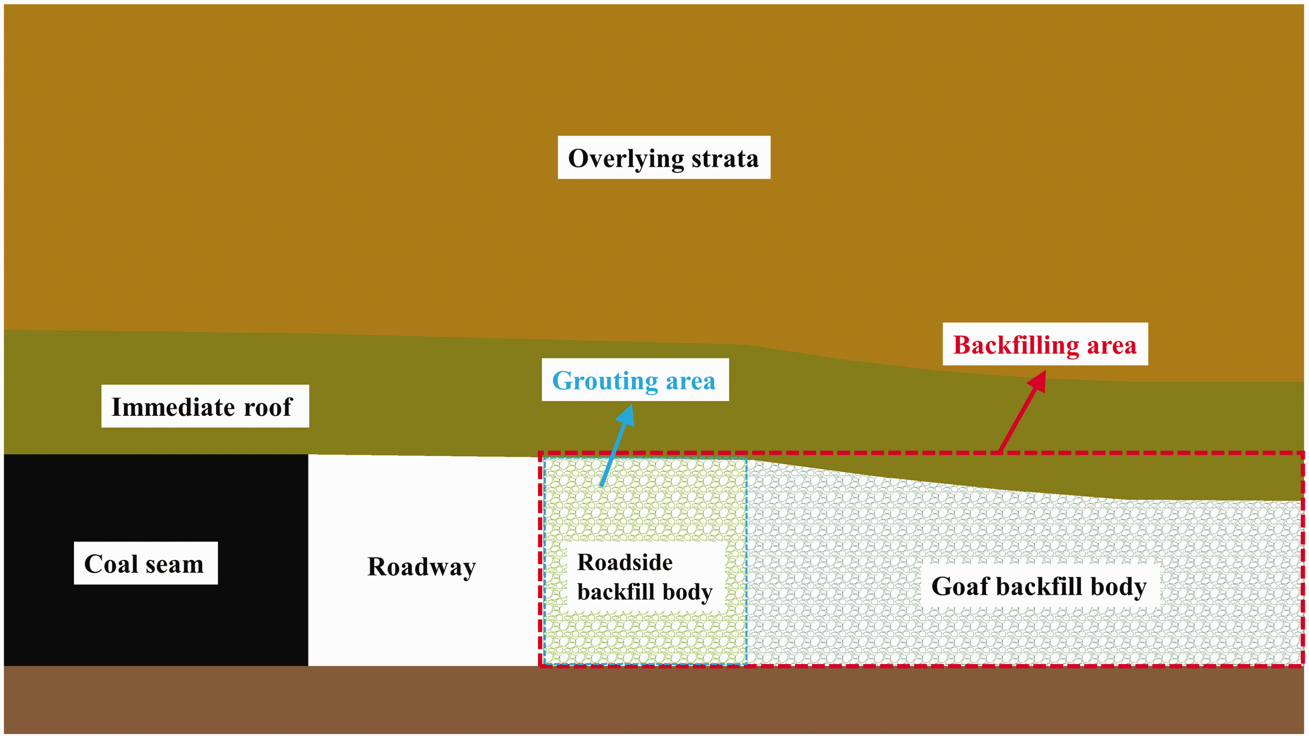
The schematic diagram of retaining roadway along the backfilling area.
In the project of retaining roadway along the backfilling area, the roadside backfill body is closely connected with the goaf backfill body and controls the roof cooperatively. However, they are independent due to different strength and compressibility in the process of roof subsidence, forming two supporting structures of roadside backfill body and goaf backfill body.
Generally speaking, there are two extreme cases for the support strength and compressibility of the roadside backfill body: If the mechanical properties of the roadside backfill body and the goaf backfill body are not significantly different, the roof will compress the roadside backfill body and the goaf backfill body together during the subsidence process until the resistance of the goaf backfill body reaches the balance with the overburden load, the compression amount of the roadside backfill body is basically the same as that of the goaf backfill body, as shown in Figure 2(a). In this case, the initial strength of roadside backfill body is usually not high, on the one hand, it is unable to resist the lateral pressure exerted on the roadside backfill body during the compression process of goaf backfill body, on the other hand, the compression amount of the roadside backfill body is too large, which is difficult to maintain its integrity and stability without damage and collapse during the continuous subsidence of the roof in reality. Even if the roadside backfill body still has a certain residual support strength after compression, the excessive compression amount will not only lead to the reduction of roadway section, affect the ventilation and pedestrian and so on, but also may cause the roof to break and cut off, increase the rib fall of coal wall and other safety hazards. If the support strength of the roadside backfill body is very high, it can fully support the maximum overlying load and resist the peak value of ground pressure in the process of backfilling mining. Under this condition, the compression amount of roadside backfill body is very small, or even no compression. The support structure will be transformed from the previous structure with the coal seam as the support to the load-bearing structure with the coal seam and roadside backfill body as common support. The subsidence morphology of the immediate roof starting from the coal wall will change into the subsidence morphology starting from the roadside backfill body. The roof subsidence only occurs in goaf, as shown in Figure 2(b). This situation will inevitably lead to concentrated stress on the roadside backfill body, and the internal storage energy is too high. Once a slight disturbance or crack occurs, the roadside backfill body will be suddenly unstable failure, which will have a strong impact on the roadway, resulting in sudden roof cutting off or collapse, which is a great potential safety hazard. Moreover, the excessive strength of roadside backfill body will lead to material waste and high cost.
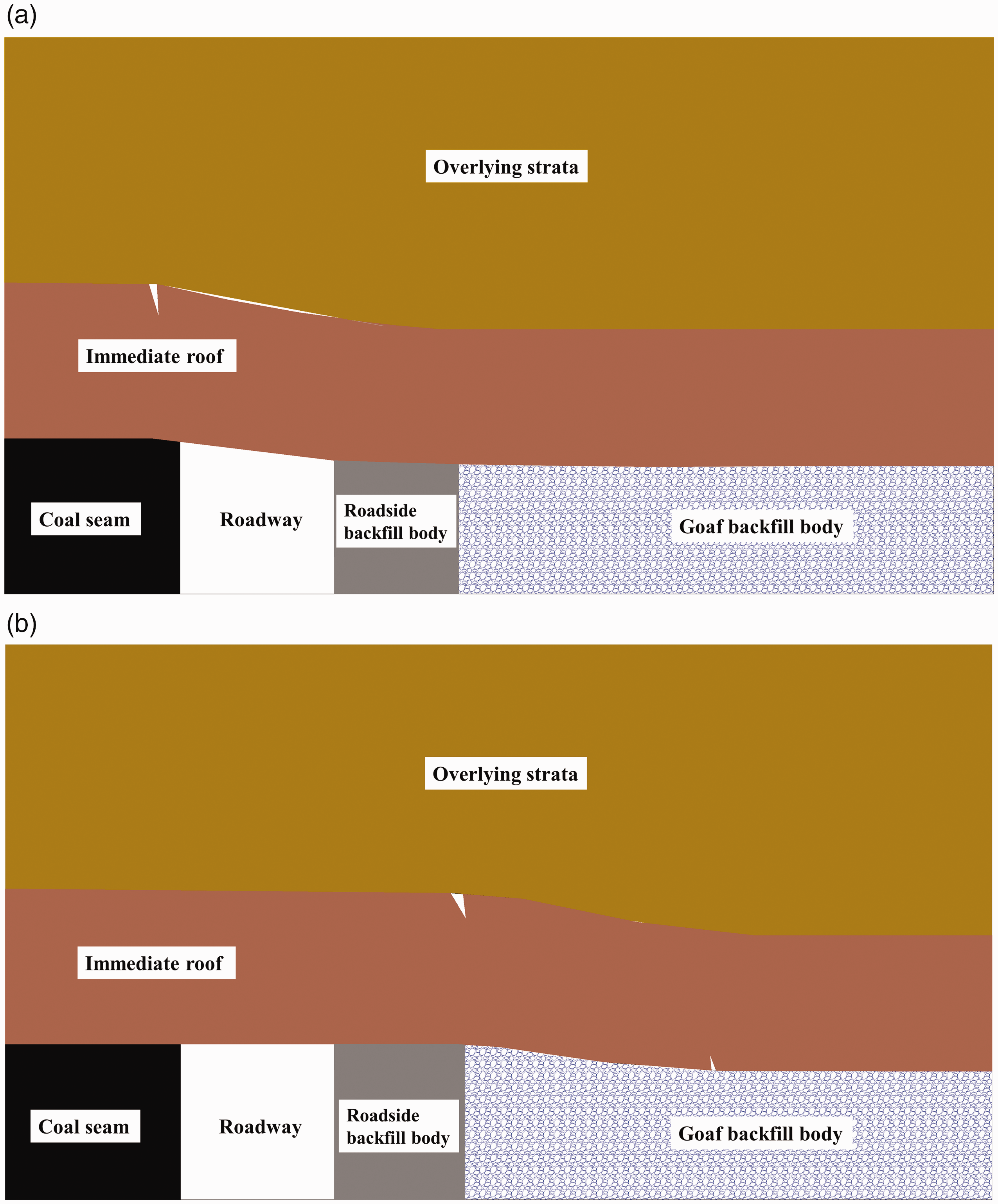
Two extreme cases of the immediate roof migration model. (a) Immediate roof migration model under limit compression and (b) immediate roof migration model without compression.
The strength and compression of the roadside backfill body should be between the two extreme cases in backfill mining, that is, the compressive strength of the roadside backfill body should be sufficient to support the overlying load and the peak value of ground pressure. Moreover, it should have the appropriate compression amount. The compression amount should not be too small or too large, so that the roadside backfill body can maintain its independence, stability and integrity. The roadside backfill body and goaf backfill body should work together to support and control the roof, effectively maintaining the roadway section. In this case, the immediate roof subsidence is not synchronous at the position of roadside backfill body and goaf, thus forming a segmented structure.
Theoretical analysis of segmented subsidence structure with immediate roof
Displacement analysis
It can be seen from the above analysis that, under the background of retaining roadway along the backfilling area, the strength and compressibility of the roadside backfill body and goaf backfill body are different, which leads to the different supporting effect of the backfill body on the roof, so the subsidence morphology of the immediate roof is different, showing a segmented structural characteristic, as shown in Figure 3. After the goaf is filled, the roof beam will subsidence and deform under the action of overlying load, and the plastic zone of the coal wall with the width of La appears at the coal seam, where the immediate roof has a slight subsidence. In the position of the roadside backfill body, the roof compresses the roadside backfill body, and the roadside backfill body also resists the overlying strata subsidence, until the supporting strength of the roadside backfill body reaches the balance with the subsidence pressure of overlying strata. The span and subsidence of the roof are small at this stage, which can be regarded as the linear subsidence of the roof, and the subsidence angle with the horizontal plane is θ1. In the same way, at the position of the goaf, after the interaction between the roof and the goaf backfill body reaches an equilibrium state, a compression zone and a compaction zone of the backfill body are formed along the goaf inclination. The supporting effect of the goaf backfill body is far less than that of the roadside backfill body, and it has greater compressibility, therefore, the immediate roof in goaf presents an obvious subsidence morphology, and the subsidence angle θx formed by the immediate roof and the horizontal plane is related to the deflection of the immediate roof.
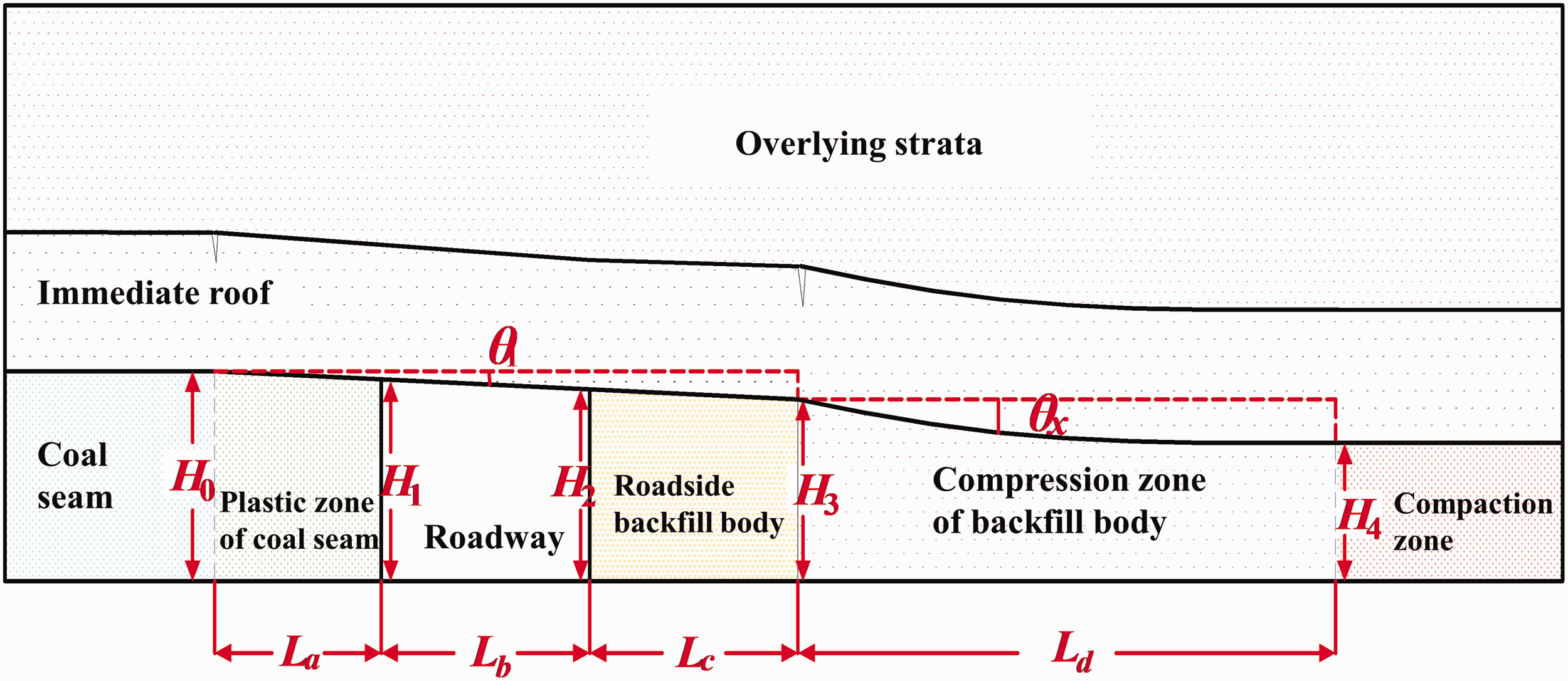
Model diagram of segmented roof movement.
The subsidence angle θ1 formed by the immediate roof at the roadside backfill body can be directly solved

According to the relevant regulations of coal mine safety, the reserved roadway section should meet a certain area Sh

The subsidence angle θx formed by the immediate roof in the compression zone can be solved by the following process. The goaf backfill body is assumed to be the elastic foundation, according to the theory of elastic foundation (Li et al., 2014), the deflection equation of roof subsidence in this stage is as follows
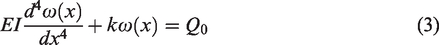
Substituting

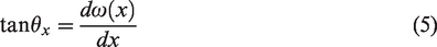
The derivative of the deflection equation is the slope of any point on the deflection curve, which is expressed by the dip angle as follows
The maximum value of roof subsidence deflection should not be greater than the sum of the maximum compression amount of backfill body and defective distance of roof-contact, namely

The strain ε of backfill material can be obtained by the confined compression test, then the stress-strain relationship of backfill material in laboratory compression test can be expressed as follows

Force analysis
The immediate roof segmented subsidence structure will inevitably exert pressure on the roadside backfill body during the formation process, so it is necessary to study the force law of the roadside backfill body under this condition. The mechanical model of the roadside backfill body is shown in Figure 4.
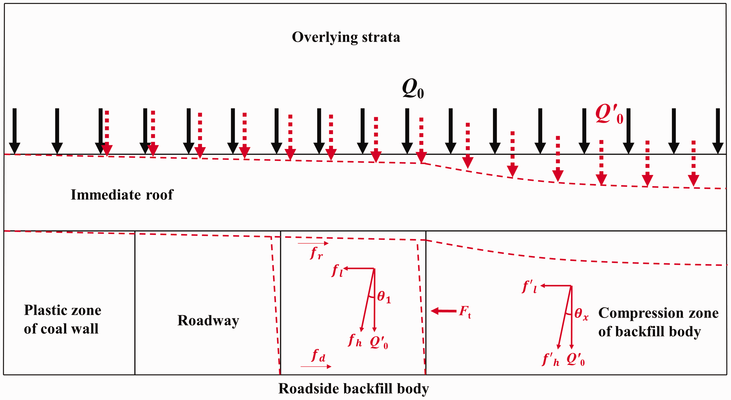
Mechanical model of roadside backfill body.
The inclined plane with a certain angle is formed in the process of roof segmental subsidence, and the load of overlying strata is assumed to be constant during the deformation of the immediate roof, Q0=Q′0. As shown in Figure 4, under the action of overburden load, the inclined resultant force (

It can be obtained by solving equation (9)

Where η is the stress concentration coefficient of the roadside backfill body; N is a constant, which is N = A + C.
The subsided roof compresses the backfill body, and the lateral pressure Ft is produced on the roadside backfill body. If the solid backfill material in goaf is regarded as noncohesive coarse fine mixed loose particle accumulation, according to the Coulomb static earth pressure calculation method, Ft can be expressed as

The condition for no lateral slippage of the roadside backfill body is that the friction between the roadside backfill body and the roof and floor (respectively


In addition, in order to maintain the integrity and stability of the roadside backfill body, its own strength Qp can not only support the vertical pressure of the overlying strata subsidence, namely:
From the above analysis, it can be seen that the formation and appearance characteristics of segmented subsidence structure with the immediate roof are closely related to the mechanical properties of the roadside backfill body and the goaf backfill body. The roadside backfill body is mainly subjected to vertical and lateral stress, and the force on the roadside backfill body is closely related to the subsidence angle of the roof, which is affected by goaf backfilled rate, roadside backfill body parameters and other factors.
Numerical simulation
In order to verify the characteristics of the segmented structure formed by the immediate roof subsidence under the conditions of different width and strength of roadside backfill body and different backfilled rates of goaf, and study the stress law of the roadside backfill body under this surrounding rock structure condition, based on the geological conditions of a backfilling mine in China, FLAC3D software is used for numerical simulation and analysis.
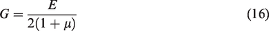
In the modeling process, it is necessary to determine the relevant mechanical parameters of the rock formation. The main parameters involved are bulk modulus, shear modulus, cohesion, internal friction angle and rock density. However, the bulk modulus and shear modulus of rock formations cannot be directly obtained by laboratory tests, they need to be solved indirectly with the aid of the elastic modulus and Poisson’s ratio of rock. The relationships among volume modulus, shear modulus, elastic modulus and Poisson’s ratio of rock are as follows (Xue et al., 2018)
Modeling
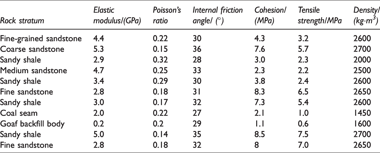
According to the geological conditions of a backfilling mine in China, the average depth of coal seams in the mine is 400 m, the average thickness of coal seams is 3 m, near horizontal seams, and the geological structure is simple. By consulting the mine’s geological data and rock formation sampling test, determine the rock formation histogram of the working face and the mechanical parameters of the rock stratum. The mechanical parameters of coal and rock are shown in Table 1.
Mechanical parameters of coal and rock formations.
The constitutive model used in the numerical model is the Mohr-Coulomb model with a size of 120 m × 140 m × 70 m (X × Y × Z). The X, Y and Z directions set different grid numbers according to the simulation scheme. In the model, roadways with a width of 3 m are reserved on the left and right sides of the backfilling area, 20 m coal pillars are reserved in front and back of the backfilling area, and 15 m coal pillars are reserved on the left and right, the excavation and backfilling distance is 100 m, FISH language is used to simulate excavation and backfilling process. The horizontal degrees of freedom are constrained around the model, while the bottom of the model is fixed, ignoring the effects of structural stress and boundary effects. According to the actual depth of the coal seam, the upper part of the model simulates the weight of the rock formation from the upper part of the model to the surface by applying an equivalent uniform load of 8.6 MPa. The numerical model is shown in Figure 5.
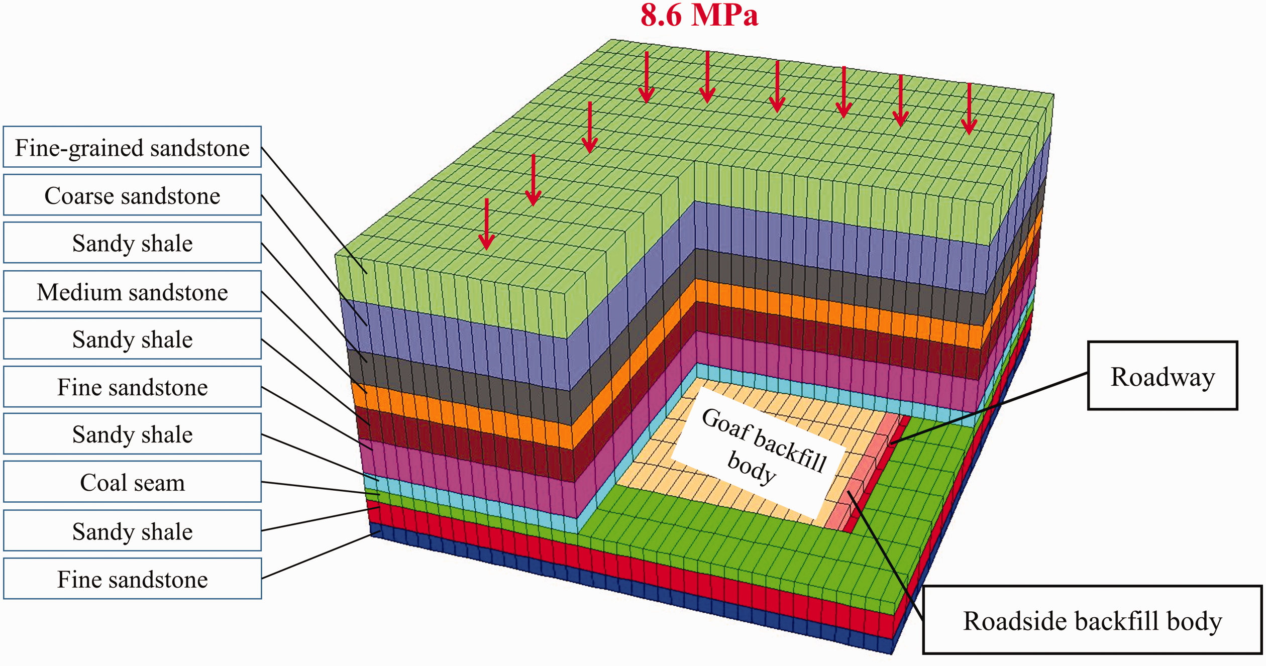
Model diagram of segmented roof movement.
Simulation scheme
In order to study the characteristics of the segmented structure formed by immediate roof subsidence under the conditions of different width and strength of roadside backfill body and different backfilled rates of goaf (Guo et al., 1992), the simulation scheme is shown in Table 2.
Model simulation scheme.
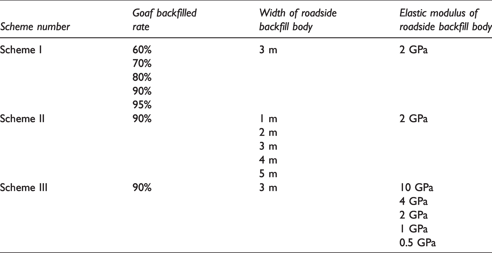
It should be noted that during the execution of the above simulation schemes, the roadside backfill body is always densely connected to the roof and floor. In the same scheme, only the corresponding variables are changed, and the other conditions remain the same. The elastic modulus of roadside backfill body in the numerical model represents the strength of roadside backfill body (Yu, 2013), that is, the higher the elastic modulus is, the higher the strength of roadside backfill body is. Therefore, the elastic modulus values of the roadside backfill body from large to small in Scheme III respectively represent the strength of the roadside backfill body from high to low.
Result analysis
Different goaf backfilled rates
In order to clearly show the segmented structure formed by the immediate roof subsidence under different goaf backfilled rates, the vertical displacement nephogram of the left roadway surrounding rock in the middle of the model (y = 70) is shown in Figure 6.
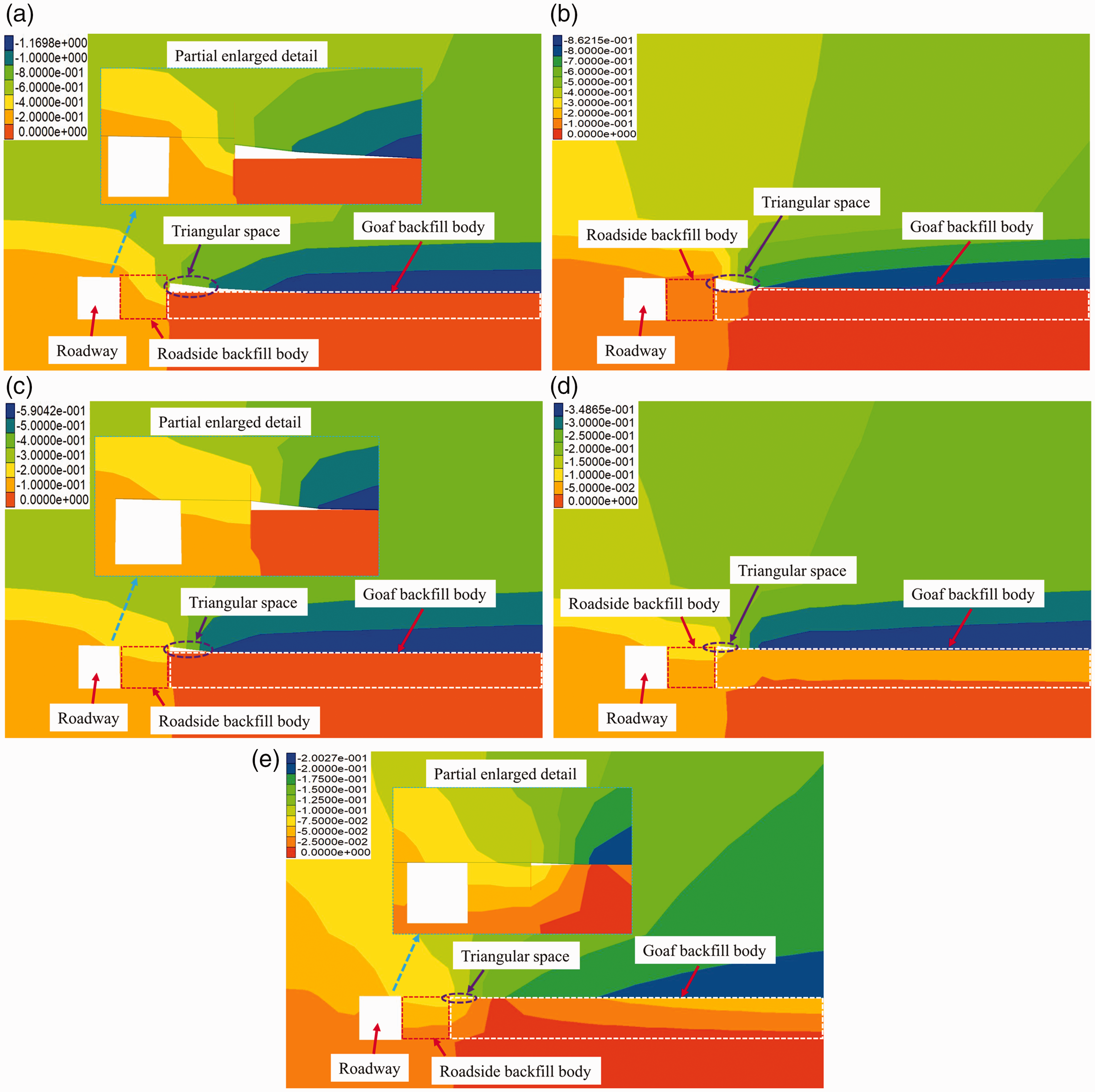
Vertical displacement nephogram of the model in Scheme I. (a) The backfilled rate of the goaf is 60%; (b) the backfilled rate of the goaf is 70%; (c) the backfilled rate of the goaf is 80%; (d) the backfilled rate of the goaf is 90%; (
It can be seen from Figure 6 that under different backfilled rates of goaf, the immediate roof forms a kind of segmented subsidence structure, and the appearance degree of this structure is closely related to the goaf backfilled rate, that is, with the decrease of goaf backfilled rate, the segmented structure formed by the immediate roof subsidence becomes more obvious. When the backfilled rate of goaf decreases from 95% to 70%, as shown in Figure 6(b)–(e), the deformation of the roof above the goaf will gradually increase with the roadside backfill body as the starting point, the gap between the immediate roof and the goaf backfill body will gradually decrease, and the roof will be close to the backfill body and contact. After contact, the roof will compress the backfill body until the overburden load and the resistance of the backfill body reach balance. If the balanced roof does not break and remains continuous in morphology, the triangular space will be formed between the roadside backfill body and the goaf backfill body. The size of the triangular space is negatively related to the backfilled rate of the goaf. When the backfilled rate of the goaf is 60%, the roof on both sides of the roadside backfill body will be dislocated, as shown in Figure 6(a), which shows that the backfilled rate of the goaf is low, the roof above the goaf is broken during the subsidence process, while the roof above the roadside backfill body only inclines and subsides.
Several points on the roof of the left roadway are selected and numbered from left to right. The point location and number are shown in Figure 7.
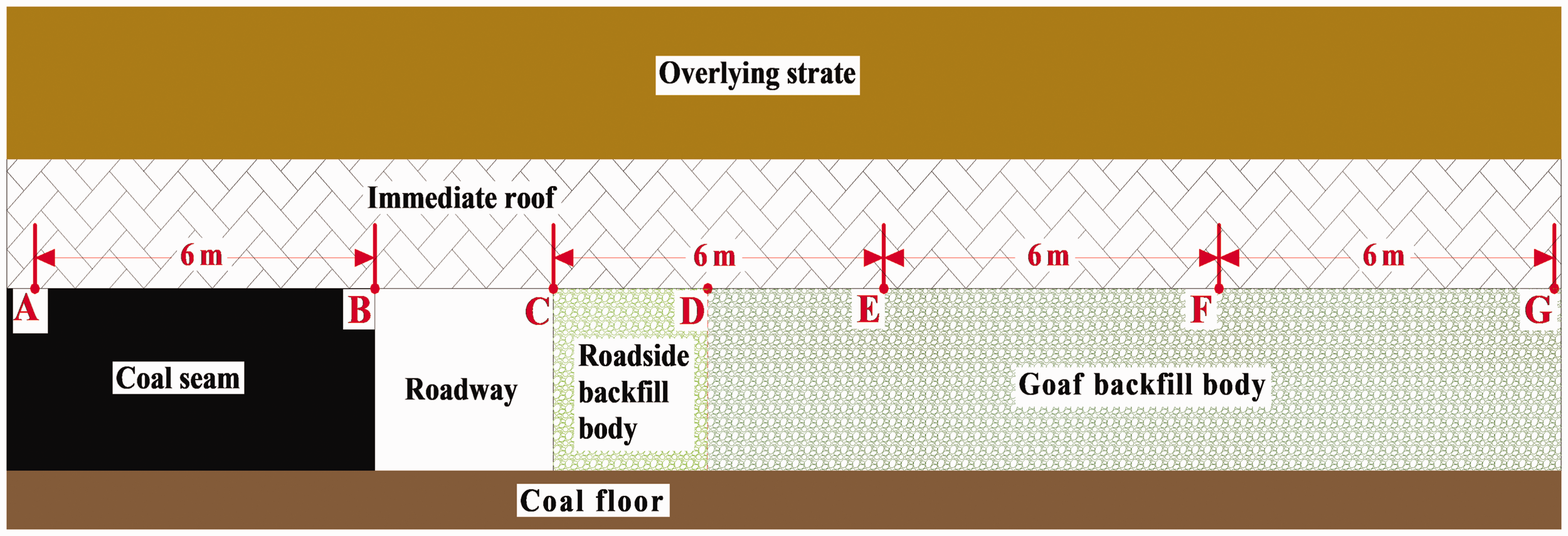
Schematic diagram of the roof measuring point arrangement.
The displacement value of each measuring point is shown in Figure 8. Moreover, the data such as the vertical stress on the coal wall and the roadside body is shown in Figure 9.
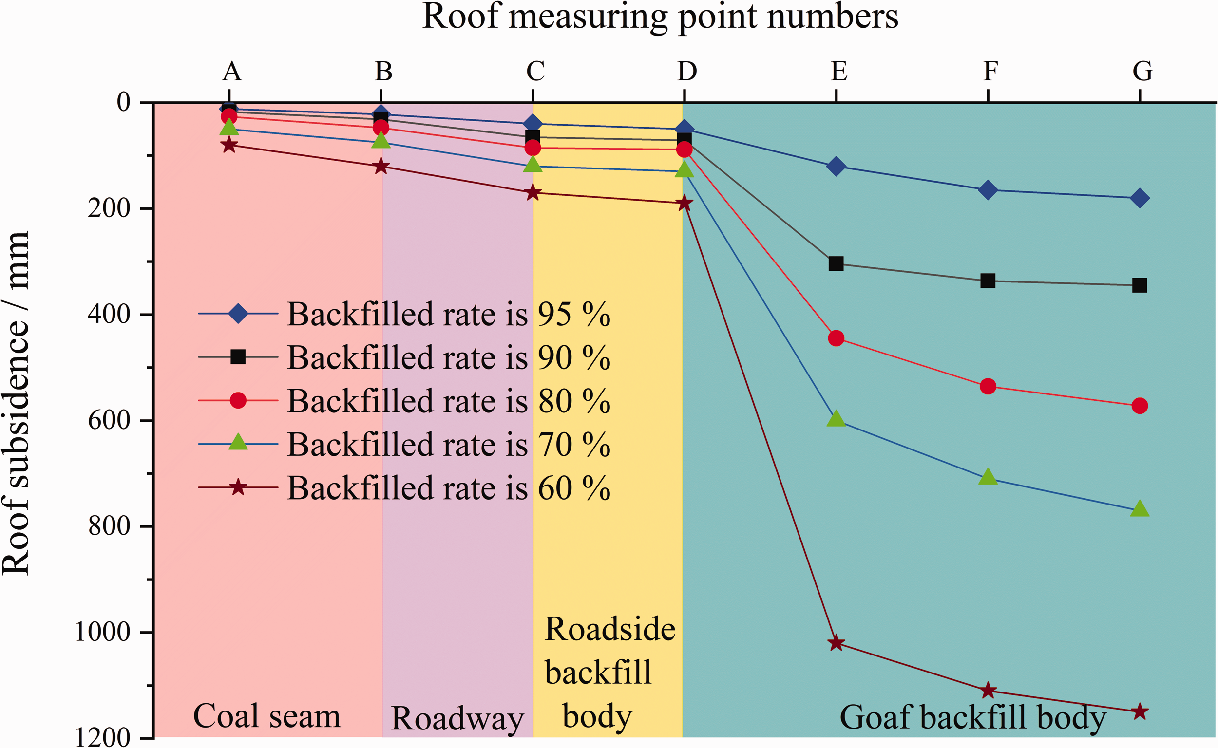
The subsidence amount of each roof measuring point in Scheme I.
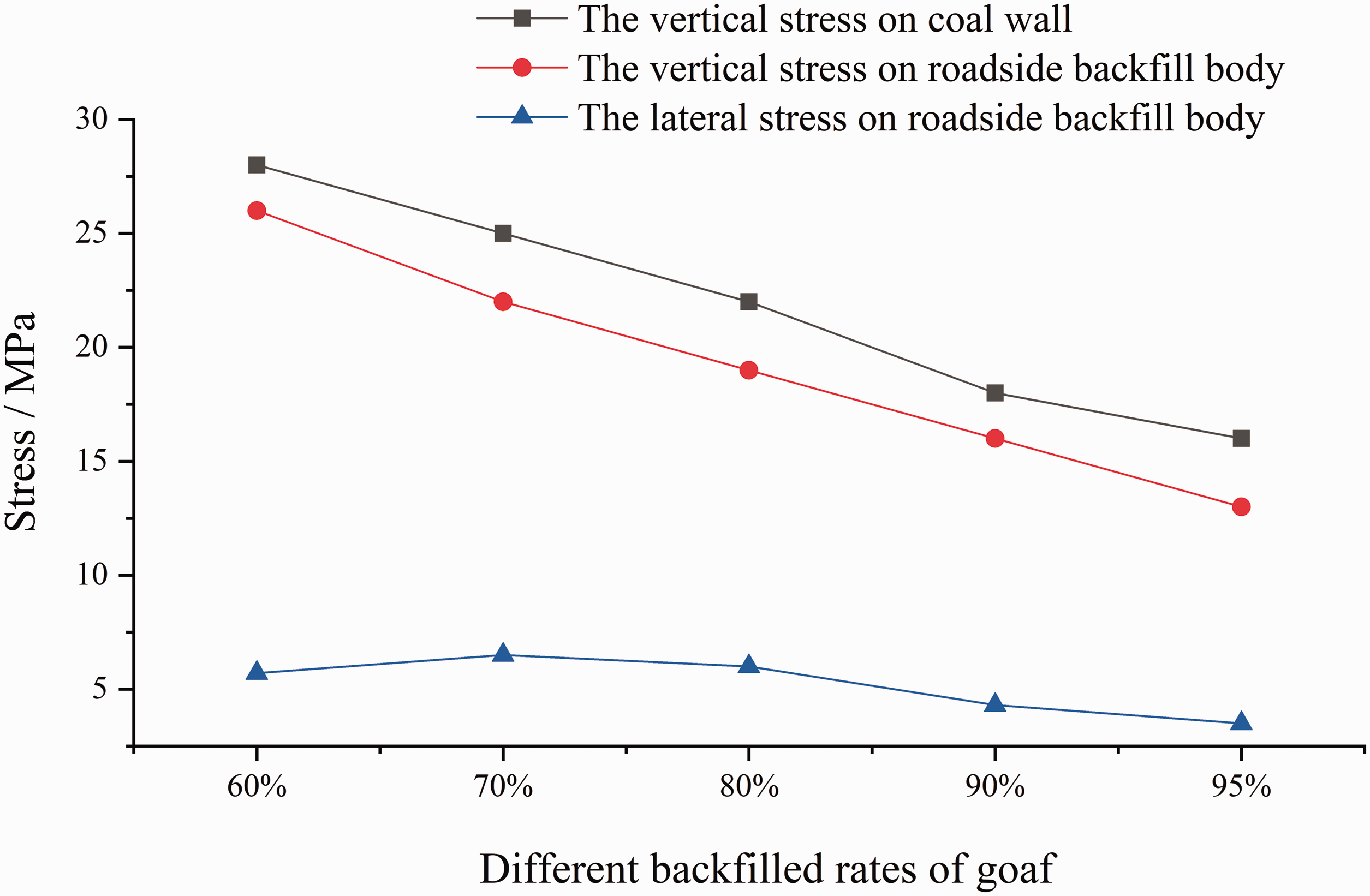
Stress on two sides of the roadway in Scheme I.
It can be seen from Figure 8 that from point A to point G, the subsidence amount of immediate roof increases in varying degrees. Taking point D as the turning point, the roof subsidence amount from point A to point D increases slowly, and the maximum subsidence difference between the two points is not more than 150 mm. From point D to point G, the roof subsidence amount increases sharply, and then the increasing trend slows down rapidly. According to the location of each point, taking the roadside backfill body as a turning point, the roof subsidence between the coal wall and the roadside backfill body is small. While the direction from the roadway to the goaf backfill body, the immediate roof first subsides violently, and then gradually becomes stable, and the lower the backfilled rate of goaf, the greater the roof subsidence at the same position. It can be seen that from the coal wall to goaf, due to the supporting effect of the roadside backfill body, the immediate roof on both sides of the roadside backfill body has formed two types of subsidence morphology. That is to say, the immediate roof between the coal wall and the roadside backfill body only gently inclined subsidence, and the dip angle of the immediate roof is small. While the immediate roof subsidence between the roadside backfill body and the goaf is severe, the dip angle is large, and the smaller the backfilled rate of goaf, the greater the difference of roof subsidence between the two sides of the roadside backfill body. When the backfilled rate of the goaf is 60%, the difference of the roof subsidence on both sides of the roadside backfill body is more than 1000 mm, indicating that the roof in goaf has broken and fall, which conforms to the roof subsidence morphology shown in Figure 6(a). Therefore, the lower the backfilled rate of goaf is, the more obvious the segmented subsidence morphology formed by the roof is. If the backfilled rate is small, the immediate roof will be damaged and fall.
It can be seen from Figure 9 that as the backfilled rate of the goaf increase, the roof dip angle between the roadside backfill body and the goaf becomes small, the vertical stress on the coal wall and the roadside backfill body show a continuous decreasing trend, which indicates that the higher the backfilled rate of the goaf is, the stronger the supporting effect of the backfill body on the roof is. The goaf backfill body can share the roof load, thereby reducing the stress transfer to the coal wall and the roadside backfill body, forming a coordinated support structure of the coal wall-roadside backfill body-goaf backfill body. In this case, the immediate roof is easier to maintain the continuity of morphology and force. While the lateral force on the roadside backfill body shows the variation law of first increasing and then decreasing with the decrease in the backfilled rate of the goaf. The reason is that when the backfilled rate of goaf is high, the subsidence angle of the immediate roof is small, so the horizontal component force exerted on the roadside backfill body is small in the process of roof compressing backfill body. As the backfilled rate decreases, the dip angle formed by the immediate roof subsidence increases, and the lateral force on the roadside backfill body increases accordingly. When the backfilled rate is low to a certain extent, such as backfilled rate of 60%, due to the less backfill materials in goaf, the roof will deform greatly and break, resulting in a small lateral pressure exerted on the roadside backfill body during the compression process of the goaf backfill body.
Different width of roadside backfill body
The Scheme II is used to simulate the deformation of surrounding rock under the condition of different width of roadside backfill body, and the vertical displacement nephogram of the left roadway surrounding rock at the middle position of the model (y = 70) is shown in Figure 10.
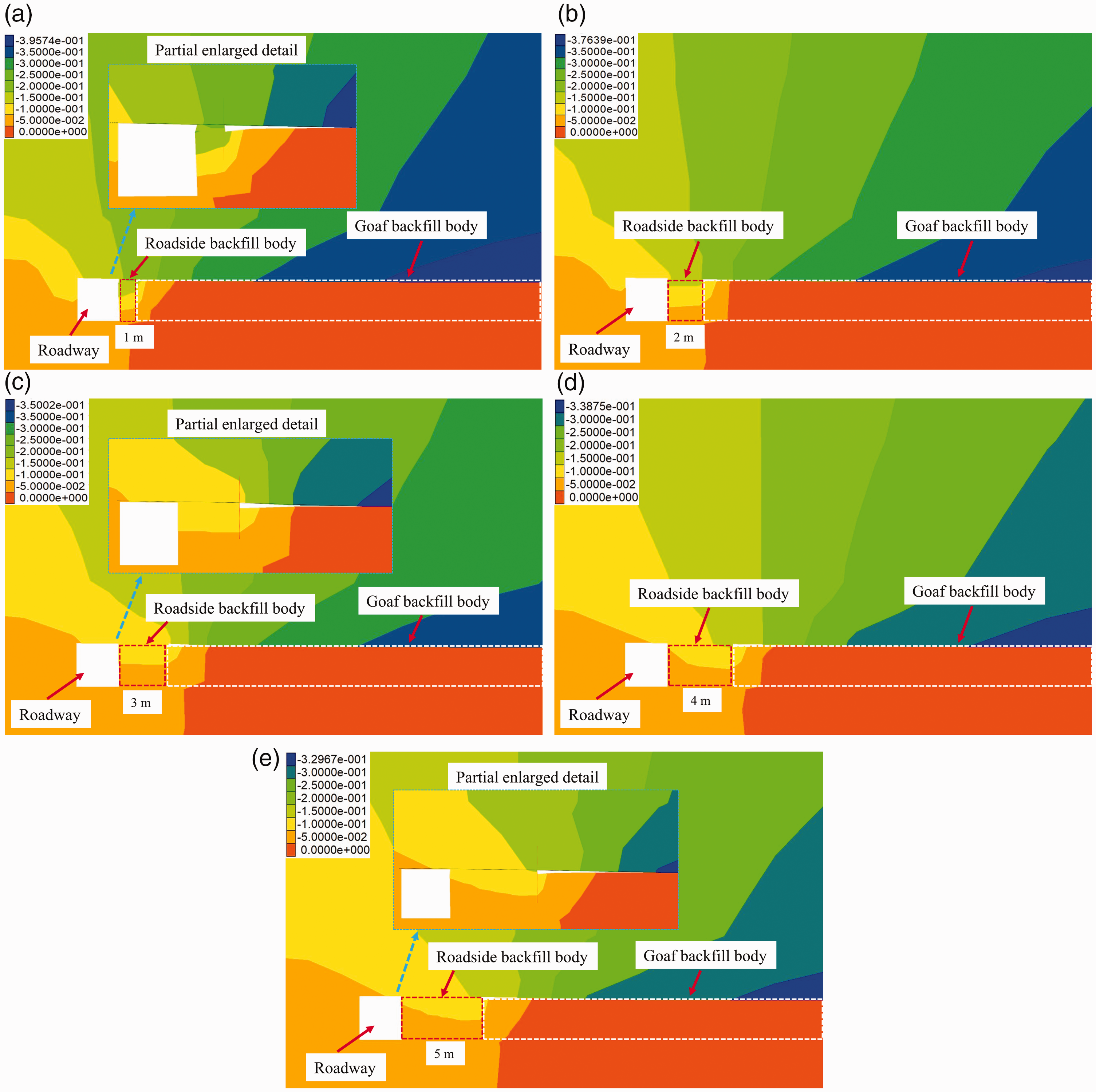
Vertical displacement nephogram of the model in Scheme II. (a) The width of roadside backfill body is 1 m; (b) the width of roadside backfill body is 2 m; (c) the width of roadside backfill body is 3 m; (d) the width of roadside backfill body is 4 m; and (e) the width of roadside backfill body is 5 m.
By comparing and analyzing the displacement nephogram of the model in Scheme II (as shown in Figure 10(a)–(e)), under the condition of 90% backfilled rate, no matter the width of roadside backfill body is 1 m, 3 m or 5 m, the subsidence degree of immediate roof in the position of roadside backfill body and goaf is obviously different, the roof subsidence is the largest in the depth of the goaf, while the roof subsidence is small in the position of roadside backfill body, the immediate roof presents a segmented subsidence structure, and the smaller the width of roadside backfill body is, the more obvious the segmented subsidence morphology of immediate roof is. As the width of the roadside backfill body increases, the roof control range increases accordingly, the immediate roof subsidence at the same position on both sides of the roadside backfill body decreases. The position of the same roof subsidence is gradually transferred to the depth of the goaf, which is beneficial to maintaining a certain range of immediate roof continuous morphology. It also shows that the larger the width of the roadside backfill body, the further the segmented structure formed by the immediate roof subsidence extends in goaf.
The stress data of the coal wall and roadside backfill body in the middle of the model (y = 70) are shown in Figure 11.
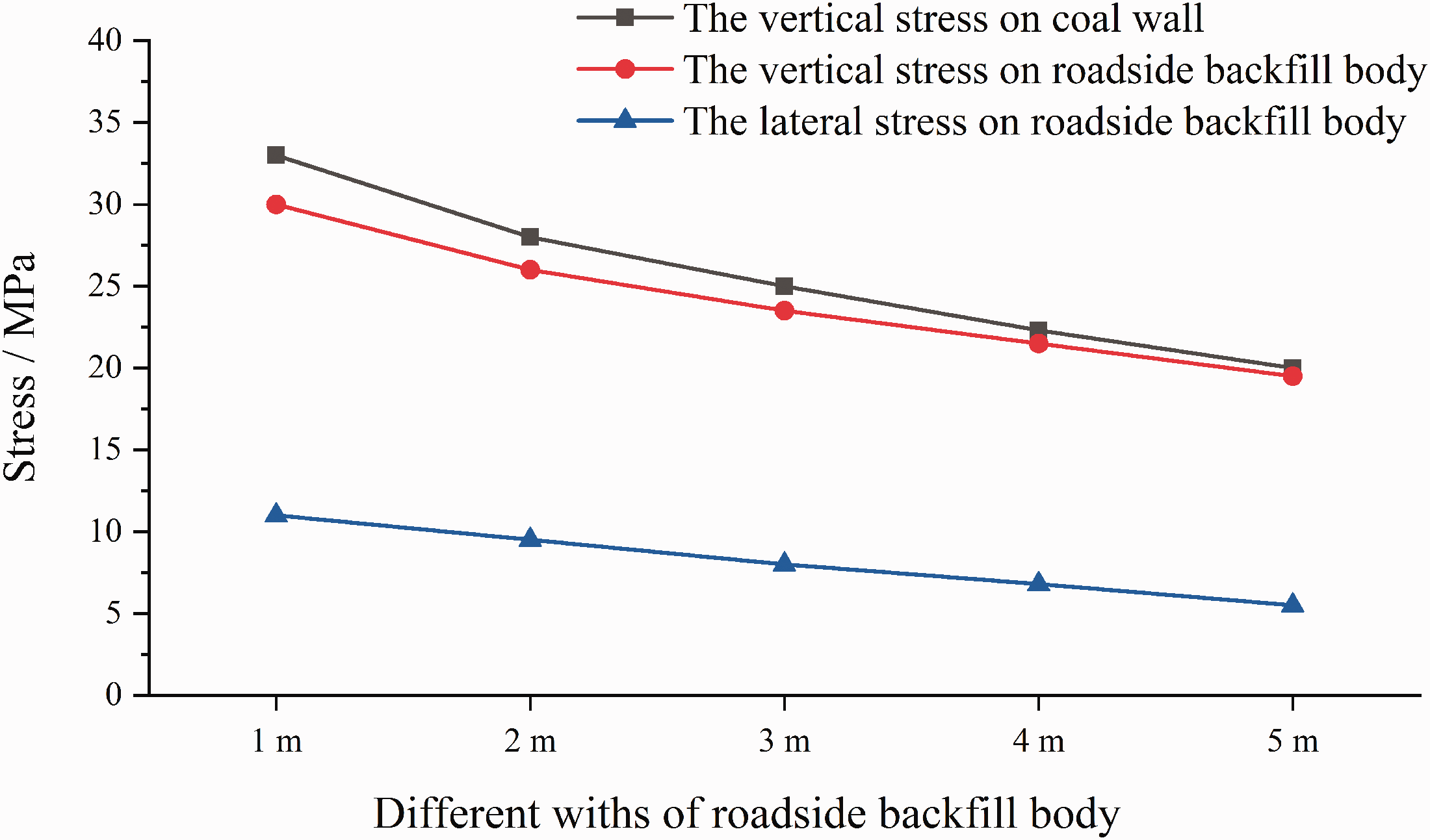
Stress on two sides of the roadway in Scheme II.
It can be seen from Figure 11, as the width of the roadside backfill body increases, the vertical stress on the coal wall, the vertical and lateral stress on the roadside backfill body all show different degrees of decreasing trends, indicating that the width of the roadside backfill body increases, the joint support of the roadside backfill body and the goaf backfill body on the roof is enhanced, thereby reducing the subsidence and inclination degree of the roof in goaf, the stress on the coal wall and the roadside backfill body are reduced, the integrity of the surrounding rock of the roadway is good. When the width of the roadside backfill body is from 1 m to 3 m and from 3 m to 5 m, the vertical stress on the roadside backfill body decreases by about 6 MPa and 3 MPa respectively, and the lateral stress decreases by about 4 MPa and 2 MPa respectively. It can be seen that when the width of roadside backfill body is from 1 m to 3 m, the force on roadside backfill body decreases greatly; over 3 m, the downward trend of the force on the roadside backfill body slows down, and as the width of the roadside backfill body increases, the vertical forces on the coal wall and the roadside backfill body gradually become consistent.
Different strength of roadside backfill body
According to the measuring point position in Figure 7, the data of roof subsidence and stress of roadside backfill body under different strength conditions are shown in Figures 12 and 13.
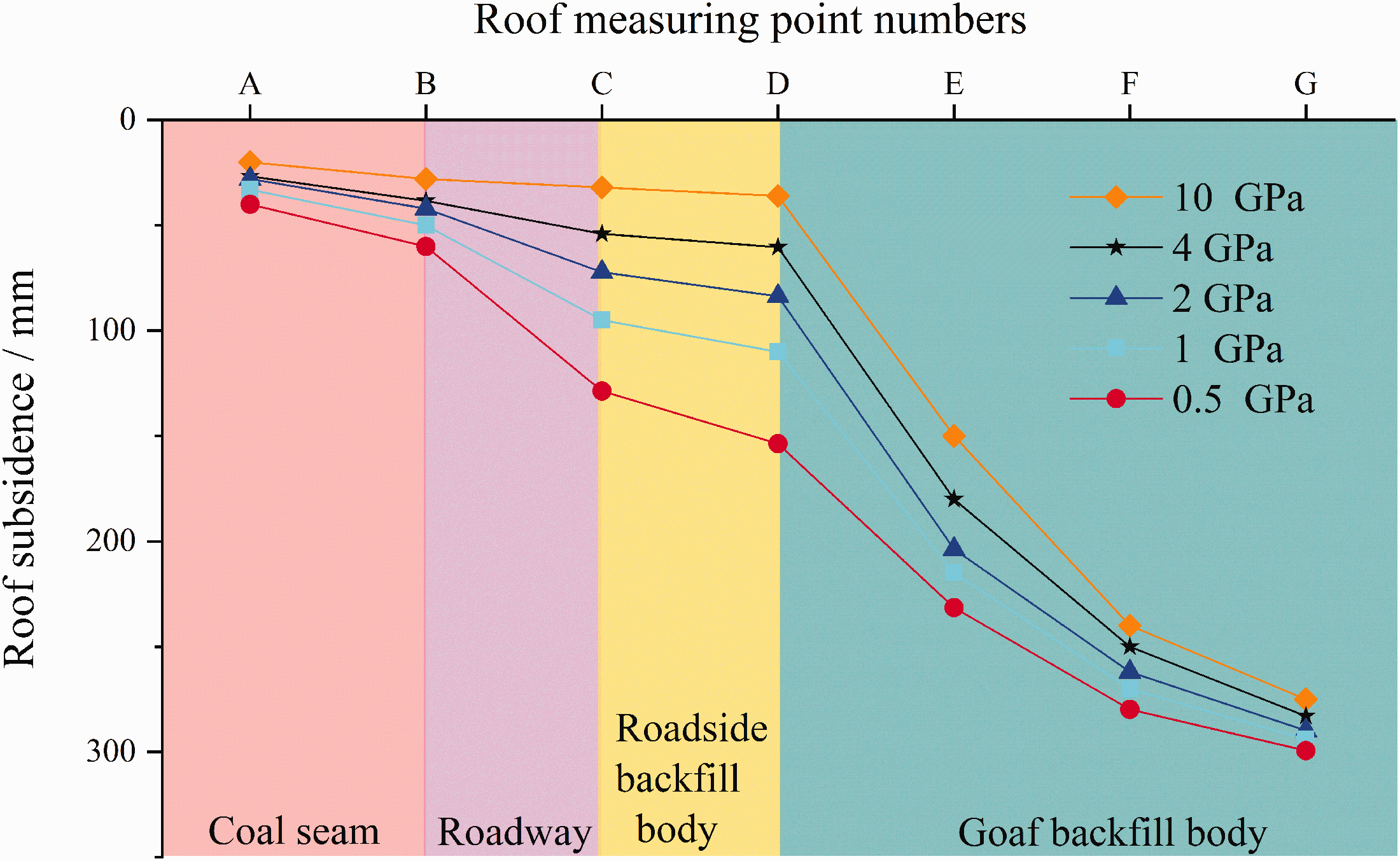
The subsidence amount of each roof measuring point in Scheme III.
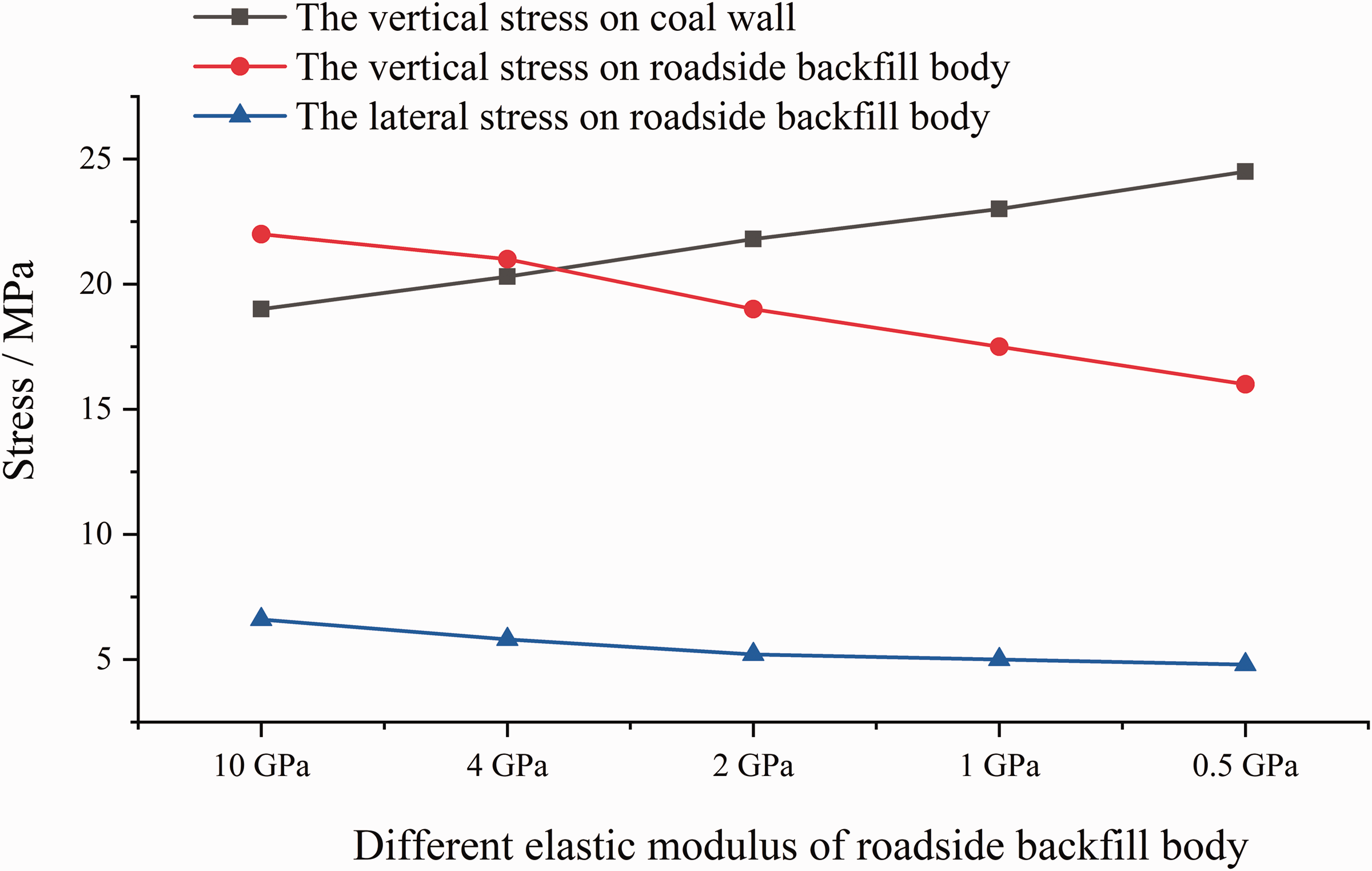
Stress on two sides of the roadway in Scheme III.
As can be seen from Figure 12 that under different conditions of different elastic modulus of roadside backfill body, the immediate roof has subsided to different degrees between point A and point D and between point D and point G, forming a segmented structure. As the decrease of the elastic modulus and strength of the roadside backfill body, the subsidence of the roof above the roadside backfill body increases, the difference between the roof subsidence above the roadside backfill body and that of the goaf decreases. It shows that in the case of low strength of the roadside backfill body, the roof from the coal wall to the roadside backfill body has a large amount of subsidence and the degree of inclination is severe. While along the roadside backfill body to the goaf direction, the roof is nearly synchronously subsidence, and its maximum subsidence eventually tends to be the same in the depth of the goaf, which is about 300 mm. In this case, the immediate roof in goaf has good continuity and small inclination degree, and the structural morphology of the immediate roof is easy to form the shape shown in Figure 2(a). The segmented structure formed by the immediate roof subsidence is transferred to the coal wall, which leads to the reduction of the roadway section and the serious damage of the surrounding rock. Moreover, the roof fracture is easy to occur near the coal wall, which seriously affects the maintenance of the roadway and has great potential safety risks.
It can be seen from Figure 13 that as the strength of the roadside backfill body decreases, the force on the coal wall increases, while the vertical and lateral stresses on the roadside backfill body show a decreasing trend. The reason is that the high-strength roadside backfill body has a small compression amount, can support the roof together with the coal wall, bear part of the concentrated stress transfer from the coal wall. Moreover, the immediate roof has a small amount of subsidence at the high-strength roadside backfill body, and a large amount of subsidence in goaf, the difference in the degree of roof subsidence between the two positions is large, resulting in a greater dip angle formed by the roof subsidence in goaf, and then exerting a larger horizontal component on the roadside backfill body, which causes the lateral force on the roadside backfill body to increase. Therefore, in the on-site roadway retaining project, the strength of the roadside backfill body should be moderate considering the factors such as the force on the roadside backfill body, roof subsidence amount and roadway retaining cost.
Analysis of engineering example
In order to study the roof subsidence structure of gob side entry retaining in backfill mining, a mine in Shandong Province of China is selected as an example for analysis (Miao et al., 2020). The mine level is -810 m, the length of a working face is 85 m, and the average mining height is 2.7 m. The immediate roof is siltstone, the main roof is 4 m thick fine-grained sandstone, and the immediate floor is mudstone. The mining roadway has a width of 5 m and a height of 3.7 m, which is excavated along the roof and floor of the coal seam and is combined supported by rockbolts, meshes and cables. The gangue wall is used as the roadside backfill body in the gangue transport roadway of the working face, and the gangue is used for the conventional backfilling operation in goaf. In the process of gob side entry retaining, two different backfilled rates of 60% and 80% were used in the two stages of roadway retaining respectively, and the deformation monitoring of roadway surrounding rock was carried out for 60 days. The monitoring results are shown in Figure 14.
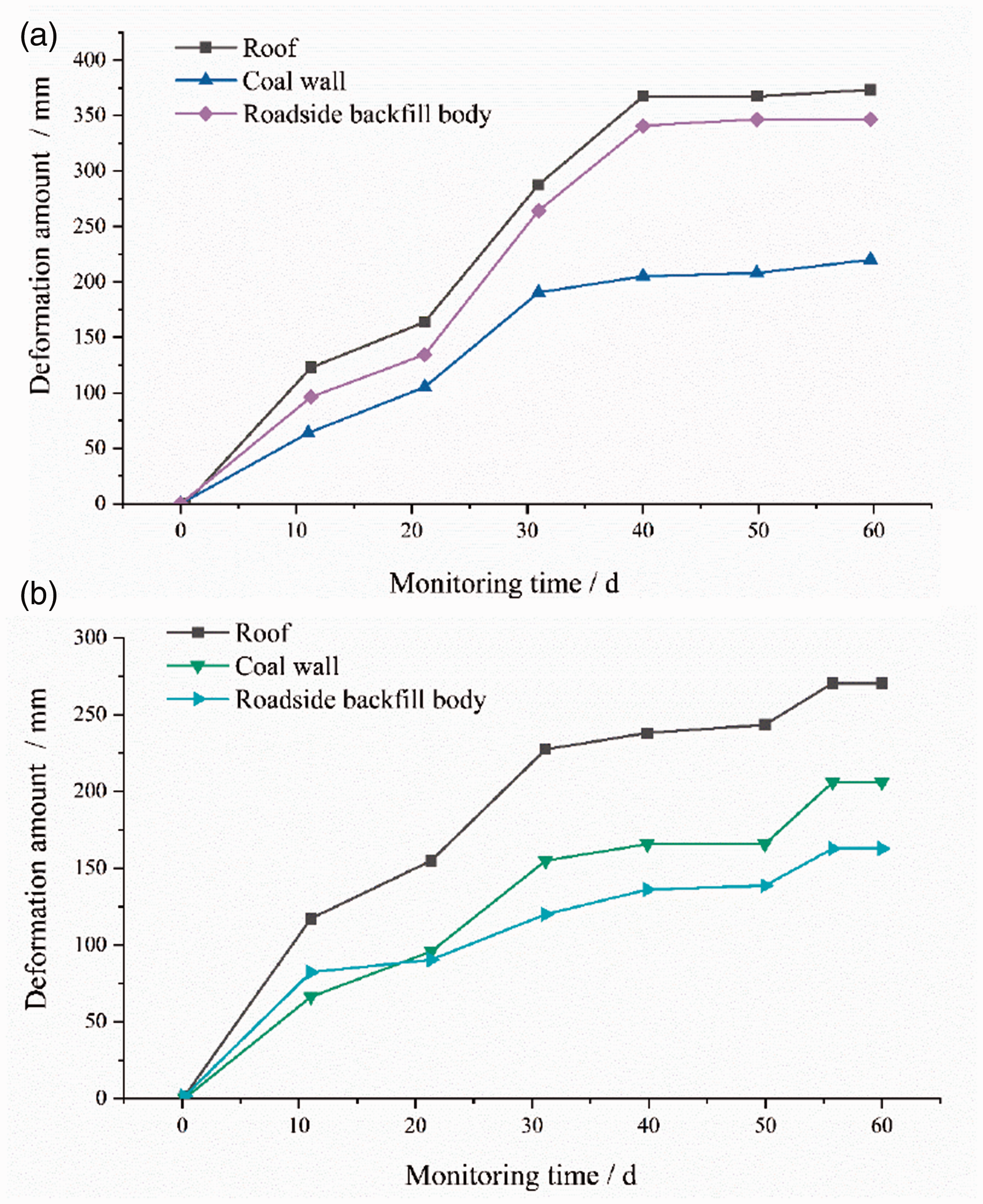
Deformation of roadway surrounding rock under different backfilled rates conditions. (a) The backfilled rate of goaf is 60% and (b) the backfilled rate of goaf is 80%.
As shown in Figure 14, during the advancing process of the working face, the deformation of the surrounding rock increases first and then stabilizes with the increase of monitoring time. Through the comparison of the roof subsidence amount, deformation amount of roadside backfill body and coal bank under the two backfilled rates, it is found that when the goaf backfilled rate is low, the deformation of roadway surrounding rock increases, which reflects the increase of force on roof and roadside backfill body. The above phenomenon shows that the backfilled rate of the goaf is reduced, and the degree of roof subsidence on both sides of the roadside backfill body is different greatly, which is not conducive to the safety and stability of the roadside backfill body. Therefore, the improvement of goaf backfilled rate not only effectively supports the bending subsidence of goaf roof, weaken the appearance degree of roof segmented subsidence structure, but also has an obvious control effect on the deformation degree of roadway surrounding rock.
Conclusions
This paper analyzes the interaction between the roof and backfill body under the background of roadway retaining along the backfilling area, constructs two models of immediate roof subsidence under two extreme conditions, and puts forward a kind of segmented subsidence structure with the immediate roof of gob side entry retaining in backfill mining. The segmented subsidence structure model of the immediate roof is established, and the mechanical analysis of the roadside backfill body is carried out. The results show that the structural characteristics of immediate roof segmented subsidence are mainly closely related to goaf backfilled rate, width and strength of roadside backfill body. The numerical simulation results show that the backfilled rate of goaf decreases, the segmented structure formed by roof subsidence is more obvious, the vertical force on the coal wall and the roadside backfill body is higher. The width of the roadside backfill body increases, the force on the roadside backfill body decreases, and the segmented subsidence structure of the roof extends to the depth of goaf. The strength of the roadside backfill body decreases, the roadway roof subsidence amount increases, and gradually synchronizes with the roof subsidence in goaf, resulting in the formation position of the immediate roof segmented structure transfers to the coal wall, which destroys the safety and stability of the roadway. Based on the engineering practice of a mine in Shandong Province of China, the deformation of roadway surrounding rock under different backfilled rates is monitored and analyzed. The results show that increasing the backfilled rate of goaf can weaken the appearance degree of roof segmented subsidence and effectively control the deformation of roadway surrounding rock.
Footnotes
Acknowledgements
We are very grateful to the reviewers and editors for their valuable comments and suggestions.
Declaration of conflicting interests
The author(s) declared no potential conflicts of interest with respect to the research, authorship, and/or publication of this article.
Funding
The author(s) disclosed receipt of the following financial support for the research, authorship, and/or publication of this article: This research was funded by the Key Consulting Project of Chinese Academy of Engineering (2020-XZ-13), China National Key Research and Development Program (2019YFC1904304) and Key R&D Program Projects in Hebei Province (18273815 D).