
Abstract
Based on the principle of energy-accumulated directional blasting technology, the penetration condition of damage between blasting holes is established. The laws of blasting stress evolution, the development of directional cracks, and the directional blasting parameters are examined by the methods of theoretical analysis, numerical simulation, and field testing. Based on the results of the Finite Element (FE) numerical simulation, a tensile stress of 91.2 MPa is generated on the blasting hole wall in the designated direction, which can fracture the rock mass to form directional cracks. With the action of the detonation stress, the length and width of directional damage in the rock mass increase continuously. The combined roof structure of “lower short-arm beam and upper masonry beam” is created after mining by the use of directional blasting to presplit the roof. The combined roof structure is more conducive for the stability of the retained entry. Taking the 21304 working face of Chengjiao coal mine as the engineering background, the directional blasting parameters are determined by doing theoretical analysis and conducting field tests, such as the blasting hole depth of 8 m, the blasting hole angle of 15°, the spacing between blasting holes of 500 mm, the single-hole charge structure of “4 + 3 + 2 + 0,” with the sealing length set at 2 m. When the determined blasting parameters were used to retain the entry, the roof in the goaf collapsed along the structural surface formed by directional blasting and the gangues filled the entire roadway quickly. Further, the surrounding rock of the retained entry was stable at about 290 m behind the working face, and a good retaining effect was obtained at the entry. The research results are significant for improving the technical system of gob-side entry retaining by roof cutting (GERRC), and provide guidance for the application of GERRC.
Keywords
Introduction
Coal is one of the main energy sources in China. The coal pillar mining method not only causes a lot of waste of resources (Islavath et al., 2016), but also easily leads to coal mine power disasters (Holub et al., 2011; Konicek et al., 2013; Krause, 2015; Rezaei et al., 2015). The use of nonpillar mining methods represents a crucial pathway for achieving sustainable coal extraction and scientific advancement in the mining sector of China (Alehossein and Poulsen, 2010; Liu et al., 2018). A progressive method within nonpillar mining is known as gob-side entry retaining by roof cutting (GERRC), which involves the use of directional explosives to sever the mechanical link between the roadway roof and the gob strata. Following the extraction process, the goaf strata naturally collapse, resulting in the formation of a waste rock mound that provides support to the roof above, thereby fulfilling the objective of eliminating the need for roadside backfill. Currently, GERRC technology has been effectively implemented in various mining operations characterized by distinct geological settings (Hu et al., 2023; Liu et al., 2021; Yang et al., 2020), significant economic and social advantages have been achieved. However, most of the studies on GERRC focus on control technology, surrounding rock structure (Xu et al., 2024) and stability mechanism (Yang et al., 2023), with less research on directional blasting for GERRC.
A critical aspect of GERRC involves the presplitting of the roof, which significantly influences the ultimate quality of the preserved entry. In the context of GERRC, the application of directional blasting techniques serves to initiate the presplitting of the roof while simultaneously safeguarding the stability of the roof rock layers. Directional blasting technology is widely used in the industries of construction, water conservancy, transportation and mining. It is mainly used for presplitting the roof to relieve the pressure and enhancing coal seam permeability in the mining field (Chen et al., 2019; Yang et al., 2017). There has been extensive research conducted on these topics, resulting in a wealth of important findings. An investigation was conducted concerning the mechanical properties of coal and the processes involved in crack development resulting from shaped charge detonations by Guo et al. (2012). Liu et al. (2014) conducted a simulation experiment to explore the characteristics of cracks and the evolution of stress associated with deep hole energy-accumulated directional blasting. Chen et al. (2015) conducted a study, the dynamics of a pilot hole used for rock slicing and pressure alleviation in robust thick roofs were examined, along with an investigation into how various factors affect the outcome of blasting operations. A new finite-discrete elements method was used to study the directional blasting of rock by Li et al. (2023). Wu et al. (2024) studied the influence of different materials of energy gathering tubes on directional blasting. The studies for directional blasting mainly used numerical simulations and physically similar experiments, but there were still some issues about it, such as the unsatisfactory effect of directional cracks in numerical simulations. Rocks are in open space in physical simulation experiments, while rocks are under confining pressure in actual engineering, resulting in inconsistent stress environments. Moreover, the similarity experiment of directional blasting did not consider the various rock types of the roof, which will affect the placement of explosives. Therefore, further studies are needed on directional blasting.
After conducting the review over previous literatures, it is found that the research on energy-accumulated directional blasting mainly focuses on the aspects of roof rock presplitting and coal seam permeability enhancement in the mining field. Considering the aspect of energy-accumulated directional blasting in GERRC, the available research work and technical theory at present are insufficient. Thus, in this paper, the laws of stress accumulation-diffusion and directional crack development of energy-accumulated directional blasting is studied. Additionally, the investigation into the functioning of GERRC as well as the characteristics of energy-accumulated directional blasting is conducted through theoretical examination, finite element numerical simulations, and practical field testing. The findings derived from this study hold considerable importance for advancing the theoretical framework and technical aspects associated with the GERRC.
Analysis of crack formation mechanism
Energy-accumulated blasting technology and its crack formation mechanism
The directional blasting is achieved by the energy accumulation effect of energy collecting tube on the explosives. As shown in Figure 1, energy collecting tube are mainly composed of the tube body and two rows of 180° symmetrically distributed energy collecting holes.
Structure of energy collecting tube.
While performing directional blasting, the energy collecting tubes with mining explosives are placed in the blasting holes prior to blasting. The direction of the energy collecting tubes in each blasting hole is adjusted so that all energy collecting holes form a straight line along the roadway direction. Following the detonation of the explosive, the presence of the energy collecting apertures leads to a concentration of tensile stress being generated in a vertical alignment to these apertures, thereby causing the surrounding rock mass to fracture in accordance with the predetermined alignment of the energy collecting holes. Given that the area around the energy collecting holes on the tube serves as the pivotal zone, the explosive is capable of creating a “pressure air wedge” extending in the direction of these holes. This will lead to a progressive widening of the fracture in the designated direction, ultimately resulting in a fissure that extends along the entire length. Additionally, the tubular structure provides a safeguard, resulting in significantly less disruption to the rock mass in directions not intended. The principle of energy-accumulated directional blasting is shown in Figure 2. Consequently, the technology of energy-accumulated directional blasting facilitates the targeted fracturing of rock formations and effectively severs the roof of the roadway.
Principle of directional blasting by energy accumulation.
Theoretical analysis
According to the previous study (Wang et al., 2019), the impacted area of energy-accumulated directional blasting can be divided into three zones, viz., crushing zone, tension crack zone and crack propagation zone. The detonation gas wave collides with the hole wall, creating an explosive shock wave that propagates through the rock. Since the impact pressure of the shock wave is significantly larger than the dynamic compressive strength of the rock, the rock is crushed and a crushing zone forms. The explosion shock wave gradually weakens during propagation and becomes the explosion stress wave at the crushing zone's periphery. At this point, the stress wave resulting from the explosion is insufficient to inflict compressive damage on the rock. Nevertheless, the presence of the energy collection tube induces tangential tensile forces within the rock. Once this tensile stress surpasses the dynamic tensile limits of the rock, it results in the formation of radial tensile fractures, creating a zone of tension cracks. Consequently, the radial fractures become subject to the compression of explosive gases driven by the gas wedge effect, thereby intensifying the tensile stress at the cracks’ leading edge. These waves of stress contribute to the continuation and widening of the fractures, thereby creating a zone of the cracks propagation.
According to the C-J model of condensed explosives, the pressure of the detonation wave can be expressed as follows (Gamezo and Oran, 1997):
Considering the influence of an energy collecting effect and the uncoupled charge structure on the detonation stress field, the peak pressure on the hole wall during energy-accumulated directional blasting can be expressed as:
The radial peak stress of the explosion stress wave in the rock is:


Tangential peak stress σθ can be expressed as:

During blasting, the rock is in a three-directional stress state, and the stress intensity on a point in the rock, namely, Mises effective stress, is:

In the case of tension and fracture of the rock in the tension crack zone, the following condition shall be fulfilled. i.e.,

The calculation formula for the radius of the rock blasting damage is :

Fe numerical simulation
Fe modeling details
The dynamic analysis software LS-DYNA is used to establish a finite element numerical model of single hole energy-accumulated blasting (Cho et al., 2008; Marko et al., 2017; Yilmaz and Unlu, 2013), with dimensions of 1000 × 1000 × 52 mm. The diameter of the borehole is 48 mm, the diameter of the explosive charge measures 27 mm, the radial decoupling ratio measures 1.78. The energy collection tube has an outer aspect of 42 mm, with an inner diameter measuring 39 mm. The energy collecting tube features a total of five perforations for energy collection. and each of the energy collecting apertures measures 4 mm by 4 mm, with a distance of 4 mm separating them. The finite element numerical model is illustrated in Figure 3.
Numerical model of energy-accumulated blasting.
The energy-accumulated blasting model is formulated using ALE and multi-material fluid-solid interaction techniques in the FE numerical simulation framework. The Jones–Wilkins–Lee (JWL) state equation explains the association between the pressure and volume of products resulting from an explosive detonation. As follows, the JWL state equation is articulated in a general form (Yang et al., 1996):

Parameters of the explosives and JWL state equation are listed in Table 1.
Parameters of the explosive and JWL equation.
The air is modeled with a density of 1.25 kg.m−3. The plastic motion model is adopted for the energy collecting tube, and its basic parameters are shown in Table 2.
Model parameters of the energy collecting tube.
The Riedel–Hiermaier–Thoma (RHT) model represents the mechanical behavior of rock, with its stress-strain relationship delineated into three distinct phases: the elastic phase, followed by linear strengthening, and culminating in damage-induced softening. This framework effectively represents extensive deformation of rock materials subjected to high levels of stress. The emergence of plastic strain, regardless of whether it occurs during the elastic phase or the linear strengthening period, does not result in any cumulative damage. Damage accumulation begins only when the strength of the equivalent stress surpasses the threshold of failure stress, transitioning the material into a phase of damage softening.
FE analysis results
Stress analysis
The changes in stress across all segments of the blasting hole along the Z axis exhibit a similar pattern. To facilitate the observation, the stress evolution of the section at Z = 0 is selected for analysis. The stress progression within the blasting hole is illustrated in Figure 4.
Stress evolution of energy-accumulated blasting.
It can be seen from Figure 4 that when t = 4.484 × 10⁻⁶ sec, the detonation products pass through energy collecting holes and directly act on the wall of the blasting hole. This forms a compressive stress field in the direction of the energy collecting holes, with the maximum compressive stress up to 95.5 MPa. Due to the effect of the energy collecting tubes, the tensile stress wave is initially generated on the walls of the blasting holes in the energy-accumulated direction at t = 7.996 × 10⁻⁶ sec. At this time, the tensile stress of the hole walls in the energy-accumulated direction is 5.3 MPa. When t = 10.477 × 10⁻⁶ sec, the effect of the energy collecting tubes becomes more obvious. The tensile stress range and the tensile strength of the rocks in the energy gathering direction increase sharply, and the maximum tensile stress value reaches 91.2 MPa, which is sufficient enough to expand and break the rocks with a formation of directional crack. With the explosion stress wave spreading outward, a “butterfly knot” shaped compressive stress is formed outside the tensile stress field. When t = 24.966 × 10⁻⁶ sec, the tensile stress waves caused by the energy accumulation gradually disappear, the “butterfly knot” compressive stress field continues to spread outward, and the stress intensity decreases sharply. At this time, the maximum compressive stress is only 2.4 MPa. When t = 38.992 × 10⁻⁶ sec, the blasting stress wave continues to transmit outwards. Due to the protective effect of the energy collecting tubes on the rocks in the nonenergy accumulated direction, an elliptical compressive stress field with long energy-accumulated direction and short non energy-accumulated direction is formed. When t = 61.925 × 10⁻⁶ sec, the stress waves become even weaker, and the impact of blasting on rock is virtually eliminated.
Deformation damage analysis
The section at Z = 0 is selected for deformation damage analysis, and the FE numerical simulation results of deformation damage evolution of the blasting holes are illustrated with the help of Figure 5.
Damage evolution of energy-accumulated blasting.
As shown in Figure 5, the effect of the energy-accumulated directional cracks is obvious. When t = 18.469 × 10⁻⁶ sec, the rock on the left side of the blast hole shattered in the energy-accumulated direction with a damage length of around 10 mm. The rock mass on the right side has also been damaged in the energy-accumulated direction, but the damage is not obvious. When t = 20.998 × 10⁻⁶ sec, the damage to the rock on the left side of the blast hole continues to develop in the energy-accumulated direction, and the damage to the rock on the right side has also penetrated the blast hole wall. From t = 20.998 × 10⁻⁶ sec to t = 54.992 × 10⁻⁶ sec, the damage length and width of the rock in the energy-accumulated direction continues to increase, and no obvious damage is finally produced in the rock in the nonenergy accumulated direction. This indicated the technical advantages of energy-accumulated blasting in directional fracture of the rock as well as in avoiding the damage of the rock in the nonset direction.
Mechanism of GERRC
Once the coal is extracted from the working face, the immediate roof detaches and subsequently collapses. Upon reaching the ultimate collapse distance for its overhang length, the basic roof will also break, rotate and sink. Finally, the basic roof of the gob-side entry retaining will form a masonry beam structure composed of rock blocks. The basic roof of the gob-side entry retaining is often damaged at the coal seam side, resulting in a long lateral cantilever at the goaf side. Due to be located directly below the long cantilever beam, the entry-side support bears a massive additional load, which may be detrimental to the stability of gob-side entry retaining.
The discrete element software 3DEC is used to simulate the roof collapse form and surrounding rock structure characteristics of gob-side entry retaining with different technologies. The simulation results are shown in Figure 6. As shown in Figure 6(a), when the roof is not cut off, the direct roof collapses smoothly with the advancing of the working face and the basic roof forms a large area of suspension at the side of the goaf. The weight of the long cantilever beam and the overlying rock layers is imposed on the entry-side filling body, causing it to bear a large additional stress and resulting in the serious deformation of the entry-side filling body and large roof subsidence of the gob-side entry retaining. As seen in Figure 6(b), when the technology of GERRC is adopted, the directional blasting cuts off the connection between the goaf roof and the roadway roof. After mining operation, the direct roof and basic roof will collapse smoothly along the roof fracture line. The lateral cantilever length of the basic roof will be greatly reduced, and the roof pressure will be fully alleviated. This will establish the retained entry in a low stress area environment and relieve the problem of stress concentration in the surrounding rocks of the retained entry. Therefore, the surrounding rock deformation of the retained entry can be greatly reduced.
Surrounding rock structure of gob-side entry retaining during different technologies.
The roof fracture characteristics and hinge structure of GERRC are illustrated in Figure 7. The presplitting plane created by directional blasting prevents the lowest block B1 from forming a stable masonry beam structure, causing block B1 to slip. Block B1 completely collapses to the goaf and loses its mechanical interaction with block A1. The stress transmission path from block B1 to block A1 is cut off, which reduces the deformation and pressure of block A1. The collapse of the roof rock stratum gradually develops upward. Due to the effect of the presplitting plane, the rock blocks within the range of roof cutting cannot form masonry structure. The rock blocks slip into the goaf and lose their mechanical contact with the lateral roof of the retained entry, reducing the disturbance caused by the goaf roof collapse on the retained entry. After the collapse of block B2, the crushed and expanded gangue basically fills the mining space, forming a stable gangue wall. The upper rock blocks A3, B3, and C3 are hinged to form a stable masonry beam structure, thus a composite structure of “lower short-arm beam and upper masonry beam” is formed by roof cutting. The upper masonry beam supports the majority of the load from the overlying strata beneath the support of the gangue created by the lower rock collapse, while the lower short-arm beam relieves the pressure of entry-in and entry-side support. This creates a low stress environment for the retained entry that is more suited to its maintenance and stability.
The diagram of roof structure of gob-side entry retaining by roof cutting.
Experimental case study
Engineering geological conditions
Chengjiao Coal Mine is located to the east of Yongcheng City, China. The No. 2 coal seam is the main coal seam, with an average thickness of 3 m and an average dip angle of 4°. The 21304 working face tested is having an average buried depth of 875 m, a length of 1460 m, and a working face length of 180 m. The direct roof of the coal seam is consist of mudstone with an average thickness of 2.77 m. The basic roof consists of fine sandstone with an average thickness of 3.76 m and a siltstone with an average thickness of 5.23 m. The direct floor is made with siltstone having an average thickness of 0.43 m, and the basic floor is having siltstone with an average thickness of 1.63 m and fine sandstone with an average thickness of 11.22 m. The test site and the lithology of the roofs and the floors are shown in Figure 8.
Test site and geological histogram of the coal seam.
Field test of energy-accumulated directional blasting
Blasting hole parameters
In addition to pre-split the roof, the strata within the range of energy-accumulated blasting should be able to fill the goaf. According to the theory of the rock fragmentation and expansion, the roof cutting height by energy-accumulated blasting can be computed using the following formula, taking into account roof subsidence and floor heave,
M = 3 m, ΔH1 = ΔH2 = 0, Kp = 1.4 are substituted into equation (12), it can be obtained that HQ = 7.5 m. Considering a certain safety factor, the roof cutting height is finally determined as 8 m.
The friction force between the fracture planes produced by vertical drilling makes it difficult for the roof of the goaf to collapse, and also adds a significant sinking additional force to the roof of the roadway. Therefore, the blasting boreholes need to deflect an angle to the goaf to ensure that the roof of the goaf can collapse smoothly. According to the S-R stability principle of the surrounding rock structure, the roof cutting angle can be calculated using the following equation (13):
When φ´ = 27°, h = 3.76 m, L = 17 m, and Δs = 1.86 m are substituted into equation (13), θ = 14.6° is obtained. Considering the convenience of construction, the roof cutting angle is finally taken as 15°.
The theoretically calculated value for blasthole spacing is often greatly different from actual conditions. Therefore, based on extensive energy-accumulated directional blasting engineering practices, the following laws are summarized: (1) When f < 8, the blasthole spacing d = 600–800 mm; (2) When 8 ≤ f ≤ 12, the blasthole spacing d = 500–600 mm; (3) When f > 12, the blasthole spacing d = 400–500 mm. Where f is the rock's Protodyakonov coefficient. The Protodyakonov coefficient of fine sandstone within the blasting range is 8.1, thus the spacing between adjacent blasting holes is taken as 500 mm.
Field test scheme
Water gel explosives of cylindrical shape are used for energy-accumulated blasting, with a diameter of 32 mm, a length of 200 mm, and a mass of 200 g each. The inner diameter of the energy collecting tube is 36.5 mm, its outer diameter is 42 mm, and the length of a single tube is 1500 mm. The effect of the directional crack mainly depends on the degree of crack penetration between adjacent blasting holes. Three blasting charge test schemes are developed using theoretical analysis and blasting engineering expertise, as depicted in Figure 9.
Field test scheme of energy-accumulated blasting.
According to the three test schemes, the roof cutting height is 8 m, the roof cutting line angles at 15° to the vertical direction, and the spacing between adjacent blasting holes is 500 mm. Four energy collecting tubes are installed in each blasting hole, the charging mode is forward charging with a uncoupling coefficient of 1.5, and the length of mud sealing is 2 m. Since the lowest energy collecting tube is mostly located in mudstone with weak strength, it is left uncharged. The single hole charging structure in Scheme I, Scheme II, and Scheme III is “3 + 2 + 1 + 0,” “4 + 3 + 2 + 0,” and “5 + 4 + 2 + 0,” respectively. All of them adopt the five holes combined blasting method. The blasting intensity rises gradually over the course of three blasting schemes.
Test process and effect analysis
In order to reduce the disturbance effect of energy-accumulated blasting on the roof, constant resistance and large deformation anchor cables are first used for secondary reinforcement support to the roof, based on the principle of supporting before cutting the roof. After the roof is supported by the constant resistance and large deformation anchor cables, the presplitting blasting line and the positions of the blasting hole shall be marked with paint according to the blasting design parameters. This will ensure that the blasting holes are in a straight line along the direction of the roadway. The blasting holes shall be drilled at an angle of 15° to the goaf during construction. In order to avoid being affected by the advance bearing pressure of the working face, energy-accumulated blasting shall be carried out 50 m ahead of the working face to presplit the roof. The energy collecting tubes shall be connected with special fasteners to ensure that the set direction of the energy collecting tubes is maintained during blasting. The field test of energy-accumulated blasting shall be performed only after all the blasting holes have been charged and sealed with mud. The field test process of energy-accumulated blasting is shown in Figure 10.
Field test process of energy-accumulated blasting.
In order to evaluate the effect of cracks between and in the holes under different test schemes, CXK6 drilling peep meter is used to check the cracks in the holes after blasting. After collecting the visual data, the instrument can generate a drill hole histogram and expand it along the tangential direction. Secondly, the cracks penetration effect between blasting holes can be characterized by the surface cracks propagation. The development of the cracks in the holes and the penetration of surface cracks under the three test schemes are shown in Figure 11.
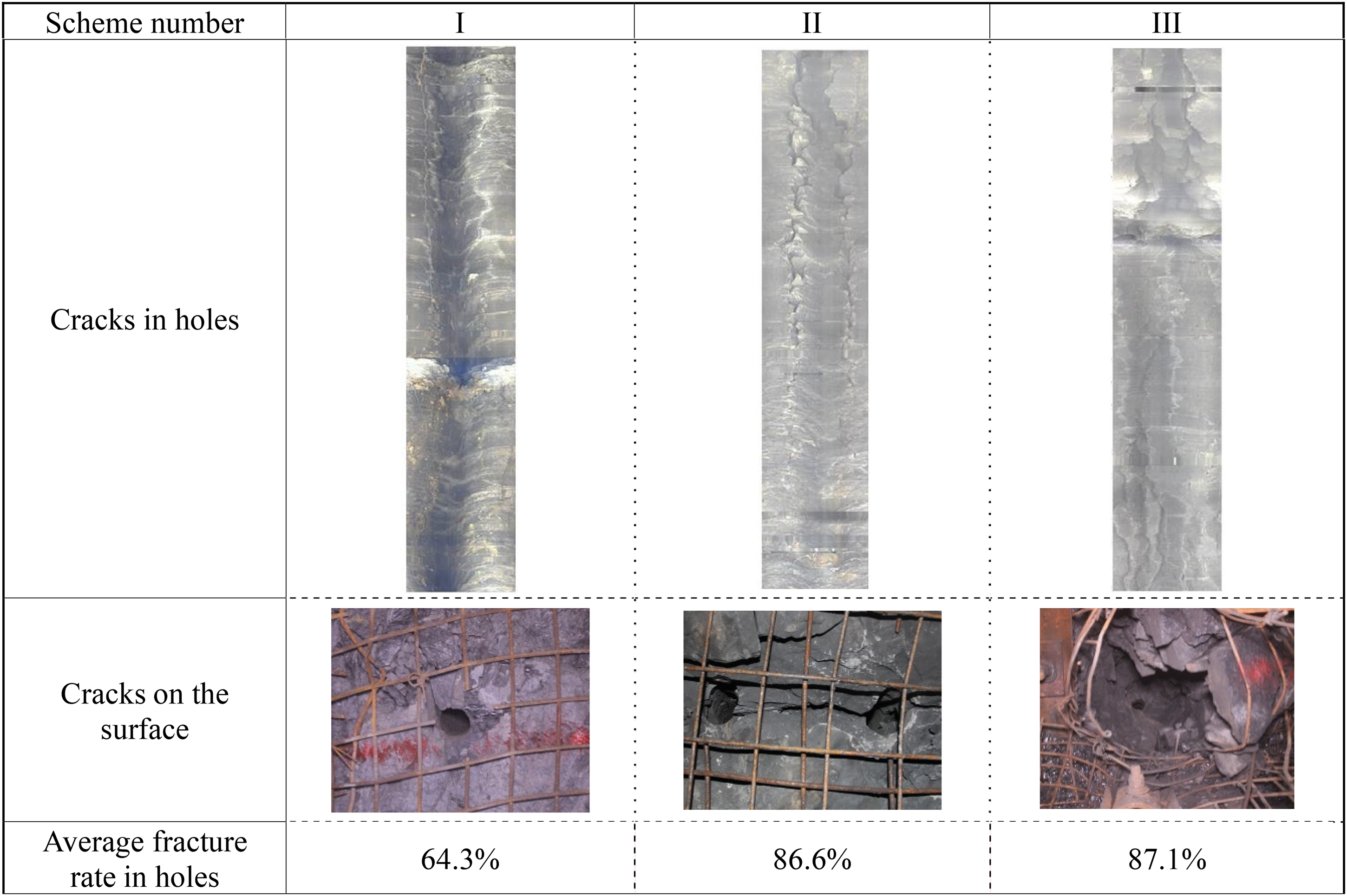
Effect of energy-accumulated blasting.
It can be seen from Figure 11 that under the “3 + 2 + 1 + 0” charging structure, two directional cracks are formed in the hole. These cracks are small and discontinuous with the average crack rate in the holes of 64.3% only. The surface of the blasting holes stays intact, and no cracks are found. This shows that directional cracks are only formed within a specific radius around the blast holes under the charging structure, but the blasting energy is insufficient to completely connect the cracks between the blast holes, limiting a good effect of roof cutting. When the “4 + 3 + 2 + 0” charging structure is adopted, two obvious and continuous cracks are formed in the hole and the average crack rate in the holes goes as high as 86.6%. The cracks on the surface of the holes are also connected with each other. The roof strata have been fully cut off, and a good effect of roof cutting is observed. Under the “5 + 4 + 2 + 0” charging structure, two or more cracks were formed in the hole. The rock was severely damaged in certain places, and the crack rate reached 87.1%. On the hole surface, a crater with a diameter of about 30 cm appeared, suggesting that, while the roof strata might be cut off under the charging structure, the explosion energy was too high to ensure the roof's integrity and stability. Therefore, the charging structure of “4 + 3 + 2 + 0” is found as the most optimal form of structure through the field test of energy-accumulated directional blasting.
Effect analysis of GERRC
According to the above-mentioned results of the study, the energy-accumulated blasting parameters for the headgate of 21304 working face are established, such as the roof cutting height of 8 m, the roof cutting angle of 15°, the distance between the blasting holes is 500 mm, the charge arrangement for each hole is designed as “4 + 3 + 2 + 0” with a sealing length of 2 meters. These investigated blasting parameters are used for the field industrial test of GERRC in the 21304 working face. The field observation results showed that after the mining of coal seam, the goaf roof collapsed rapidly along the presplitting structural plane, and the goaf gangue can timely fill the mining space to form the gangue wall (see Figure 12). This leads to effectively cutting off the relationship between the roadway roof and the goaf strata, and the roof of the retained entry forms a short-arm beam structure.
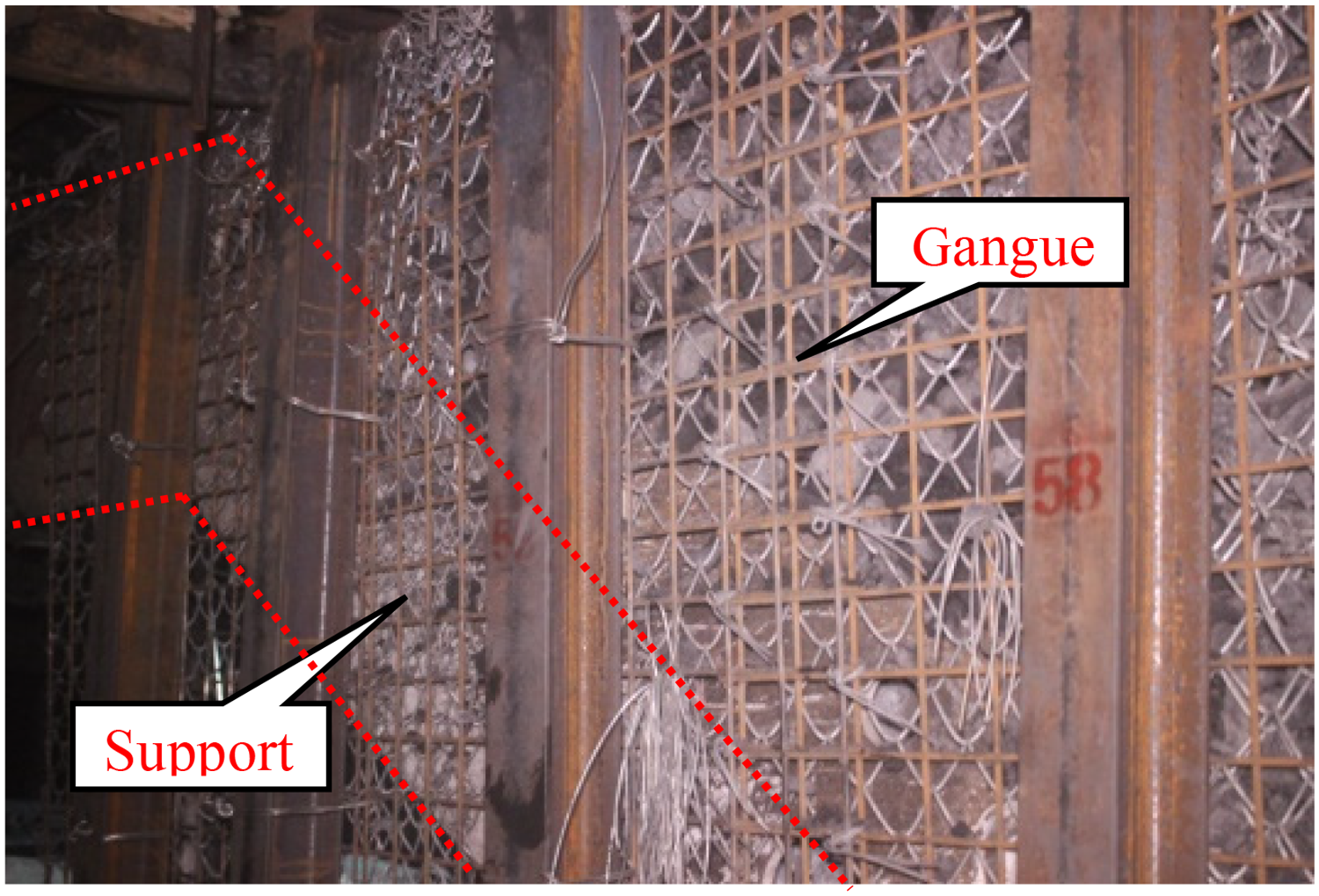
Effect of gangue collapse.
To gain a deeper understanding of the deformation patterns in the surrounding rock of GERRC and assess its impact, a series of surface displacement monitoring stations has been established at intervals of 50 meters along the headgate of the 21304 working face (Yavuz, 2004). The subsidence measurement points for the roof and heave points for the floor are positioned on the mining side, while the locations for the contractions between the ribs are set in the center of the roadway walls. As depicted in the figure, the curves illustrating the deformation of surrounding rocks at designated measuring points are presented
It can be seen from Figure 13 that the surrounding rock deformation can be divided into four stages, viz., advance influence area, severe deformation area, slow deformation area and stability area. The surrounding rock of roadway begins to deform at a distance of around 30 m in the front of the working face, and the deformation rate and the deformation of surrounding rocks are small at this stage. Observations indicate that the most significant surrounding rock deformation occurs within a distance of 0 to 96 m behind the working face, with the peak rates of convergence from the roof to the floor measuring 32 mm per day, while the contractions between the ribs reach 14.7 mm per day. Approximately 70% of the overall deformation occurs in the surrounding rocks this phase. From 96 to 291 m behind the working face, a progressively diminishing deformation rate is observed in this phase. Beyond a distance of 291 m from the working face, stability is observed in the surrounding rock. Ultimately, the roof has settled by 281 mm, accompanied by a floor uplift of 389 mm and a contraction of 343 mm between the ribs. The effect of the gangue wall and the retained entry is shown in Figure 14.
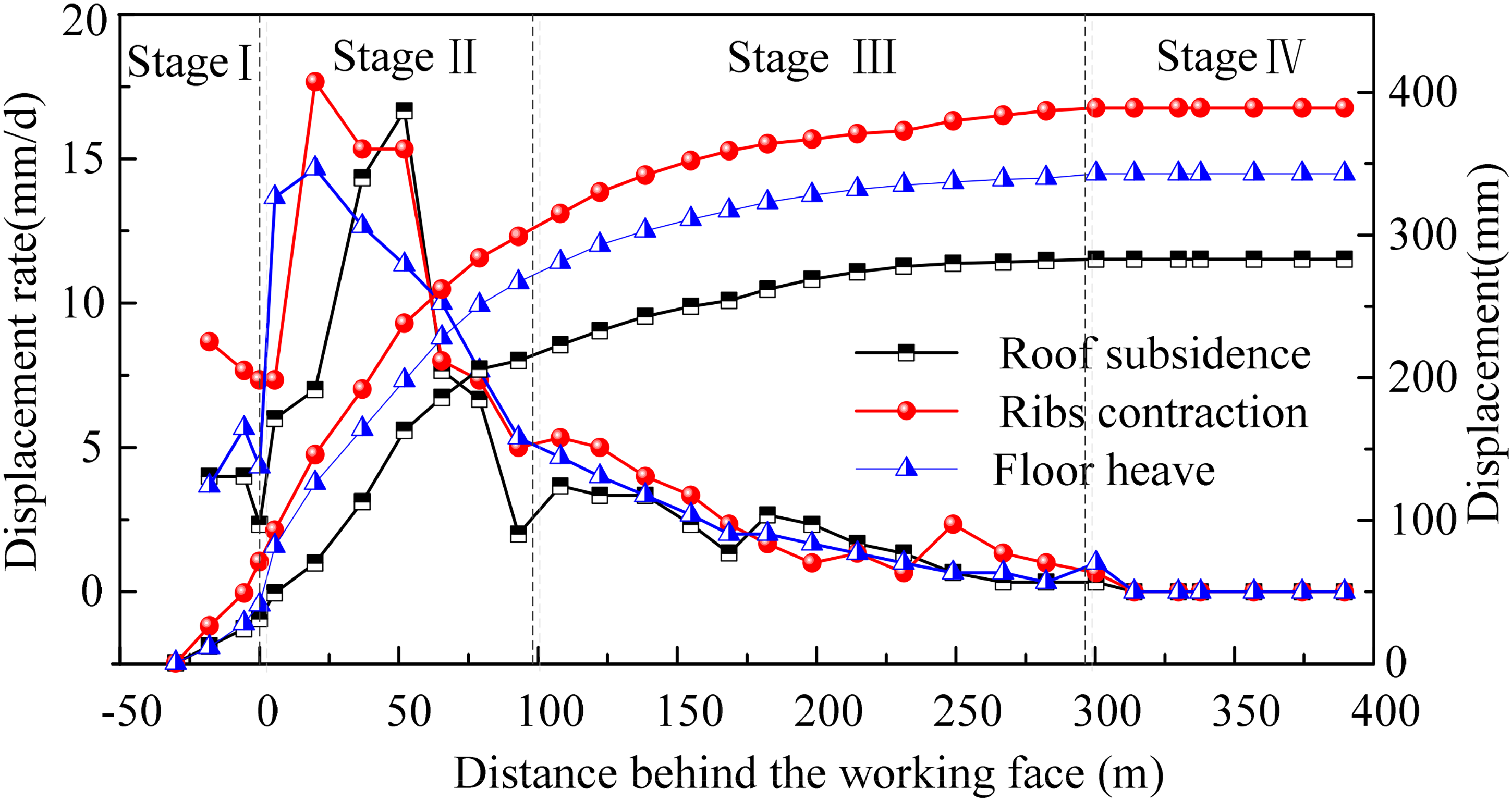
Surrounding rock deformation curve of gob-side entry retaining by cutting roof.
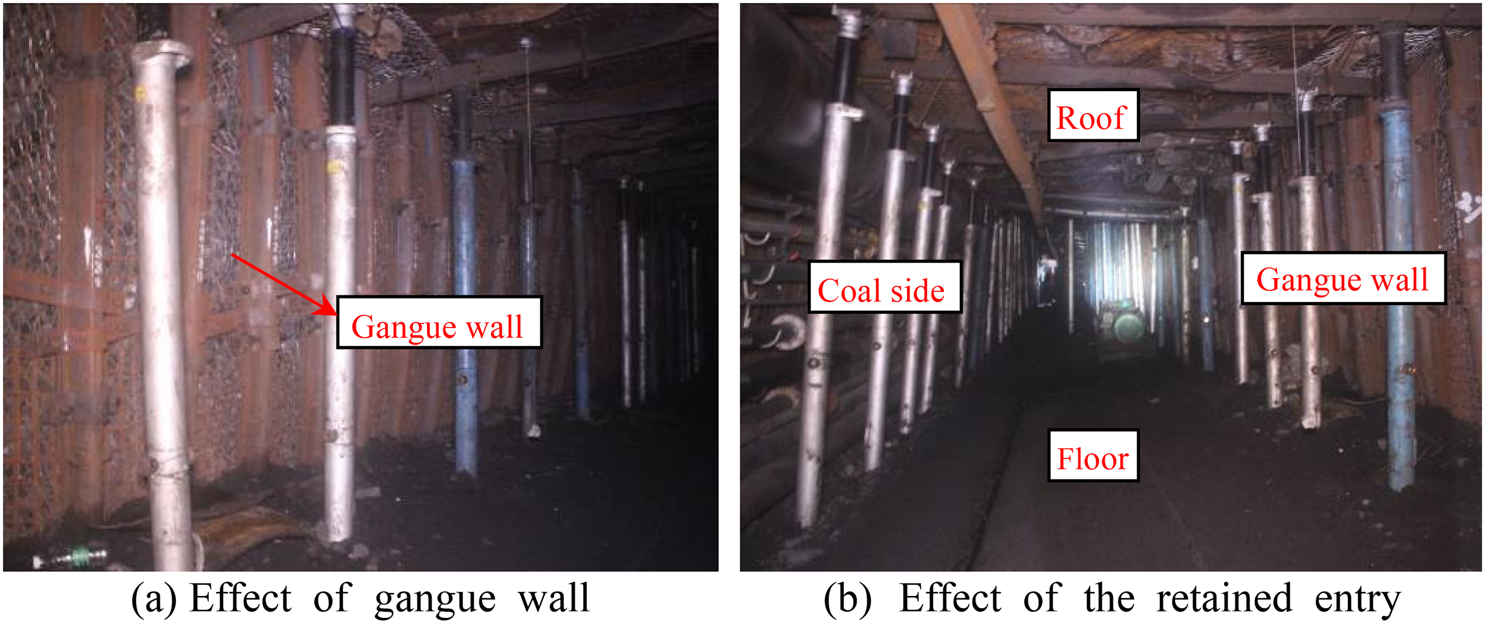
Application effect of gob-side entry retaining by cutting roof.
A headgate measuring 1200 meters has been effectively maintained in the 21304 working face. Except that the floor of some sections needs to be caunched, the majority of the retained entry is adequate to satisfy the basic standards for the next working face, which suggests the soundness and practicality of the parameters for energy accumulation blasting.
Conclusions
The research results are significant for improving the theoretical and technical system of GERRC, the specific conclusion is as follows:
The directional blasting technology by the accumulation of energy helps in completely fracturing the roof of the roadway along with keeping the integrity of the roof intact, which is a key to the success of GERRC. Through theoretical analysis, the directional blasting mechanics model is established and the penetration condition of damage between blasting holes is obtained. The numerical simulation results show that a tensile stress is generated on the blasting hole wall in the designated direction, and the range and strength of tensile stress gradually increase. When the tensile stress exceeds the dynamic tensile strength of the rock, directional fractures in rock are formed. With the action of the detonation stress, the length and width of directional damage in the rock mass increase continuously. Following the mining process, the roof system consisting of a “lower short beam and an upper masonry structure” is achieved through a method of controlled blasting to pre-split the roof. This significantly diminishes the lateral length of the basic roof, resulting in the establishment of a reduced length beam. and the pressure exerted on the roof is adequately alleviated. The majority of the overburden pressure is supported by the upper masonry beam, creating a low-stress environment ideal for GERRC. The combined roof structure enhances the stability of the retained entry. For the experimental analysis, the 21304 working face of Chengjiao coal mine is utilized as a case study. the parameters for directional blasting are derived from theoretical analysis and practical experiments. The blasting parameters of the tests are the roof cutting height of 8 m, the roof cutting angle of 15°, the spacing between blasting holes of 500 mm, the single-hole charge arrangement of “4 + 3 + 2 + 0,” with a sealing length set at 2 m. When the determined blasting parameters are used to retain the entry, the roof in the goaf collapsed along the structural surface formed by directional blasting and the gangues filled the entire roadway quickly. Located about 290 m behind the working face, the surrounding rock of GERRC is found to be stable, and all other indicators are found to meet the minimum requirements for the next working face.
Footnotes
Declaration of conflicting interests
The authors declared no potential conflicts of interest with respect to the research, authorship, and/or publication of this article.
Funding
The authors disclosed receipt of the following financial support for the research, authorship, and/or publication of this article: The research described in this paper was supported by the Key Research & Development and Promotion Projects of Henan Province (Grant Nos. 242102320346, 232102321009), the Key Scientific Research Projects of Henan Province Colleges (Grant No. 23A440010) and the Natural Science Foundation of Henan Province (Grant No. 232300420448).