
Abstract
During the application of gob-side entry retaining by roof cutting in inclined coal seams, the boundary conditions of the main roof in the goaf will change, resulting in the special characteristics of its fracture evolution. This article established a main roof elastic mechanics model through theoretical analysis and obtained the stress expression of any point on the main roof, analyzed the stress distribution characteristics and fracture evolution law of the main roof, finally, and revealed the unloading mechanism of the overburden in the cutting roof of goaf by combining with field mining pressure data. The results show that the stress value on the main roof is related to the dip angle, the poison's ratio, and the geometry parameters of the working face. The main roof stress presented an asymmetric distribution in the inclined direction. The fracture mode of the main roof is the “U-Y” mode under the first weighting and the “L-Y” mode under periodic breakage. The pressure on the upper part of the working face increased, while the lower part decreased according to field mining pressure data. There are two reasons for the reduction of pressure in the lower part of the working face, on the one hand, the reduction of the area of the key block A leads to a decrease in load, on the other hand, the gangue filling and supporting effect of the lower part of the goaf. The surrounding rock of the gob-side entry is not obviously affected by the dynamic pressure, and the deformation is small, achieving a good retaining effect.
Keywords
Introduction
Non-coal pillar mining is an economic and valuable mining method, it not only allows for the recovery of the coal pillar resources between working faces but also shortens the process connection time between excavation and mining (Lu, 1981; Zhang et al., 2014). But traditional non-coal pillar mining, including gob-side entry support (Han et al., 2015; Tan et al., 2015), goaf filling (Jiang et al., 2020; Zhang et al., 2011b), and gob-side entry driving (Bai et al., 2015; Zhang et al., 2018), has the disadvantages of the impact on mining speed and the increase in cost. An innovative no-pillar mining method had been proposed(He et al., 2015), named gob-side entry retaining by roof cutting (GERRC), that has simpler procedures and is safer and more efficient (Wang et al., 2018; Zhang et al., 2011a). GERRC has been implemented in more than 500 working faces in China; this technology offers favorable economic benefits and has broad application prospects.
The technical principles of GERRC are that carrying out directional pre-splitting blasting in advance in working face to form a pre-splitting structural plane and make the roof rock of goaf collapse along the structural plane to automatically form a roadway wall. GERRC includes three key technologies: first is the use of constant resistance and large deformation anchor cable in the roadway to provide high prestress active support for the roof. The second is to use the directional pre-splitting blasting technology to form a slit fracture surface between the advanced reserved roadway and the advanced coal roof in the working face, cut off the stress transfer between them, improve the stress state of the surrounding rock of the reserved roadway, and reduce the influence of periodic pressure on the deformation of the roof. Third, the gangue rib is maintained with gangue retaining technology to prevent horizontal displacement of the gangue rib and ensure the stability of gangue rib, and the temporary support was used to reduce the effect of mining on the entry roof. The technology is shown in Figure 1.
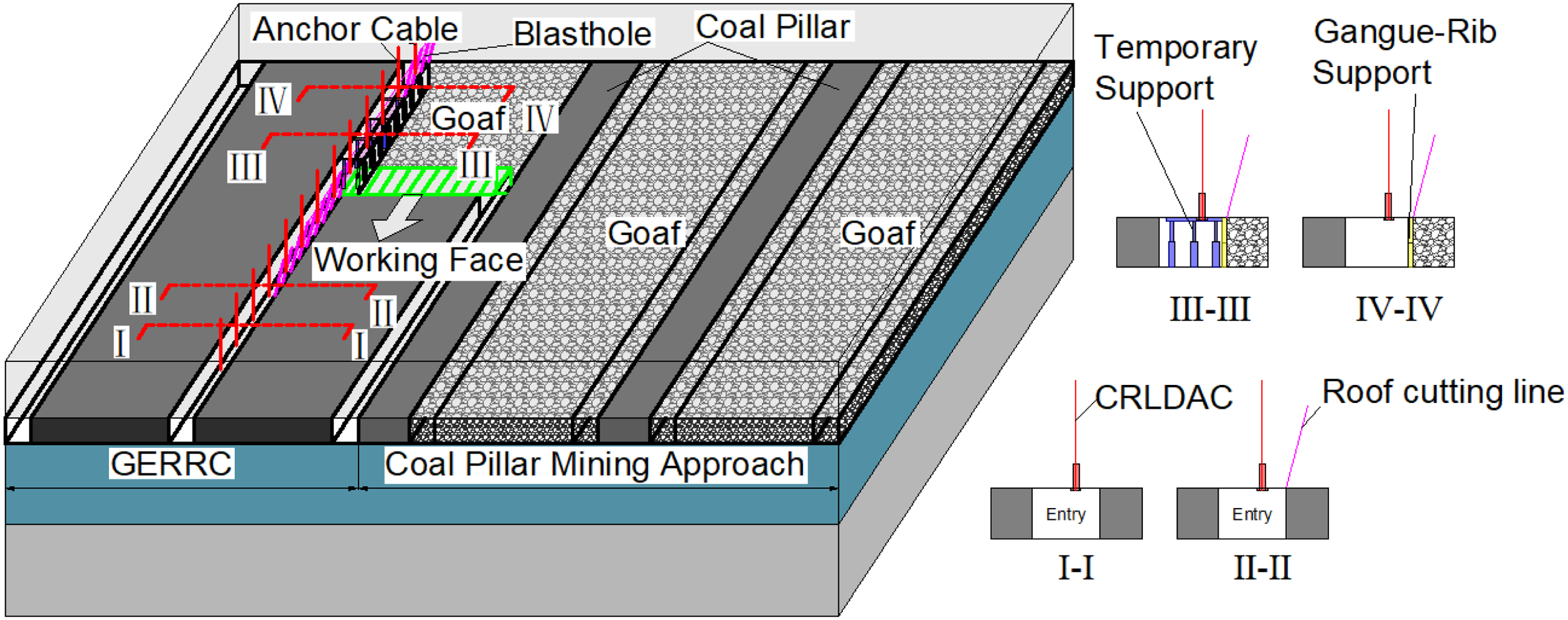
The technical principles gob-side entry retaining by roof cutting (GERRC).
The research on GERRC mainly focuses on applications under different geological conditions and includes the pre-splitting blasting parameters and blasting methods in hard roofs, soft roofs, and composite roofs (He et al., 2019; Hu et al., 2019b; Ma et al., 2019); support parameter and method selection in thin coal seams, medium-thick coal seams, and thick coal seams (Gao et al., 2017; Guo et al., 2016; He et al., 2018b; Sun et al., 2014); temporary support methods for the roofs of shallow and deep coal seams (Gao et al., 2019b; He et al., 2018c; Wang et al., 2020); and cutting angles and cutting depth parameters for near-horizontal and inclined coal seams (Gao et al., 2019a; Hu et al., 2019a). Theoretical research on GERRC is limited (He et al., 2022; Li et al., 2023; Liang et al., 2023). The mechanism of pressure relief of gob-side roofs has been studied, and several surrounding rock structure-roadside support body mechanical models have been established to design roadway-side supporting resistance (He et al., 2017a). The study results of the stress distribution and development before and after roof cutting in both the mining face and the entry indicate that the mine pressure at the working face and the retained entry changes considerably before and after roof cutting (He et al., 2017b).
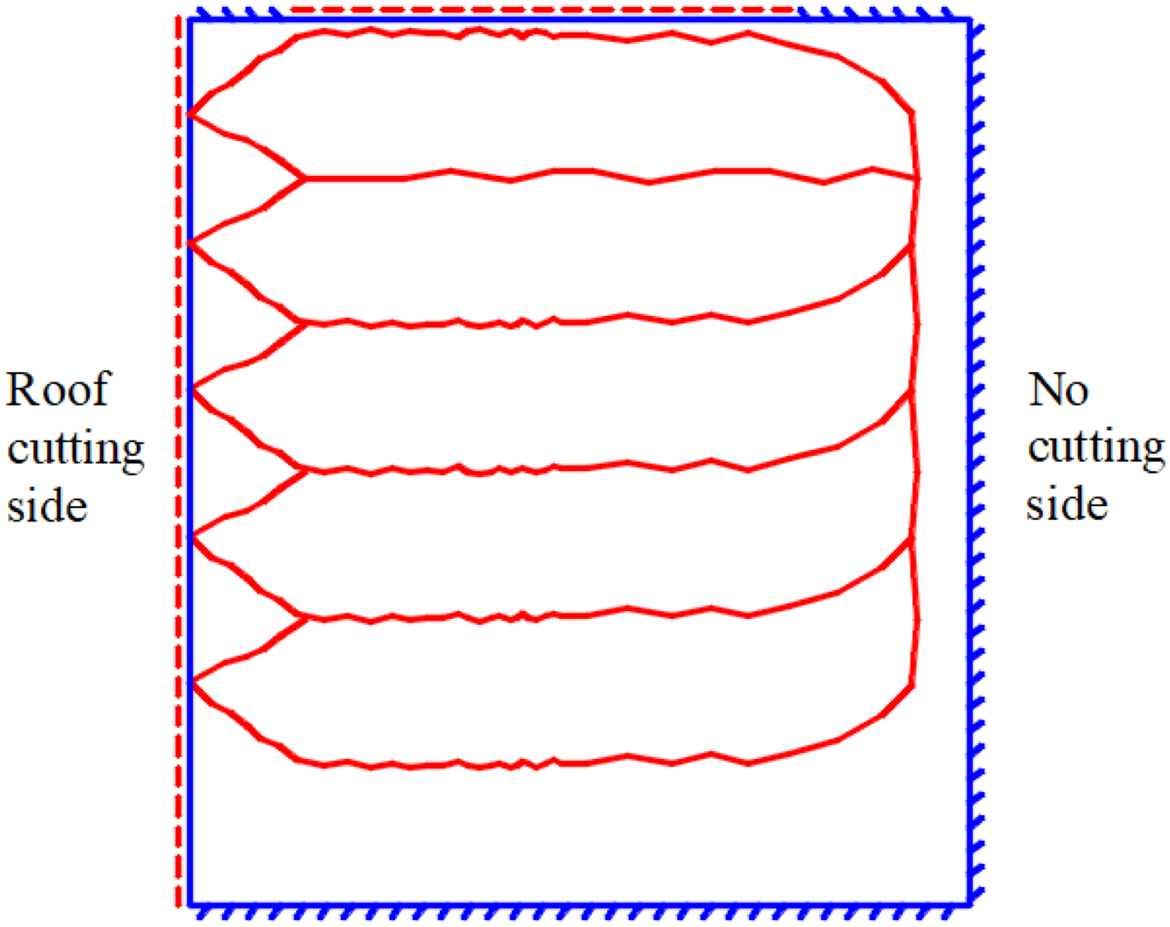
During the application of GERRC in inclined coal seams, according to the thin plate theory, the stress condition of the main roof before the first weighting can be regarded as an elastic thin plate with one edge simply supported and three edges fixed supported, and the condition can be changed to the elastic thin plate with two edges simply supported and two edges fixed supported during the periodic fracture. Because the maximum amount of sinking in the basic top bending process is much smaller than the thickness of the thin plate, the stress condition can be determined according to the small deflection bending problem of an elastic thin plate. The change of the stope roof structure after roof cutting will affect its stress distribution characteristics and the process of breaking and caving. The boundary conditions of the main roof before and after the first weighting are shown in Figure 2.
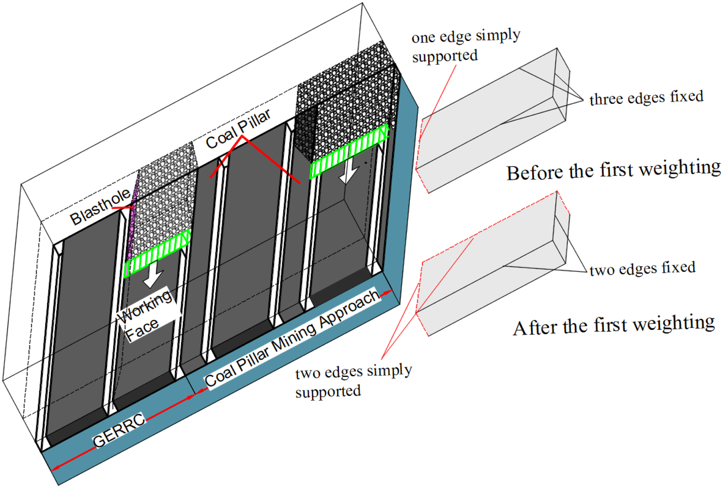
Boundary conditions of the main roof.
Although many technological studies have been conducted under various geological conditions, the effects of roof cutting on the fracture evolution of the main roof are still unclear (Nie et al., 2022; Tang et al., 2022). This article provides a mechanics model of the main roof in an inclined coal seam and analyses the fracture evolution of the main roof and ground pressure with actual cases.
Mechanics analysis of the main roof
Mechanics model of the main roof
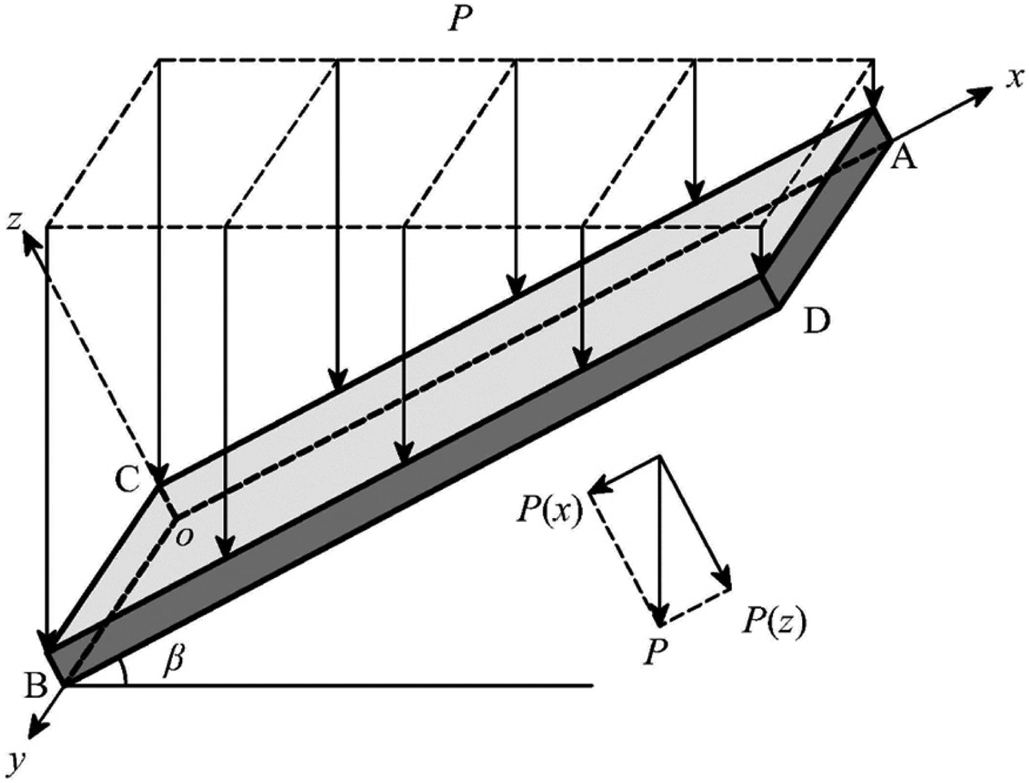
The mechanical model of an elastic thin plate for inclined coal seam mining is shown in Figure 3, where the long direction of the working face is the x-axis, the advancing direction of the working face is the y-axis, and the direction is perpendicular to the top plate is the z-axis; the length of the plate is a, the width is b, and the thickness is c; the dip angle of the coal seam is β; the vertical load P of the thin plate can be decomposed into the stress superposition of the lateral load P(z) and the longitudinal load P(x) in the z- and x-directions, and the large inclination angle under the combined longitudinal and lateral loads can be calculated as the stress expression of the points located directly on the coal seam.
Mechanical model of the elastic thin plate for inclined coal seam mining.
According to the theory of elastic thin plates, when the mechanical model produces small deflection bending, only the small deflection bending differential equation needs to be satisfied

Stress condition of the main roof before the first weighting
When roof-cutting technology is adopted in inclined coal seams, the roof between the roadway and working face is artificially cut off in advance so that the roadway can be preserved after mining and to change the boundary conditions on one side of the roadway. Before mining, the main roof with one edge simply supported and three edges fixed supported, loaded above and supported below, is in a super-statical state. During mining, the coal is mined, and the main roof with one edge free and three edges fixed supported, and loaded above are in a transition state. Before the main roof fracture, as the broken coal rock slides, the main roof is supported near the roof cutting and is in an unsteady state of one edge simply supported and three edges fixed supported, and loaded above. Then, the displacement boundary conditions of the main roof before fracture are


Stress condition of the main roof after the first weighting
After the first weighting, the main roof is in the stage of periodic cyclic pressing, where two adjacent edges are simply supported and the other two adjacent edges are fixed supported. Then, the displacement boundary conditions are


Case study
Geological background and basic parameters of the main roof rock
The Fucheng Mine is located in the city of Ordos, Inner Mongolia, China. The 1906S working face is located at the south wing of the first mining area at the +150 level, to the west is the 1905S mined area, to the east and south are the unmined areas of the nine-layer coal and to the north is the 1906S withdrawal channel. The working face has a strike length of 1176 m, a slope length of 185.7–193.6 m, and an average slope length of 190.3 m. The coal seam inclination angle of the working face is between 22° and 32°, and the average coal seam inclination angle is 28°. The roof lithology of the upper coal seam is dominated by limestone (four ash); part of this roof contains a thin layer of mudstone or carbonaceous mudstone. The rock samples were drilled at the site, and were sealed at the site to ensure the same humidity and moisture content as the site. The physical and mechanical parameters of the main roof can be obtained after the rock mechanic experiment, which are shown in Figure 4 and Table 1.
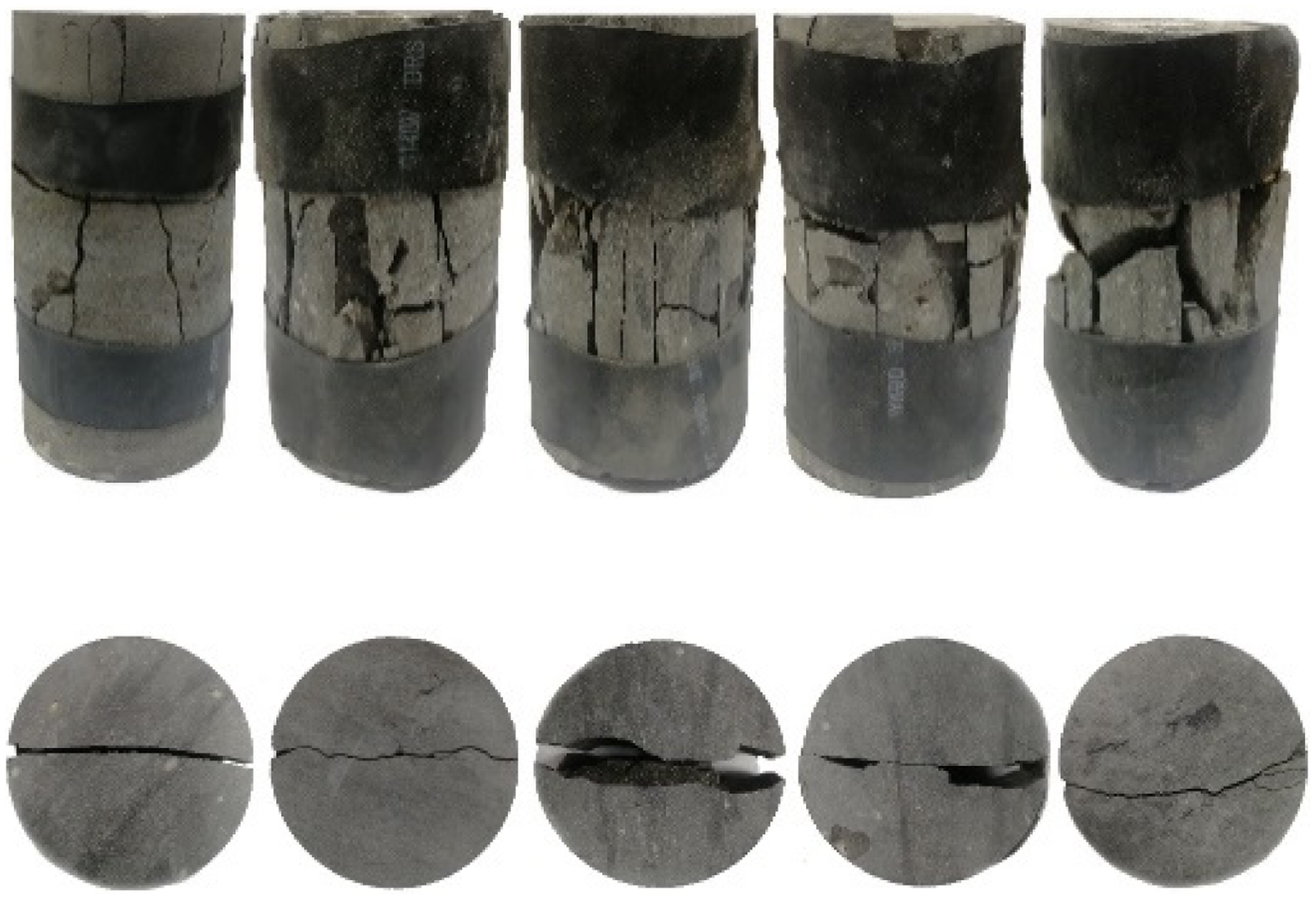
Uniaxial compressive and Brazilian splitting test of limestone.
Physical and mechanical parameters of limestone.
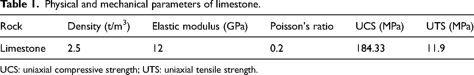
UCS: uniaxial compressive strength; UTS: uniaxial tensile strength.
Fracture criterion of the main roof
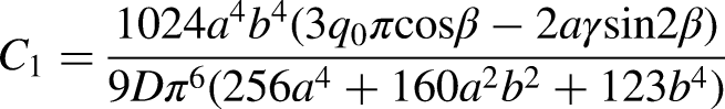
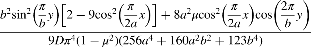
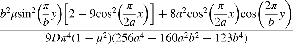
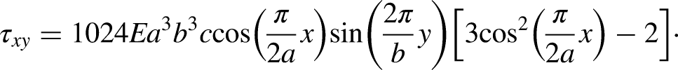
The following equation is substituted into the principal stress calculation formula, and the principal stress expression for any point of the inclined trapezoidal thin plate is obtained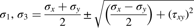
According to the theory of maximum tensile stress, the tensile stress of the principal stress value σ3 is compared with the tensile strength of the rock mass of the roof. If the tensile stress reaches or exceeds the tensile strength of the rock mass, tensile failure of the roof occurs. The roof rock layer fracture criterion is S(x, y) = σ3/σt. The stress proportional function S(x, y) can be used to determine the coordinate point (x, y) at which the main roof undergoes tensile failure. When S(x, y) ≤ξ, tensile failure occurs at point (x, y), and ξ is the critical breaking coefficient.
Fracture evolution of the main roof in the first weighting
According to the pressure observation results of the working face of the Fucheng Mine, the initial step of the main roof is 40 m, a = 190 m, b = 40 m, c = 10 m, β = 28°, E = 1.2 × 10⁴ MPa, μ= 0.2, and γ = 25 kN/m3, and [σt] = 11.9 MPa, and the tensile stress distribution map of the upper and lower plates and the contour map of f(x, y) is drawn.
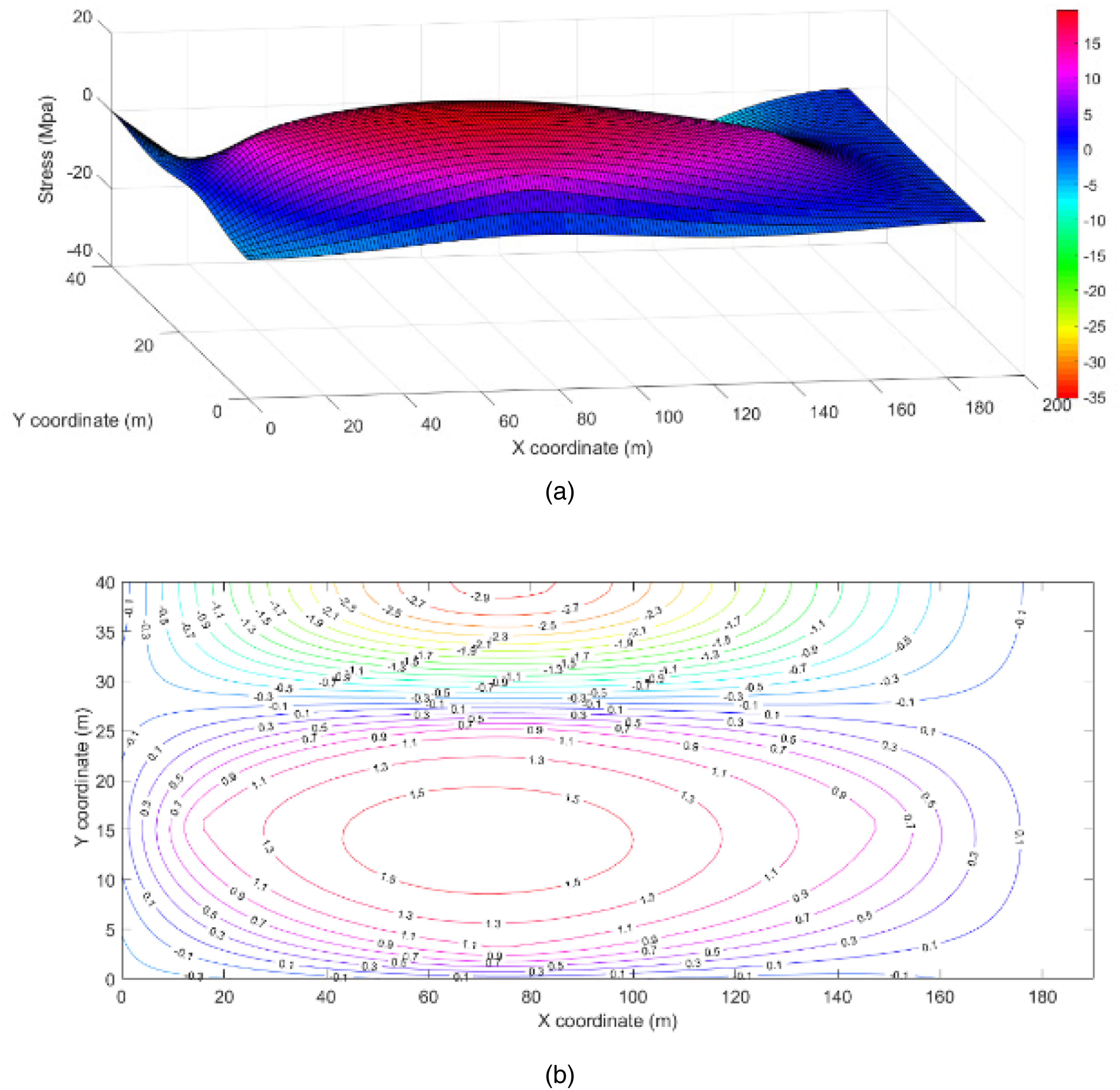
The characteristics of the stress distribution directly on the top surface are shown in Figure 5(a). The maximum tensile stress in the x-direction is formed at x = 74 m on the two long sides of the upper surface of the rock formation. The maximum tensile stress in the y-direction on the short side of the non-cut top is located at y = 20 m, and the maximum tensile stress in the y-direction on the short side of the cut top is located at y = 10 and y = 30 m. The inner surface of the rock layer is a compressive stress area. Figure 5(b) shows that when the main roof is broken for the first time, the critical breaking coefficient ξ = −0.1. In the advancing direction of the working surface, the stress on the surface of the main roof is symmetrically distributed. In the inclined direction of the working surface, the stress on the surface of the main roof is asymmetrically distributed, and the tensile stress concentration area is formed on the basic top surface.
The stress distribution characteristics of the top surface in first weighting: (a) stereograph; (b) contour map.
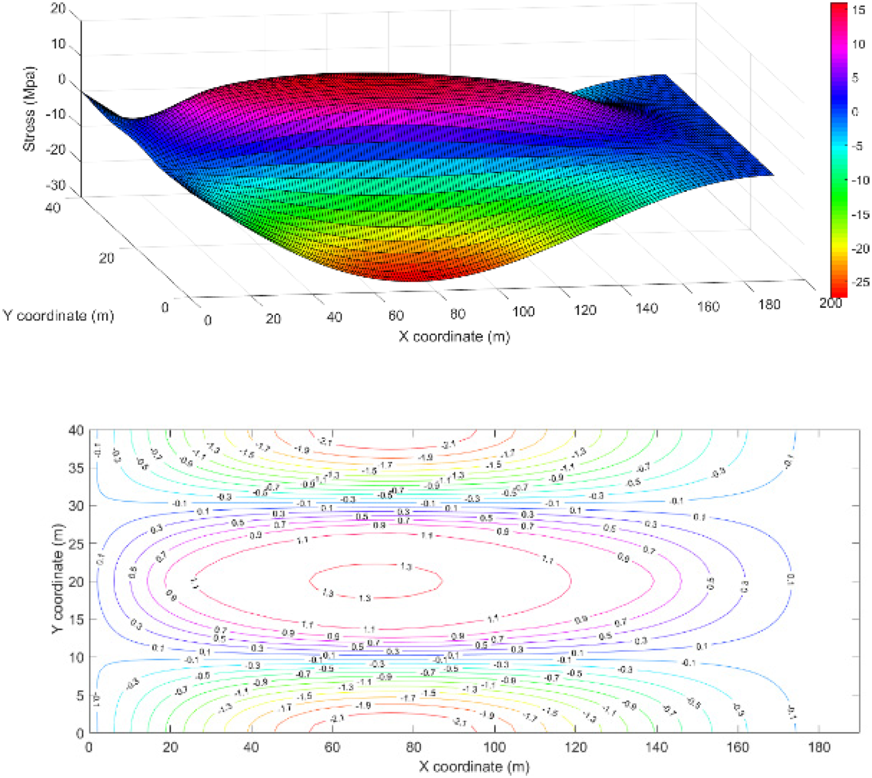
The stress distribution characteristics of the bottom surfaces are shown in Figure 6(a). The two long sides of the lower surface of the rock formation are compressive stress zones, and the maximum tensile stress is located at x = 74 m and y = 20 m. The maximum tensile stress in the y-direction on the short side of the non-cut top is located at y = 20 m, the maximum tensile stress in the y-direction on the short side of the cut top is located at y = 10 and y = 30 m, and all the upper surface of the rock formation is within the tensile stress area. As seen from the contour diagram in Figure 6(b), when the main roof is broken for the first time, the critical breaking coefficient ξ = −0.1. In the advancing direction of the working surface, the stress on the surface of the main roof is symmetrically distributed. In the inclined direction of the working surface, the stress on the surface of the main roof is asymmetrically distributed, and the tensile stress concentration area is formed on the inside of the basic top.
The stress distribution characteristics of the bottom surface in first weighting: (a) stereograph; (b) contour map.
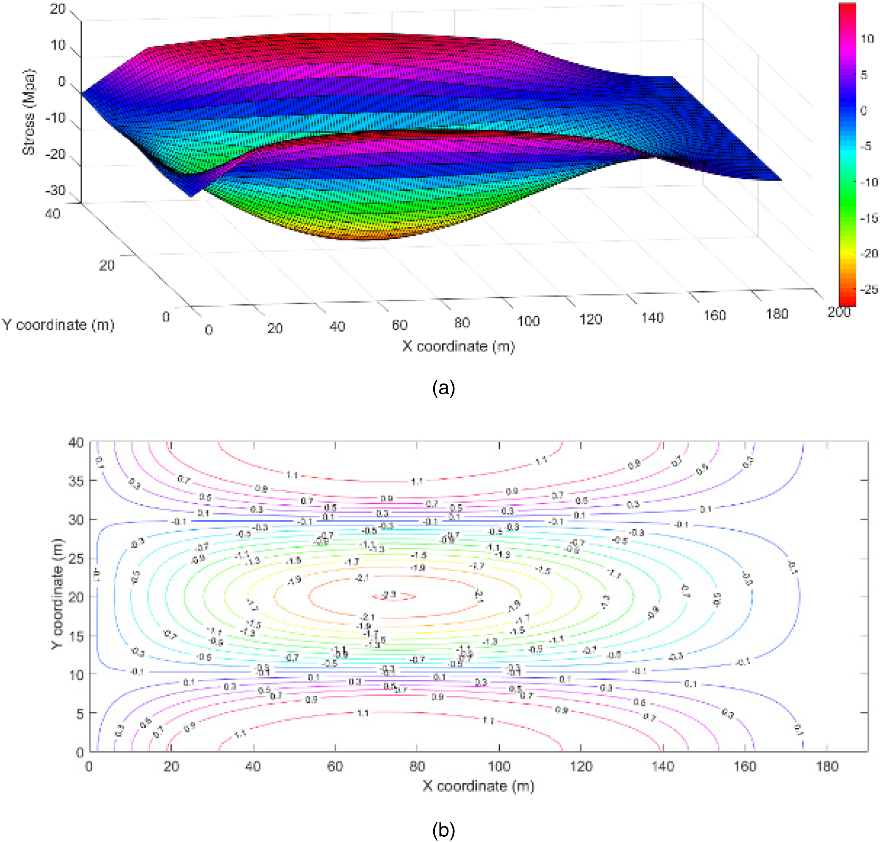
Because the tensile strength of the rock mass is much lower than the compressive strength, the maximum tensile stress of the thin plate model is located at y = 74 m on the two long sides of the upper surface, so the rock layer will first form cracks that expand to both sides and subsequently, the damage will occur. Regarding the short side of the cut-top side on the rock formation (i.e. along the empty roadway), the maximum tensile stress on the lower surface of the rock formation is smaller than the previous two stresses. As the working face advances, the central area of the basic top rock formation is x = 74 m, y = 20 m. The tensile stress here exceeds the tensile strength limit, and a crack is formed. The middle and upper layers of the rock formation are also affected by the tensile stress in the x-direction. At this time, a “U”-shaped crack is formed around the main roof, and a middle part is formed in the rock layer. An approximately “Y”-type fracture occurs, as the fracture expands and penetrates the main roof for the first time. Unlike the “O-X”-type fracture of horizontal and near-horizontal coal seam roofs, the fracture of inclined coal seam roofs can be called a “U-Y”-type break. The fracture evolution of the main roof in the first weighting can be seen in Figure 7.
The fracture evolution of the main roof in first weighting.
Fracture evolution of the main roof under periodic breakage
Under the same physical and mechanical parameters, the stress distribution characteristics of the top and bottom surfaces of the basic top during periodic breakage are analyzed. Figures 8 and 9 show that the maximum tensile stress around the edges of the main roof is located in the center area of the long side fixed on the upper surface, followed by that in the center area of the short side on the left side of the rock layer (at the upper end of the rock layer). They are all compressive stress zones; the stress distribution characteristics of the central area of the rock formation are basically the same as those at the initial fracture. The cracks first occur at the fixed edge of the rock layer and second at the upper edge of the short edge. The cracks expand and penetrate, eventually forming a semi-“L-Y"-type periodic break with a large dip in the roof of the coal seam.
The stress distribution characteristics of the top surface in periodic breakage: (a) stereograph; (b) contour map.
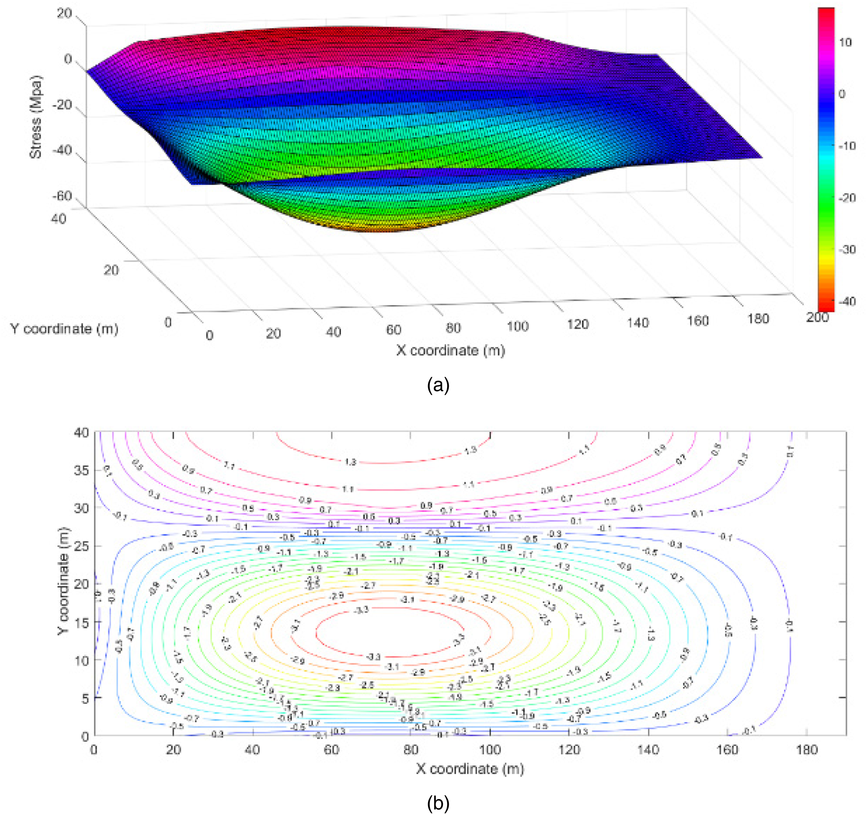
The stress distribution characteristics of the bottom surface in periodic breakage: (a) stereograph; (b) contour map.
The elevation angle of the large-inclined working face also greatly influences the stress distribution of the main roof during periodic breakage. The maximum tensile stress of the rock stratum tendency and strike during the high-inclined elevation mining reaches 1.2–1.3 times that of high-inclined elevation mining, that is, the elevation. The breaking limit is reached earlier in the basic top rock strata than in the lower mining area, the breaking step is shorter in the lower mining area, and the pressure appears to be weaker in the lower mining area, which is consistent with the conclusions of the previous mechanical analysis. The fracture evolution of the main roof in periodic breakage can be seen in Figure 10.
The fracture evolution of the main roof in periodic breakage.
Field test result
Hydraulic support pressure characteristics in the working face
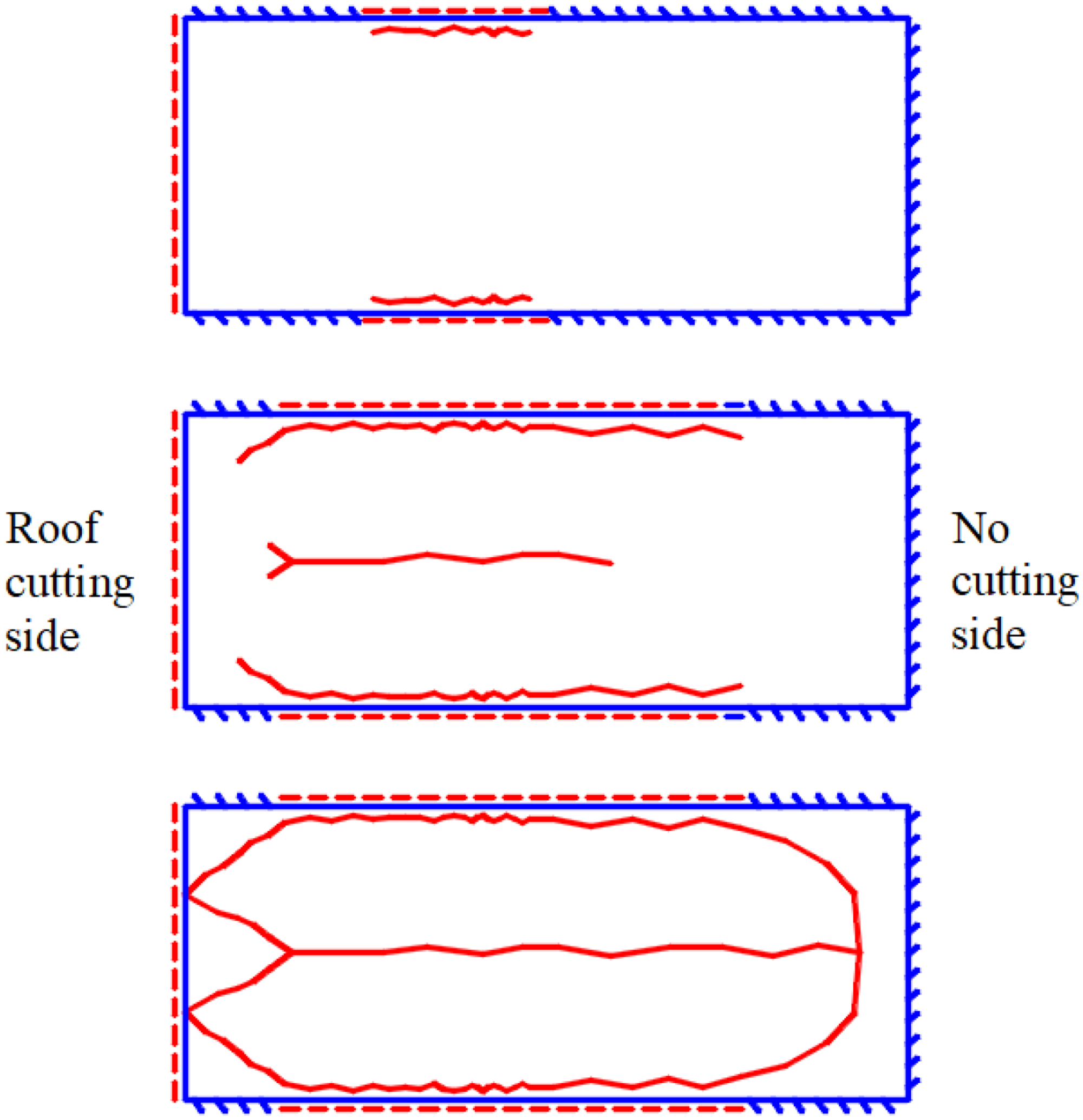
In the 1906S working face of the Fucheng Coal Mine, a GERRC field test was carried out after a distance of 98 m to the open-off cut, that is, the first 98 m of the entry without retaining, was achieved. A total of 110 hydraulic supports are arranged in the working face, numbered from small to large in the lower entry, as shown in Figure 11.
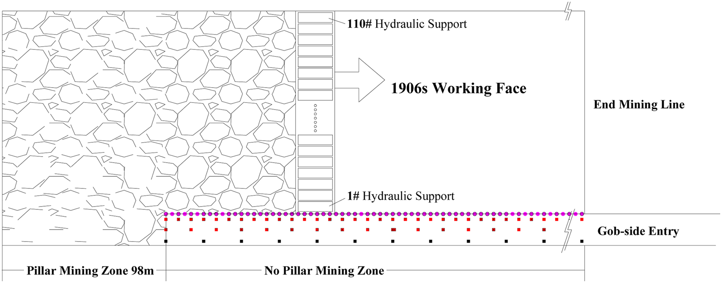
The mining zone and hydraulic support design in 1906S working face.
A total of three hydraulic supports, #4, #10, and #16, are selected for the analysis of the mine pressure near the gob-side entry. The load curves of hydraulic supports #4, #10, and #16 are shown in Figure 12, and the support surface pressure and the step pressure of the working face are obtained. The support pressure of the no pillar mining zone is reduced by 4.34 MPa compared with that in the pillar mining zone, a decrease of 10.3%. The average pressure is reduced by 3 MPa, a decrease of 10%.
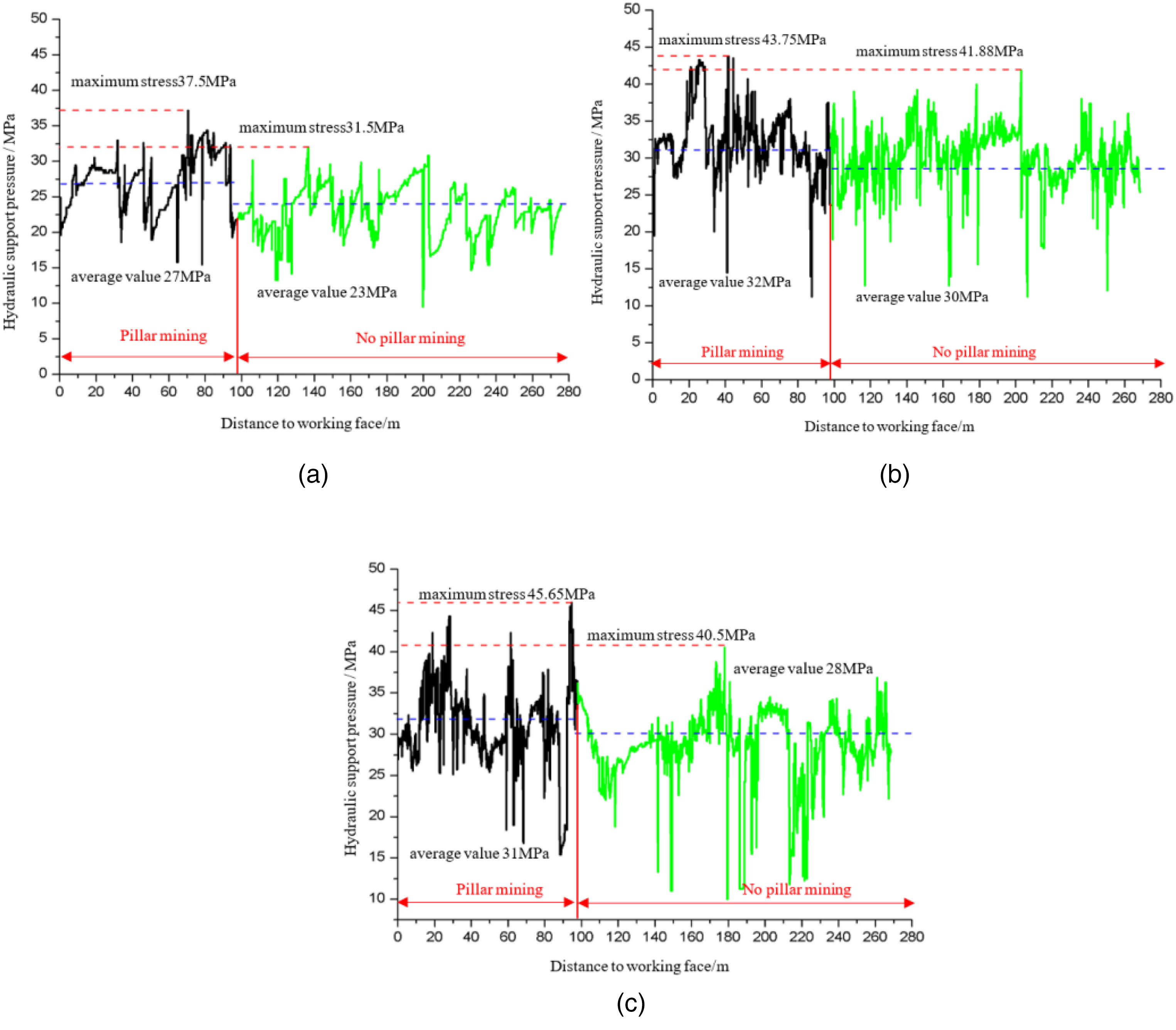
Load curve of hydraulic support near roof cutting in working face: (a) hydraulic support 4#; (b) hydraulic support 10#; (c) hydraulic support 16#.
Table 2 shows the periodic breakage mining length in the no pillar mining zone increases by 5.0 m compared to that in the pillar mining zone. After the roof is cut on one side of the roadway, the gangue in the goaf is more likely to collapse, and under the action of the gangue support structure, a good bearing effect is formed on the cut roof side of the goaf, which reduces the working pressure of the hydraulic support under the working face and restricts the basic roof. Breaking and falling, the breakage and slippage occurs after the overall area of the basic roof increases and meets the breaking conditions, which increases the periodic pressure stepping distance of the lower part of the working face.
Periodic breakage length near roof cutting in working face.
The 110 working face hydraulic supports are equally grouped and divided into upper, middle, and lower parts, and the average pressure is calculated, as shown in Figure 13. After the roof is cut, the stress distribution in the inclined direction of the working face changes. Under the condition of coal pillar mining, the pressure of the working face is mainly concentrated in the middle and lower parts and transfers to the middle and upper parts of the working face after the roof is cut. The upper pressure increases by 4.5%, the middle pressure decreases by 4%, and the lower pressure decreases by 18%. After the roadway is roof cut, the position of the roof fracture in the goaf shifts from the upper middle to the lower middle, which is the root cause of the changes in the upper and lower stress distributions.
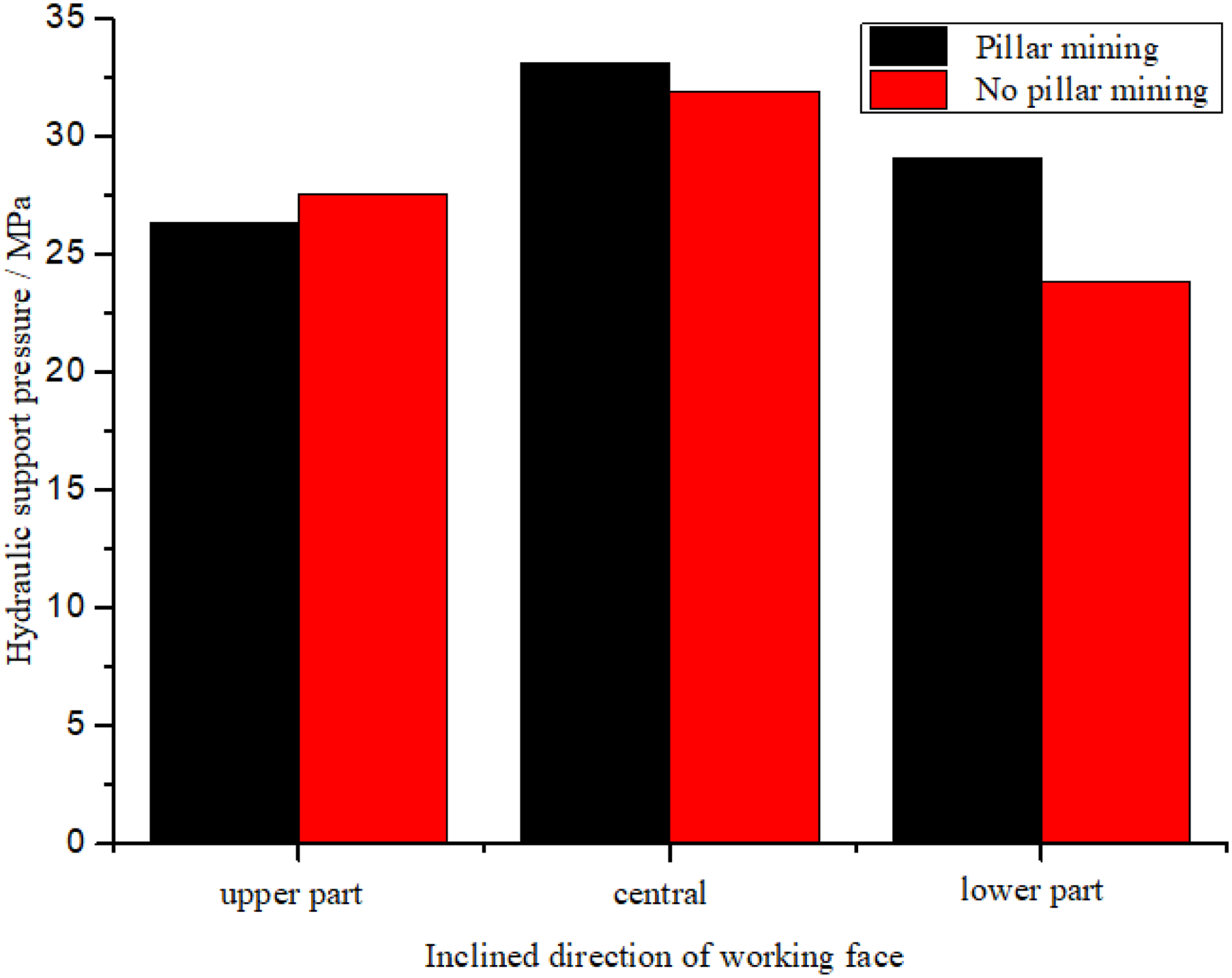
The stress distribution in the inclined direction of the working face.
Surrounding rock convergence of gob-side entry
The convergence characteristics of its roof, floor, coal rib, and gangue rib obtained from the deformation monitoring of the surrounding rock of the retaining entry are shown in Figure 14. When the surrounding rock deformation is stable, the deformation quality of the roof and the floor is close, and the deformation of the gangue rib is approximately twice that of the coal rib. The deformations from large to small are the floor (234 mm), the roof (224 mm), the gangue rib (93 mm), and the coal rib (43 mm). The severity of the surrounding rock deformation is affected by the mining pressure, and the roof and floor pressures are significantly more severe than those of the two ribs. The ground pressure severity is in the order of the roof, floor, gangue rib, and coal rib. The time sequence of the surrounding rock stability is the gangue rib, roof, coal rib, and floor.
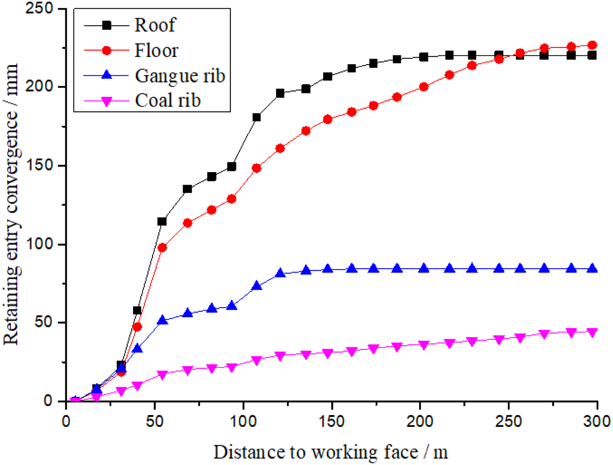
Surrounding rock convergence of gob-side entry retaining by roof cutting (GERRC).
The deformation of the surrounding rock is one of the ways that ground pressure appears. The larger the deformation rate is, the more violent the ground pressure; that is, the more violent the roof-breaking movement. According to Figure 15, the deformation rate of the retaining entry surrounding rocks first increases, then decreases, increases again, and finally stabilizes. The roof sinking rate, floor heave rate, and gangue rib movement exhibit two obvious peak points, but the coal rib does not. The first peak point is located 30 m from the lagging working face, and the second peak point is located 120 m from the lagging face. The two peak points represent the two dynamic pressure processes. The roof has undergone two violent movements: the first is the breakage and falling of the direct roof, and the second is the breakage and spin of the main roof.
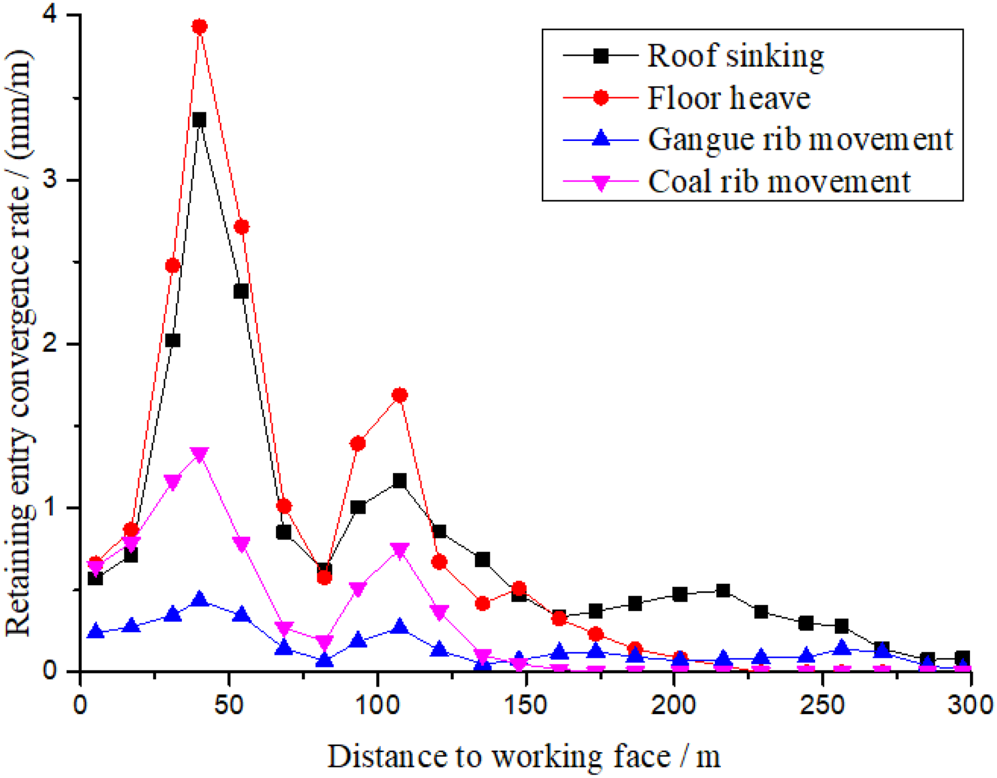
Surrounding rock convergence rate of gob-side entry retaining by roof cutting (GERRC).
Discussion
There are two reasons for the reduction of pressure in the lower part of the working face, on the one hand, the reduction of the area of the key block A leads to a decrease in load, on the other hand, the gangue filling and supporting effect of the lower part of the goaf. The braking mode of the main roof after roof cutting is “L-Y.” After the break, the triangular arc block of the main roof breaking becomes a triangular block on the roof-cutting side, and the side length collapses at half the step distance. A smaller area of the key block A reduces the effective load of the hydraulic support on the working face, which is manifested by a decrease in the working face pressure on the roof-cutting side, while the effective load on the middle and upper parts of the relative working face increases. After the goaf roof breaks and collapses in the middle and lower part of the working face, the collapsed gangue slips down, hits the gangue retaining structure, and piles up, gradually filling. The goaf on the roof cutting is filled in three stages and is ultimately stable. The gangue rib forms an arched structure with the roof of the roadway, forming a stress balance arch in the rock body. The stress balance arch is composed of three parts: an anti-dipping rock block, a triangular block A, and the roof-cutting short beam. The supporting force provided by the stress-balanced arch on the roof-cutting side reduces the load on the hydraulic support. Therefore, after the roof is cut, the change in the slope failure mode and the formation of the stress balance arch reduce the pressure on the cutting seam side of the working face, which is beneficial for the stability of the coal wall and roadway.
The existence of the stress balance arch has a positive effect on the stability of the surrounding rock of the roadway. The stress-balanced arch, the gangue in the goaf of the arch, and the support in the roadway constitute a balance system. Through the provision of a certain support resistance to the roof of the roadway and the gangue rib, the stability of the roadway along the gob can be realized. The roof-cut top short boom beam of the roadway has a self-supporting ability, which hinders the rotation and deformation of the roof, and the roadway can be stabilized through the provision of a small supporting force. The roadway gangue gang is composed of broken gangue, and the internal porosity is high. The gangue can move only by overcoming friction. Therefore, the load-bearing capacity of the gangue sidewall is poor, and lateral movement and bulge are easily produced under the vertical load of the roof. The stress balance arch effectively isolates the internal and external gangue, and the gangue retaining capacity provided in the roadway needs to overcome only the lateral pressure generated by the internal gangue weight of the stress balance arch and part of the load transmitted by the stress balance arch. The stability of the gangue gang is very important to the stability of the stress balance arch structure. If the gangue gang loses stability, the triangular slab on the cut-top side will collapse, leading to the instability of the roadway roof. Therefore, the support strategy of the roadway along the goaf ensures the stability of the gangue gang first and then the roof stability.
Conclusion
Established a mechanical model of the main roof of gob-side entry retaining by roof cutting. According to the stress expression of any point in the plate with different roof cut forms above, it can be seen that the stress value on the plate is related to the dip angle of the coal seam, the Poisson's ratio of roof strata, the dip length of working face and the advancing distance.
The fault line of main roof fracture evolution at first weighting is “U-Y,” a “U”-shaped fault zone is formed on the upper plate surface while a “Y”-shaped fault zone is formed on the lower plate surface. And the fault line of main roof fracture evolution at periodic breakage is “L-Y,” a “L”-shaped fault zone is formed on the upper plate surface while a “Y”-shaped fault zone is formed on the lower plate surface.
According to a field test, the high-pressure distribution in the inclined direction of the working face shifts upward. The pressure on the upper part of the working surface increases, while the lower part decreases, the peak pressure of the working face is reduced to 30 MPa, and the periodic breakage mining length is increased to 24 m. The surrounding rock of the gob-side entry is not obviously affected by the dynamic pressure, and the deformation is small, achieving a good retaining effect.
Footnotes
Declaration of conflicting interests
The author(s) declared no potential conflicts of interest with respect to the research, authorship, and/or publication of this article.
Funding
The author(s) received no financial support for the research, authorship, and/or publication of this article.