
Abstract
Nanoiron colloid is remarkably suitable for medical, engineering, and other applications because it exhibits excellent properties such as nontoxicity, biocompatibility, and high chemical stability. Because no studies have examined preparation of nanoiron colloid through electric spark discharge method, an electrical discharge machining system for preparing nanoiron colloid was developed in this study based on automated electric spark discharge method with real-time monitoring. An Arduino microcontroller, laser positioning technology, and closed-loop motor control were combined for automatic alignment of the two discharge electrodes. This electrode alignment method enabled achieving electrode alignment accuracy of 0.139 mm. The real-time monitoring applied the Ziegler–Nichols method with a proportional–integral–derivative controller for closed-loop control of the interelectrode gap that, compared with the manually tuned proportional–integral–derivative controller, increased the interelectrode gap discharge success rate from 22.25 to 28.99. A user-friendly interface and process parameters were realized through VisSim software, an Arduino microcontroller, and an RT/DAC4 PCI card. This design enabled obtaining data on process efficiency and providing real-time process diagnosis. Compared with colloids prepared using chemical methods, the nanoiron colloids prepared in this study contained only iron and oxygen; therefore, they would be safer for application in the human body. According to the UV-Vis and Zetasizer analyses, the absorbance peak of the nanoiron colloid prepared with this system ranged from 200 to 220 nm, and the zeta potential was approximately –11.6 mV with a diameter of approximately 155.9 nm. These results verified that this electrical discharge machining system can prepare nanoiron colloid featuring excellent suspension stability.
Keywords
Introduction
Nanotechnology has made prominent progress in recent years along with the rapid progress of science and technology, and nanomaterials are widely used in engineering, agriculture, and biomedicine and other fields. 1 Nanomaterials around the world will have an unexpected output value in the future due to the increased varieties of nanoproducts; thus, all advanced countries attach great importance to the research and development of nanotechnology. Many metals have the characteristics of a lower melting point, increased surface, effective interface activity, and the generation of the quantum effect when they are nano-sized; 2 therefore, many nanomaterials are developed and applied to metal catalyst, absorbing materials, biomarkers, biomedicine, national defense, and other cutting-edge technology fields.3–5 The characteristics of nanoiron colloid (NIC) are very fit to be used as high-density recording material, magnetic fluid, coating for stealth aircraft, developers of nuclear magnetic resonance, magnetic guide targeted therapy, and pollution processing in environmental engineering; thus, the preparation method for NIC becomes one of the most important links for research into nanomaterials.6–8
Currently, the preparation methods for nanometal materials are mainly physical and chemical methods; the chemical method must add a chemical agent in the preparation process; thus, the resulting samples will contain other derivatives; moreover, the chemical method has a shortcoming, meaning nanomaterials are easily contaminated during preparation. The application of electric spark discharge method (ESDM) for the preparation of nanoparticles belongs to the physical method, which first uses the high temperature generated from an electric spark to evaporate the surface of the metal materials and then to condense the metal vapor, as generated at the evaporation moment, into tiny particles with the use of dielectric fluid. Figure 1 illustrates the procedure for preparing nanometal colloid using ESDM; the top half shows discharging electrodes during each stage of the manufacturing process, and the bottom half shows the voltage (Vieg) and the discharging current (Iieg) of the interelectrode gap (IEG) during each stage of the manufacturing process. 9 During each pulse-on time (Ton) period, the discharge circuit consists of the fixed electric resistance, the dielectric fluid resistance (Rdie) in the IEG, and the voltage source of direct current (VDC). Because the electric field of the IEG causes gradual ionization of the molecules of the dielectric fluid in the IEG during the Ton period, Rdie gradually decreases, Vieg decreases, and Iieg increases. Figure 1(a)–(c) shows the discharging of the electrodes during the early, middle, and late stages of Ton, respectively. Because the dielectric fluid exhibits a high resistance in the early stage of Ton, only a slight amount of discharge current flows at the tips of electrodes, as Figure 1(a) and (b) shows that Iieg increases as Rdie decreases during the middle stage of Ton. Figure 1(c) illustrates that because Rdie approaches 0 Ω, Vieg approaches 0 V and Iieg reaches its maximum, forming electrical sparks. The high temperature caused by the electrical sparks evaporates the surface of the electrode material and gasifies the dielectric fluid of the IEG. The pressure caused by the thermal expansion of the aforementioned dielectric fluid scatters the metal vapor in the dielectric fluid, and because the metal vapor is rapidly cooled by the surrounding low-temperature dielectric fluid, it condenses into nanoparticles suspended in the fluid. Figure 1(d) shows the discharge of the electrodes during each pulse-off time (Toff) period. Because the electrode voltage is not applied, both the Vieg and Iieg are zero during this period. In addition, because the dielectric fluid carries the remaining heat away from the electrode gaps, the area between the two electrodes reverts to an insulating state. As ESDM does not require any added chemicals in the preparation of nanoparticles, and the prepared nanoparticles can suspend in the dielectric fluid, nanoparticles with high purity can be prepared; thus, it can meet the demand for rapid preparation in real-time mode under normal temperature and pressure. Compared with the chemical method, this method has the advantages of the simple process, fast and green preparation. In recent years, many literatures have used this method to prepare nanometal colloid;10–13 however, the device used in such research is an expensive industrial-grade electrical discharge machining (EDM), costing at least US$34,000; thus, how to improve the design of the EDM to reduce the cost of the machine and tools has become a subject that uses ESDM to prepare nanometals. These studies have mainly used visual inspection and manual adjustment to align electrodes. However, manual alignment involves low precision and eventually leads to undesirable process efficiency. In addition, such alignment requires spending a certain amount of time to adjust electron positions before preparing colloids. In an EDM system, proportional–integral–derivative (PID) controllers and motors have been commonly employed for IEG control. The parameters of a PID controller are crucial in the electrode discharge performance. Therefore, the critical process in ESDM design is to seek superior PID controller parameters that can expedite IEG control and approximate it to the reference command. In existent EDM techniques, the average gap voltage has been widely adopted as the basis for server control. However, gap voltage monitoring can only provide the average voltage of the work cycle. Further obtaining parameters relevant to process efficiency will be beneficial to the diagnosis of process problems. Subsequently, process problem improvement measures can be established to increase process efficiency. Because ESDM process efficiency is proportional to the electrode discharge success rate (DSR), monitoring this rate will be beneficial to the improvement of process efficiency.

The procedure for preparing nanometal colloid using ESDM: (a) the early stage of Ton period, (b) the middle stage of Ton period, and (c) the late stage of Ton period and (d) Toff period.
While there are numerous researches into the preparation of NIC, there has been no research into the preparation of NIC using ESDM. To achieve the feasibility of preparing NIC using ESDM, this research designs an EDM system with automatic control and real-time monitoring function to explore the influences of the related parameters of ESDM on the preparation of NIC, and this EDM system significantly decreases the manufacturing cost and volume, as compared with industrial-grade EDM.
Materials and methods
In order to obtain feasible technology to prepare NIC with ESDM, this article used VisSim software, an Arduino microcontroller, and an RT/DAC4 PCI card to design an EDM system with automatic control and real-time monitoring functions.14–16 The design of this system includes four parts: an automatic fixture mechanism, pulsed discharge circuit, IEG controller, and a real-time monitoring system. 17 The design of automatic fixture mechanism is to complete the automatic alignment function between two electrodes through laser positioning technology and motor closed-loop control, while the design of IEG controller is to improve the electric DSR between electrodes through the Ziegler–Nichols (Z-N) method and PID control.18–20 The pulse discharge circuit is designed to control the discharging of the electrode by switching the MOSFET IRF740 between the on and off states. The MOSFET IRF740 is controlled by the gate drive signal which is generated according to the process settings of VisSim, and the design of the real-time monitoring system is to display the important parameters of the process on a screen in real time. The designs of the various parts mentioned above are stated separately, as follows.
Automatic fixture mechanism
The alignment degree of the two electrodes will affect the efficiency of the process when EDM is used to prepare nanometal colloid, the common alignment mode between electrodes is to use visual and manual methods for adjustments, and because this kind of adjustment mode is unable to make two electrodes aligned precisely, the efficiency of this process still has room for great improvement. The automatic fixture mechanism proposed in this article, as shown in Figure 2, can be used to improve the shortcomings mentioned above, and this mechanism includes two parts: a fixture mechanism is affixed on the mobile platform and automation control of electrode alignment. The design of the fixture mechanism is to use modeling software to draw three-dimensional (3D) images and then use a 3D printer to print. The mobile platform is composed of a linear orbit, a mobile platform, and a stepper motor, where the stepper motor can control the position of the mobile platform in the vertical and horizontal plane according to Arduino commands.21,22 Regarding the design of the automatic control of electrode alignment, this article adopts laser positioning technology and closed-loop motor control to complete the automatic alignment function between two electrodes,23,24 where the control mode is to install a laser emitter and receiver on the fixture of the two electrodes, and a laser receiver signal is transmitted to Arduino as a feedback signal to control the stepper motor. The stepper motor can control the alignment status of the platform position and the two electrodes with a precision of 0.139 mm by Arduino command; when two electrodes are aligned, Arduino immediately sends a stop command to the motor in accordance with the feedback signal of the laser receiver. The abovementioned design gives the ESDM system the functions of automatic electrode alignment and precise alignment and it allows the system to maintain the status of preparation at any time; therefore, it can greatly increase the efficiency of the entire process. In addition, it can greatly decrease the cost as its fixture mechanism can be printed with a 3D printer.

Architecture of automatic fixture mechanism.
Pulsed discharge circuit
To facilitate system discharge according to the process parameters, this study designed a transistor-type discharge circuit to supply a pulse voltage required for electrode discharge.25–28 VisSim was used to develop a user-friendly parameter interface for configuring the on-time (Ton), off-time (Toff), and total processing time of the discharge circuit’s pulse voltage. Figure 3 illustrates the discharge circuit consisting of a DC voltage source, a current-limiting resistor (R1), electrodes, a MOSFET IRF740, and a gate driver circuit. The current-limiting resistance Rl is 1 Ω. In particular, R1 is used to configure the maximum discharge current (Iieg). The IRF740, which serves as the switch of the discharge circuit, enables the clipping of high-frequency and high-voltage signals through input DC voltage. Because the switching time of the IRF740 was configured to be less than 51 ns, it meets the fast-switching requirement for the electrode discharge. The on/off switching of the IRF740 is controlled by the gate driver circuit consisting of a 74LS07 buffer and a 6N137 optocoupler. The discharge circuit operates as follows: first, the duty-cycle command to drive the IRF740 is calculated using VisSim according to the configured Ton, Toff, and total processing time. Subsequently, the pulse–width modulation signal corresponding to the command is transmitted to the gate driver circuit via the RT/DAC4 PCI interface card. Controlling the status of the IRF740 using the gate driver circuit enables discharge according to the configured duty cycle. Figure 4 shows the discharge current and voltage of the IEG when using the ESDM to prepare NIC with Ton–Toff values of 10–10 µs. It shows that the open-circuit voltage of the IEG is 92 V, the Vieg is 20 V, and the Iieg is 4.4 A.

The pulsed discharge circuit of proposed EDM system.

Discharge voltage and current when using the ESDM to prepare NIC with Ton–Toff values of 10–10 µs.
IEG controller
The IEG in the EDM used for preparation of nanometal colloid must be small if successful discharge is to occur. However, IEG increases as the electrode surface melts during the EDM process, so maintaining the IEG distance for successful discharge is a crucial step in the preparation of nanometal colloid. To obtain a higher DSR, this study designed an IEG-controlling system based on a PID controller and a DC servomotor.29,30 Figure 5 illustrates the block diagram of the system. The analog IEG voltage signal (Vga) is captured first through IEG voltage division by R2 and R3 shown in Figure 3. Subsequently, Vga is obtained through the voltage of R3 captured by a differential amplifier and outputted by a low-pass filter. The reference command voltage of the system, denoted Vsuc, is equal to Vga when the IEG discharges successfully. Successful discharge in this system is possible when the IEG is approximately 10–30 μm during the preparation of NIC. The feedback gain G is specified according to the duty-cycle ratio and ranged between 0 and 1. The feedback voltage Vb is calculated by multiplying Vga and G. The IEG error signal Ve is the error between Vsuc and Vb and is calculated by the PID controller to obtain a servomotor speed command. The PID controller in the system was formulated using VisSim. Normal charge occurred if Ve = 0 and the command of the VisSim maintained a static state to the motor. If Ve < 0 (IEG was too large), VisSim sent a motor spin command to shorten the IEG; if Ve > 0 (IEG was too small), VisSim sent a command to reverse the motor spin direction, thereby widening the IEG and avoiding a short circuit. The parameters of the PID controller were critical to successful discharge and affected the properties of the NIC. To optimize the DSR during NIC preparation, this study configured the parameters of the PID controller using the Zeigler–Nichols method.

Block diagram of IEG-controlling system.
Real-time monitoring system
This study designed a real-time monitoring system for the process parameters through VisSim and a RT/DAC4 PCI interface card. This system saves records of parameters such as the IEG displacement, IEG voltage, DSR, PID controller parameters, and motor speed commands on a computer and displays them in real time. The saved process parameters can be retrieved, after which their correlation with the properties of the prepared nanometals can be analyzed. Real-time display of the process parameters can also improve the efficiency of the preparation process. Data related to monitoring the PID controller parameters and motor speed commands were directly retrieved from the PID controller formulated using VisSim and the output of the PID controller. For IEG displacement monitoring, signals were transmitted from the encoder to the analog input of the RT/DAC4 PCI interface card, and the IEG displacement was calculated from the motor speed signals using VisSim. The monitoring of the IEG voltage was performed through random sampling of Vga signals. However, because the micro-EDM had an extremely high discharge frequency, sampling Vga signals in the circuit required a large number of electronic components and would have been expensive. Therefore, the Vga signals were transmitted to the analog input of the RT/DAC4 PCI interface card, and sampling of Vga signals was completed using the embedded field-programmable gate array chip in the interface card. For monitoring of DSR, the voltage that passed R1 through the current of the IEG was captured using the differential amplifier, as shown in Figure 1, and the analog IEG current signal, denoted Iga, was obtained after the voltage outputted by the amplifier passed through the low-pass filter. 31 Subsequently, two comparators were employed to identify successful discharge by detecting the Vga and Iga signals, and the signals outputted by the comparators were transmitted to the VisSim counter after AND-logic-gate computation. Finally, the ratio of successful discharges to total discharges in the preparation process was calculated using VisSim, and the ratio represents the DSR.
Results and discussion
The environment for preparing NIC in this study was at normal pressure and room temperature. The dielectric fluid used in this study was 200 mL deionized water. Both electrodes were wires of 99.9% iron. The diameters of the anode and cathode were 1 and 2 mm, respectively. The preparation time for the dielectric fluid was 5 min. To verify the performance of the EDM system for preparing NIC, UV-Vis and Zetasizer devices were employed to identify the properties of the NIC. The PID controller was configured with various combinations of parameters. Through observation of the DSR and the stability of the discharge in the IEG for all combinations of parameters, we verified the effectiveness of the preparation and optimized the PID parameters by the Z-N tuning method.
Effectiveness of tuning PID parameters using the Z-N method for discharge performance
To identify feasible parameters for preparing NIC, this study manually adjusts the PID parameters. As shown in Figure 6, the monitor was updated with the most current process parameters at 1-min intervals, and the voltage signal of the IEG (Va) was 1.93826 V; the parameters for the PID controller were KP = 0.21, KI = 0.25, and KD = 0.015, with a DSR of 22.25293. To improve the effectiveness of the discharge electrodes during the manufacturing process, the Z-N method was employed for tuning the parameters of the PID controller, and the process parameters were monitored at every minute, as shown in Figure 7; the voltage signal of the IEG (Va) was 2.007 V; the parameters for the PID controller were KP = 0.75, KI = 0.045, and KD = 0.035, with a DSR of 28.9996. The Ton–Toff parameters in the two aforementioned processes were both 10–10 µs. The waveforms in Figures 6 and 7 show that using the Z-N method to tune the PID controller in the transient state enabled reaching the reference command of Va (2.0 V) with a smaller overshoot in a shorter duration. In addition, when in a steady state, it could remain close to the reference command of Va while exhibiting a small steady-state error. This result indicates that compared with manual PID tuning, the Z-N method could achieve superior transient responses and steady-state responses. Therefore, adopting the Z-N method to tune PID controllers for IEG control resulted in higher IEG DSR and stability. Figures 6 and 7 verify that tuning the PID parameters for preparing NIC with the Z-N method exhibited optimal successful discharge rate and stability.

The process parameters of prepared NIC by adjusting the PID parameters manually.

The process parameters of prepared NIC using the Ziegler–Nichols method as a basis to tune PID control parameters.
The properties of prepared NIC
Figures 8 and 9, respectively, illustrate the UV-Vis and Zetasizer analyses of the prepared NIC, in which the parameters of the PID controller were tuned according to the Z-N method. Figure 8 shows that the wavelength ranged between 200 and 220 nm with an absorbance of 0.679, and Figure 9 shows that the zeta potential of the colloid was approximately –11.6 mV with a diameter of approximately 155.9 nm. The results confirmed that this system can prepare NIC featuring excellent suspension stability. To elucidate the effects of preparation time on absorbance, repetitive preparations for NIC were conducted for periods of 1, 4, 7, and 10 min. The results revealed that longer preparation time leads to greater absorbance, as shown in Figure 10 and Table 1.
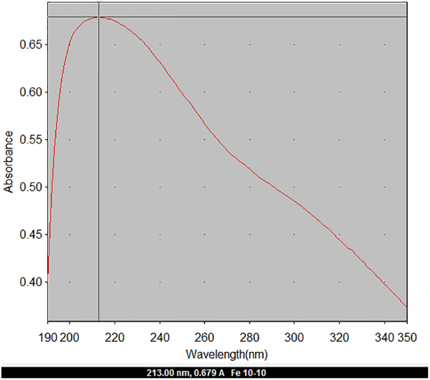
The absorption spectrum of water phase iron nanoparticle.

NIC (a) size distribution and (b) Zeta potential.

The absorption spectrum of water phase iron nanoparticles prepared by EDM for varying the preparation time.
The absorbance and wavelength of water phase iron nanoparticles prepared by EDM for varying the preparation time.

EDM: electrical discharge machining.
Conclusion
To seek ecologically friendly methods for preparing NIC, this study developed an automated EDM system with real-time monitoring. The system was based on ESDM and incorporated VisSim software, an Arduino microcontroller, an RT-DAC4/PCI card, and laser positioning technology. The EDM system developed in this study is advantageous for its small size. In addition, its production cost, approximately US$5300, is considerably lower than that of an industrial-grade EDM. The application of the EDM system developed in this study in the ESDM method to prepare nanometals would substantially reduce equipment costs. The results of this study are listed as follows:
The laser positioning technology and closed-loop motor control enable automatic alignment and precise positioning of the two discharge electrodes. Compared with manual alignment methods, this design achieves a higher alignment speed and superior precision. This design maintains the system in a ready state for NIC preparation and substantially increases process efficiency.
The VisSim software, Arduino microcontroller, and RT/DAC4 card enable real-time monitoring. The advantages of this monitoring function include a user-friendly interface, real-time status retrieval, and display of crucial parameters on a screen. Thus, onsite operators can instantly diagnose problems that may arise during the preparation of NIC and formulate response measures, thus improving the efficiency of preparation and the quality of the product.
This study employed the Z-N method as a replacement of the manual PID tuning method to adjust a PID controller in order to control the IEG. The results revealed that using the Z-N method to adjust the PID controller could achieve the reference command of Va (2.0 V) with a smaller overshoot in a shorter duration. Moreover, in a steady state, it could remain close to the reference command of Va with a small steady-state error. With its superior characteristics in terms of transient response and steady-state response, the Z-N method substantially improved the stability of discharge and increased the DSR from 22.25 to 28.99. These results confirmed that tuning the parameters of the PID controller through the Z-N method improved the efficiency and stability of the NIC preparation.
According to the UV-Vis and Zetasizer analyses, the NIC prepared in this study exhibited wavelengths of approximately 200–220 nm, zeta potential of approximately –11.6 mV, and diameters of approximately 155.0 nm. These data confirmed that this system can prepare NIC featuring excellent suspension stability.
The NICs prepared in this study contained only iron and oxygen; therefore, compared with NICs prepared using chemical methods, those prepared in this study were determined to be more suitable for medical use and to be safer for application in the human body.
Footnotes
Acknowledgements
The authors thank Dr Der-Chi Tien (Department of Electrical Engineering, National Taipei University of Technology, Taiwan) for his assistance and helpful discussions.
Handling Editor: Byung Sun Kim
Declaration of conflicting interests
The author(s) declared no potential conflicts of interest with respect to the research, authorship, and/or publication of this article.
Funding
The author(s) disclosed receipt of the following financial support for the research, authorship, and/or publication of this article: The authors would like to thank the Ministry of Science and Technology, Taiwan (NSC 103-2221-E-027-070) for financial supporting this research.