
Abstract
Turning by electrical discharge machining is an emerging area of research. Generally, wire-cut electrical discharge machining is used for turning because it is not concerned with electrode tooling cost. The process variant die-sinking electrical discharge machining can also be effectively used to generate free-form cylindrical geometries on difficult-to-cut materials with complex shapes at both macro and micro levels. The machining performance of electric discharge machine is defined and influenced by its process parameters, which significantly affects production rate and the quality of machined component. Thus, it is very important to select machining parameters and their levels cautiously in order to improve the outcome of the process. In this article, the authors have reviewed the research work carried out in the area of electrical discharge turning in the last decade for the improvement of material removal rate, surface integrity and roundness. In this review, various techniques reported by electrical discharge machining researchers on turning have been categorised in different electrical discharge machining variants. The article also discussed the future direction of research work in the same area.
Keywords
Introduction
Electrical discharge machining (EDM) has become one of the most extensively used thermoelectric non-conventional machining options which accounts for about 7% of all machine tool sales in the world. 1 It has been reported that aerospace-related industries own 40% of EDMs, general manufacturing about 16% and speciality jobs about 15%. 2 In recent years, EDM technique has been replacing drilling, milling, grinding and other traditional machining operations and is developing very rapidly. 3 It has been accepted worldwide as a standard process in the manufacture of forming tools. It is widely used for machining high strength and brittle materials to make dies, moulds and punches that are very challenging to machine by conventional machining processes. In addition, modern ED machinery is capable of finishing the parts for aerospace, automobile and surgical components.4,5 EDM provides a means of machining hardened steels, carbides, ceramics and any other material that offers 1 S/m of electrical conductivity. 6 The key advantage of EDM is that tool and workpiece do not come into contact, thus eliminating chatters and vibration problem and allowing small or thin components to be machined without mechanical force as well as minimum damage to work material.7,8 Today, an electrode as small as 0.1 mm can be used to drill holes into curved surface. 9
EDM was originally observed by English scientist Joseph Priestley in 1770. He noticed in his experiments the erosion of metals by electrical discharges. 10 It was only in 1943 at Moscow University where Russian physicist couple Dr B.R. Lazarenko and Dr N.I. Lazarenko exploited the destructive properties of electrical discharges for constructive use. 11 At nearly the same time, similar claims were made when three American employees – Harold Stark, Victor Harding and Jack Beaver – came up with a view of using electric discharge to remove broken drills and taps from costly parts used in aircraft applications. However, Lazarenko in Russia first introduced control machining by electrical spark in 1944. The first British patent was granted to Rudolf in 1950. Unites States, Japan and Switzerland developed their machines around 1950. After pioneering investigation by Lazarenko, the EDM process has attracted worldwide attention as a technique for metal machining. Then onwards, research and development have brought this process to its present level.12–14
This article provides a review of the various research activities carried out on electrical discharge turning (EDT) process during the last 15 years (2000–2014). The study is about turning operation using different EDM variants. The article is organised as follows: section ‘EDM principle’ briefly mentions mechanism of material removal in the process along with the process parameters. Different EDM variants along with their working and applications have been presented in section ‘EDM variants’. Section ‘EDT’ describes the comprehensive review of the process, and it is categorised into different EDM variants. This includes the academic research carried out on EDT in the field of material removal rate (MRR), methods of improving MRR, surface finish, methods of improving surface finish, roundness, and methods of improving roundness. Each category describes the activities carried out by the researchers and the development of the area that brings it to the current trends. The last section concludes this review study and outlines the future directions for EDT research.
EDM principle
The working principle of EDM is based on the thermoelectric energy. The basic scheme of EDM has been depicted in Figure 1. Basically, it uses electrical energy and turns it into thermal energy through a series of nonstationary and transient electrical discharges occurring between the tool electrode (normally cathode) and the workpiece (normally anode).15,16 Both tool and workpiece must be conductor and be immersed in dielectric liquid. Often hydrocarbon oil or kerosene is used as a dielectric medium. 17 These days non-hydrocarbon dielectrics (such as Elbolub, Vitol QL, Lonorex 500 plus and Oel-Held) are also commonly used in EDM industry. 1 The dielectric must have low viscosity, high dielectric strength, quick recovery and effective flushing ability. The workpiece and electrode are separated by a specific small gap (∼5–100 µm), so-called spark gap; usually certain gap is needed to avoid short circuit. 18 The electrical resistivity of both the electrodes must lie nearly 100–300 Ω cm to generate electrical discharge between the tool and workpiece.10,19–21
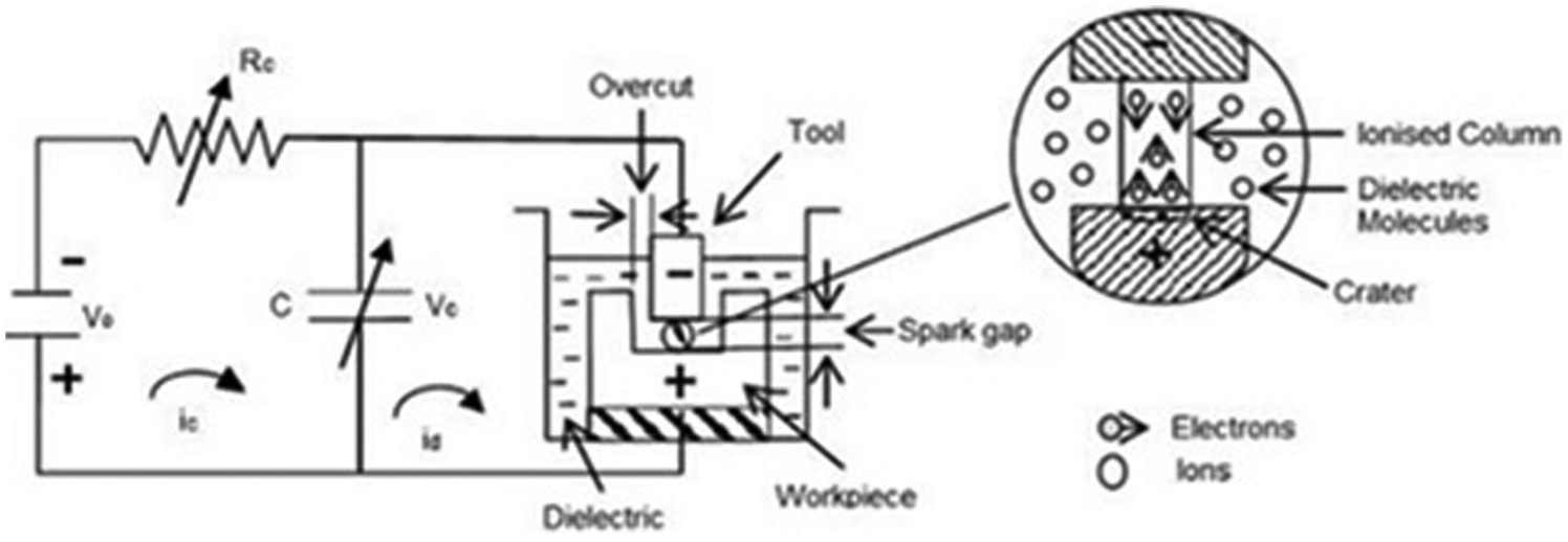
Basic principle of electrical discharge machining using relaxation circuit (single discharge condition).
When an appropriate voltage is developed, electrical breakdown of dielectric occurs and an electric discharge of short duration (∼0.1 to 3600 µs) is generated between the cathode and anode.6,22 The spark radius is usually very small (nearly 100–200 µm) since the breakdown (spark) occurs at a spot where the tool and workpiece surfaces are closest and the spot changes after each spark.23,24 Due to breakdown, voltage falls and current rises instantaneously; as a result, a plasma channel has been characterised that produces an immense amount of temperature.25,26 This higher temperature causes melting or even vaporisation of the workpiece surface. When the voltage supply is turned off, the plasma channel breaks down and allows dielectric fluid to implore the channel and flush the molten material 27 since the molten material is removed partially and the remaining will be resolidified (white layer/recast layer) at a very high rate. 10 As a result, tiny craters can be seen on the workpiece surface. The crater size can be controlled by discharge energy, which can be adjusted on machine by setting the discharge current.
Based on this principle, a number of EDM process variants are currently employed in industry, involving die sinking and wire cutting, together with more specialised formats such as electrical discharge drilling (EDD), electrical discharge grinding (EDG) and electrical discharge texturing (EDTx). These are the most favourable variants owing to their ability to machine exotic and high strength and temperature resistive (HSTR) materials with the scope of generating complex shapes and profiles.
Process parameters
EDM performance mostly depends on electrical parameters instead of non-electrical parameters and capacity of machine tool. However, sensitivity of the servo system and desired properties of the tool electrode material play a vital role that can affect machining performance. EDM process parameters can be divided into two categories, that is, electrical and non electrical. 28 Main electrical parameters are peak current, discharge voltage, pulse duration (pulse on-time Ton), pulse interval (pulse off-time Toff), polarity, electrode gap (spark gap) and pulse waveform. Non-electrical parameters include gap flushing, tool electrode rotation and workpiece rotation.
Peak current
It is considered as the most important electrical parameter measured in units of ampere. Usually, direct current is supplied to the circuit in the form of pulses using pulse generator. The pulsed current increases during each pulse on-time until it approaches a preset level and is termed as peak current. Generally, higher current is applied to improve MRR but at the cost of surface finish and tool wear. 29
Discharge voltage
In EDM, discharge voltage is related to spark gap and breakdown strength of dielectric fluid. Before current can flow, the voltage increases until ionisation path is created between the tool and work material. Once the current starts to flow, the voltage drops and is stabilised at the working gap level. The discharge voltage depends on the paired electrode material and machining conditions. 30
Pulse duration
Pulse duration is commonly expressed as Ton. It is the duration of time measured in units of microseconds. During this period, the current is allowed to pass through the tool electrode towards the work material, and all the work is done (metal removal) during Ton. With larger pulse on-time, more work material will be removed and the resulting crater will be broad and deeper than the crater produced by shorter pulse on-time.
Pulse interval
Pulse interval provides deionisation of liquid dielectric and stability to electric discharge pulse. This parameter affects machining speed and stability of cut. If Toff is too short, the material removed will not be flushed away as a result of which the dielectric will not be deionised. This will cause the next spark to be unstable. At the same time, Toff must be greater than deionisation time to prevent continued spark at one point. 31
Pulse waveform
Pulse waveform depends on the pulse generator, the machine equipped with. Pulse waveform is normally rectangular due to the rectangular pulse generator, but other wave shapes have also been developed with a generator (hybrid generator) which can produce trapezoidal wave forms and can give zero tool wear condition.28,32
Electrode gap
Electrode gap is set by tool servo mechanism. For maintaining the predetermined spark gap, a servo control unit is generally used. Sometimes, a stepper motor is used instead of the servo motors to respond well to the average gap voltage. The gap is sensed through the average voltage across it, and this voltage is compared with the preset value. The difference is used to control the servo tool mechanism. 33
Polarity
The polarity of the electrode can be either positive or negative. It depends on tool material, work material, current density and pulse on-time. Electrode polarity is usually positive to obtain more MRR and less tool wear rate (TWR).23,30 Modern power suppliers insert an opposite polarity ‘swing pulse’ at fixed interval to prevent arcing. A typical ratio is one swing pulse for every 15 standard pulses. 28
Gap flushing
To maintain stable machining condition, liquid dielectric is flushed through the electrode gap to remove the debris particles during machining. The type of dielectric, flushing pressure and method of flushing affect the MRR and TWR.15,34 Insufficient flushing of debris particles results in the deterioration of machining accuracy. The basic characteristics required for dielectric in EDM is high dielectric strength and quick recovery after each breakdown.
Workpiece and tool rotation
Workpiece rotation improves the circulation of dielectric fluid and temperature distribution over the work surface. This is due to the generation of centrifugal force that causes more debris particle to be removed from the machining zone and cool the work material at higher rate. 35 This improves MRR and Ra as well. In the same mode, electrode rotary motion improves the gap flushing and machining efficiency.36,37
EDM variants
Die-sinking EDM
The die-sinking EDM process is extensively used for producing complex shapes in die and mould cavities in high-strength materials. It seems most promising and only an alternative for machining hard metals and alloys.38,39 Its main applications are in forging dies, pressure casting die, injection moulding, press tools and powder metallurgy.40–42 During the die-sinking process, a preshaped tool electrode is mirrored on the workpiece as shown in Figure 1. Fabrication of geometrically complex EDM electrode is very difficult to produce and is time-consuming too. It can account for about 50% of the total process cost. Consequently, the cost of EDM tooling is increased.43,44 The commonly used electrode materials are copper, copper–tungsten, brass, graphite and so on. Nowadays, computer numerical control (CNC) machining technology and rapid prototyping techniques are used to manufacture EDM electrode. 45
Wire-cut electrical discharge machining
Wire-cut electrical discharge machining (WEDM) is a most popular variant of conventional EDM process, also called travelling WEDM. The material removal procedure of die sinking and WEDM is similar since WEDM uses a continuously travelling thin wire electrode instead of preshaped EDM tool. 46 Usually, EDM wire is made of copper, brass or tungsten with a diameter range of 0.05–0.3 mm. Thus, tooling cost is eliminated. The material is removed by a series of discrete spark between cathodic wire electrode and anodic workpiece.47–50 The wire is used only once since wire loses its form after being passed once through the workpiece. WEDM is suitable for machining of complex shapes which have very small corner radii, sharp edges and capable of machining precise cylindrical forms. The process can be used for both machining and cutting. It is commonly used for the manufacture of stamping and extrusion tools and dies, grinding wheel form tools and so on and has applications in aircraft and medical parts.51,52
EDG
EDG can be utilised as a third EDM variant. EDG is a hybrid process, which integrates mechanical grinding and EDM. 53 It is a most popular method used for micro-manufacturing of micro-tools and micro-parts (micro-shafts, electron emitter, ejector pins, etc.). The material removal mechanism is the same as that of EDM. 54 Both sinker EDM and WEDM can be used for EDG. However, wire electrical discharge grinding (WEDG) becomes the most powerful, flexible and extensively used method of EDG. 55 Sinker EDG uses a conductive rotating grinding wheel (of graphite, diamond etc.) as tool, whereas WEDG uses a continuously feed travelling wire as tool electrode.56,57 With WEDG, it is only possible to manufacture very small convex shape micro-parts having diameter less than 20 µm.58,59
EDD
EDD is basically an EDM process. 60 ED drilling is a well-known process for producing deep micro-holes in electrically conductive materials, whether the material is hard or soft. 61 It is also known as micro-electric discharge drilling (µEDD) process. The term µEDD is used because conventional die-sinking EDM can also be used for drilling holes. However, it is much slower than ED machines specifically designed for micro-hole drilling. 62 The µEDD is the main process that is applied to producing micro-holes in diesel fuel injectors, turbine blade, drug delivery orifice, ink jet printer nozzles and so on.61,63 The µEDD is accepted as an efficient method for the fabrication of precise micro-straight hole in the minimum machining capability diameter down to 5 µm. 64 In diesel fuel injection components, hole diameters can be less than 200 µm. Usually, tungsten, cemented carbide, tungsten–copper, copper and brass are used as electrode materials.
EDTx
EDTx process works on the same principle as EDM. Actually, EDM has more recently evolved into EDTx process. It is also referred to as electroblast or electro-erosion texturing.65,66 It is a specialised texturing process that provides superior surface texture on cold rolls having broad diameters and lengths, used in auto industry for body panels and for other pressed steel products. 67 The texture (surface roughness) ranges from Ra 0.5 to 10 µm and can be easily achieved despite roll hardness. It is a fast and reliable process of providing surface textures on cold mill rolls with a good combination of quality and performance.68,69
EDM milling
The historical starting point of EDM is somehow in between die-sinking EDM and WEDM. EDM is a machining process where a cylindrical tool electrode follows a predetermined programmed path in the same way as the cutting tool does in CNC milling. The EDM tool is a tubular copper electrode rotating at high speed in the dielectric oil, and the material is removed layer by layer by sparking. 70 EDM produces pocket shape on the workpiece using a simple electrode. It is similar to WEDM cutting as tubular electrodes are standard consumable parts and wear is compensated by the renewable electrode; thus, preparation time for EDM is dramatically reduced. 71 Milling and turning by spark erosion are an emerging branch of EDM. Both the machining processes are different in the same way as traditional turning and milling; however, the working principle of EDT and EDM remains the same.
EDT
Several researchers have contributed to the development of EDT process. One application of the die-sinking EDM machine is in turning aerospace honey-comb seals where internal and external seals are machined to a burr-free finish with internal or external diameters from 300 to 1400 mm. 72 A claim of this application includes a 50% improvement in production time over other ED machines. The EDT process is broadly applied to manufacture cylindrical components of hard and fragile materials. The initial shape of the work part need not be cylindrical. Figure 2(a)–(c) shows the concept of EDT process using different EDM variants. The idea of utilising WEDM to machine cylindrical parts has been reported by Dr Masuzawa’s research group to manufacture small-diameter pins and shafts of diameter 5 µm. 54 Manufacturing of macro-level automobile component like diesel injector plunger is also possible with WEDM. 73 The process is found to have many advantages over the conventional turning process, such as good repeatability, burr-free machining, and elimination of vibration and stresses due to non-contact machining process.
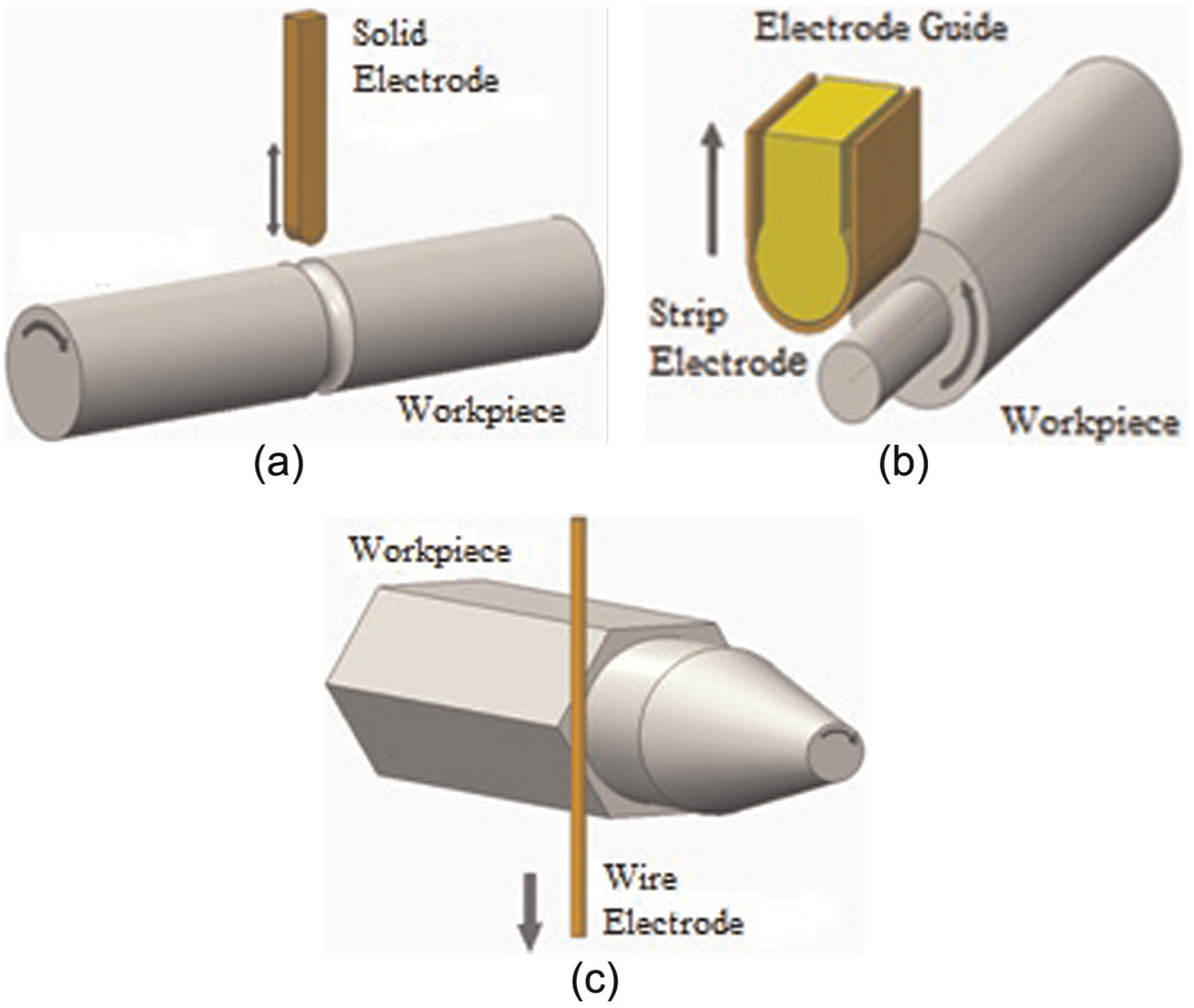
Electric discharge turning using different EDM variants: (a) die sinking EDM turning, (b) strip EDM turning and (c) wire EDM turning.
Research in WEDM turning
Qu et al.74,75 worked on the development of cylindrical wire electrical discharge machining (CWEDM) process to fabricate cylindrical parts of high-strength materials. The experiment was conducted in two phases; in the first phase an additional rotary spindle (axis) is added to generate cylindrical geometries. Spindle error can influence MRR, surface roughness (Ra) and roundness of the part. In the second phase, a mathematical model was derived for MRR. Two experiments were designed and conducted to find maximum MRR on brass and carbide material. Based on the obtained findings they conclude that maximum MRR for CWEDM was higher than that in two-dimensional (2D) WEDM for same machining condition and work material.
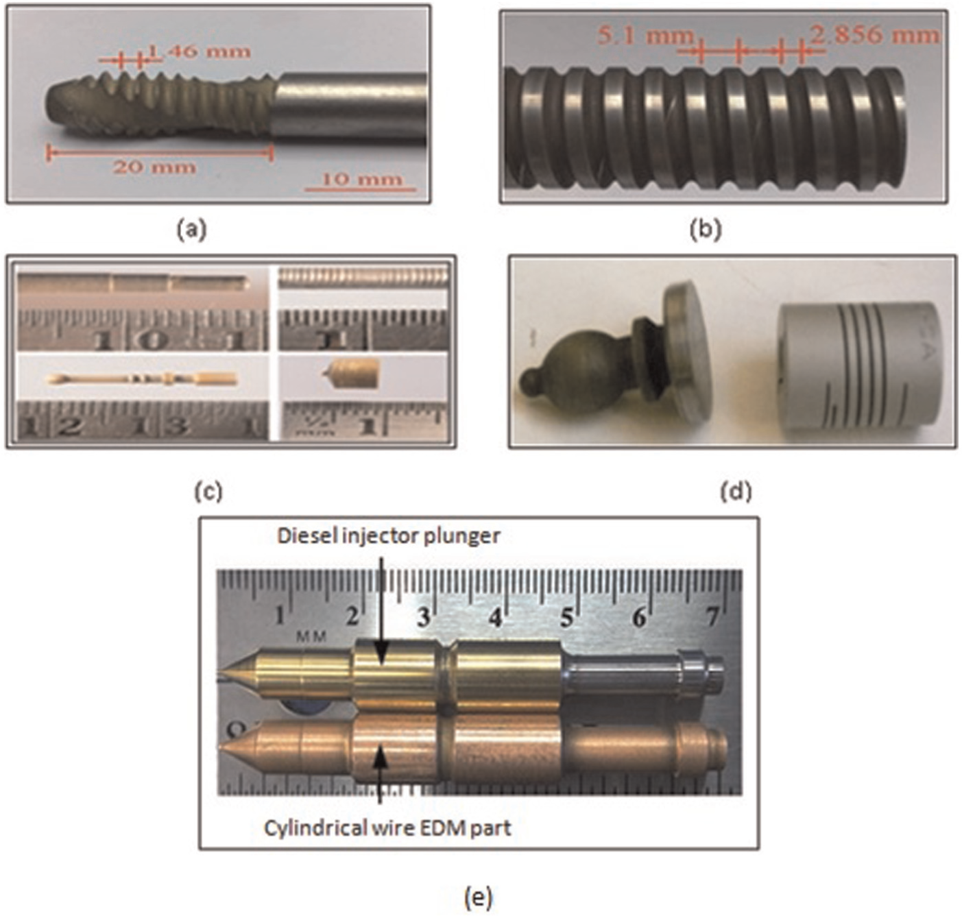
The same authors further extend their experimental study to investigate surface integrity and roundness of the part, produced by the CWEDM process. 76 Two machining parameters, that is, shorter pulse on-time and lower feed rate, were to be found most important, and their influence on surface roughness and roundness was investigated. A mathematical model was established for surface integrity and roundness, and good estimate for the surface finish and roundness of CWEDM parts was found. Authors have also created a CWEDM part with the same shape as the diesel engine fuel injector plunger shown in Figure 3(e).
Mohammadi et al.80,81 investigated the effect of machining parameters on surface finish and roundness in wire electrical discharge turning (WEDT) of cemented steel. A new rotational axis is utilised in order to manufacture axisymmetrical forms. Experimental results show that power is directly proportional to surface roughness, that is, by increasing power surface roughness increases significantly. Other parameters have least effect on Ra. In addition, none of the parameters influence the roundness considerably. The effect of power, wire speed and servo on roundness is more significant than time-off, voltage, wire tension and rotational speed. Based on the findings, a mathematical model was derived using regression analysis. Confirmation results validate the use of the Taguchi method for improving machining performance and optimising the machining parameters.
Haddad and colleagues82–84 performed an experimental investigation of cylindrical wire electrical discharge turning (CWEDT) process on AISI D3 tool steel. The paper finds the influence of process parameters, namely, voltage, power, pulse off-time and spindle rotation on MRR, Ra and roundness. Experimental findings indicate that voltage and power are in direct proportion to MRR, whereas pulse off-time and spindle rotation show reverse effect on it. Furthermore, the value of Ra tends to increase as voltage and power factor increase, but at higher voltage rate its increase is less. Moreover, spindle speed and pulse off-time were found to be the most influencing factor over roundness, that is, value of roundness decreases when these two increase, while voltage and power show reverse effect on it, that is, increasing roundness.
The next experimental study was conducted by the same author in the year 2007. 85 The objective of the study was to investigate the effect of design factors on MRR in CWEDT. Response surface methodology (RSM) were utilised to investigate the process parameters, namely, voltage, power, pulse off-time and rotational speed. The results of investigation show that power and voltage have direct effect on MRR; as these increase, the value of MRR also increases. Also, pulse off-time shows reciprocal and spindle rotational speed represents little effect on it. Based on the findings, it was observed that for maximum MRR the process parameters, namely, voltage and power should be fixed as high as possible and other parameters should be fixed as low as possible.
Mohammadi et al. 77 in the same year worked on the optimisation of MRR using statistical analysis in WEDT. The effect of multiple parameters, namely, power, voltage, time-off, wire speed, wire tension, rotational speed and servo on MRR was investigated. Signal-to-noise (S/N) ratio analysis was employed to obtain optimal condition. Figure 3(d) exhibits the cylindrical WEDT part produced by the author. From the experimental analysis, it is evident that power and voltage have the most significant effect on MRR, that is, it shows increasing trend with an increase in these parameters. It was also noticed that servo and rotational speed are reciprocally proportional to MRR, and wire tension has very little effect on it.
Mohammadi et al. 86 carried out an experimental investigation of Ra in CWEDT of AISI D3 tool steel. In experimental design, new machining parameter form factor (cone angle) along with power, voltage, pulse off-time and rotational speed has been introduced to study its influence over Ra. Investigation results demonstrate that voltage, power, time-off and spindle speed are the most effective parameters on Ra. However, power is the most significant parameter than other factors. As the value of power and voltage increases and spindle speed and time-off decreases, Ra increases. Moreover, cone angle does not affect the Ra. It is also found that the magnitude of Ra and thickness of recast layer are proportionally related.
Janardhan and Samuel73,87 used pulse discrimination algorithm to analyse the effect of machining parameters on MRR, Ra and roundness. Pulse train data were collected using pulse train data acquisition system and pulse discrimination algorithm, respectively. Machining parameters pulse off-time, spindle rotation speed, spark gap, servo and flushing pressure are varied to study their effect with respect to pulse train in WEDT. According to their reports, MRR increases nearly 50% by decreasing pulse off-time and spark gap, whereas servo feed and rotational speed show direct proportion to MRR. Furthermore, by reducing pulse off-time and spark gap, Ra improves nearly 56%, while servo feed shows direct proportion to Ra. Moreover, roundness error reduces 74% by reducing pulse off-time and spark gap and by increasing rotational speed and flushing pressure. A miniature part machined with WEDT is shown in Figure 3(c).
Gjeldum et al. 88 formulated the polynomial mathematical model to determine the influence of design parameters pulse current, pulse pause duration and rotation speed on MRR. Experimentation was performed on X5CrNi18-10 steel by using three-level full factorial design and feed-forward back-propagation neural network model. Based on the performed analysis, pulse current parameter had a big influence on MRR and shows increasing trend, that is, by increasing pulse current MRR increases significantly. Material removal increases with a decrease in pulse pause duration while spindle speed has small impact on MRR. They presented a comparison of two different mathematical modelling techniques for the prediction of MRR. Their findings show better interpolation capability using artificial neural network (ANN) programming over design of experiment and regression analysis.
In the same year, Mohammadi et al. 89 studied the machining of cemented steel in WEDT process using multi-response signal-to-noise (MRSN) ratio method. Influence of process parameters was evaluated over MRR, Ra and roundness. The study was conducted in two steps: higher priority was given to MRR followed by Ra and roundness in step 1, and in step 2, higher priority was given to Ra followed by MRR and roundness, respectively. The experimental results confirm that as MRR increases, Ra decreases and roundness also decreases by more than one time in steps 1 and 2, respectively. These results confirm the effectiveness of the Taguchi approach and MRSN for experimental design and multi-response optimisation, respectively.
Weingärtner et al.90,91 presented a WEDM investigation on high-speed rotating workpiece of brass (CuZn39Pb3). An electro-thermal model was developed to examine the effect of relative speed on eroded craters. It was found that the plasma arc column easily slides over the anode during high speed. As a result, crater extends (erodes) along the relative speed direction and reduces slightly perpendicular to it. Therefore, the volume of eroded craters increases as relative speed is increased, indicating that higher melting efficiencies can be achieved when high relative speeds are applied.
Krishnan and Samuel 92 optimised MRR and Ra using multi-objective optimisation method based on non-dominated sorting genetic algorithm (NSGA-II) in WEDT. The process was modelled using ANN and adaptive neuro-fuzzy interface system (ANFIS). An external rotary axis was developed so that AISI D3 workpiece can be turned on WEDM. All the experiments were planned according to Taguchi fractional factorial design with varying process parameters. The experimental data show that there is an improvement of 28% on MRR for desired Ra 2.05 µm. However, the response of ANN model can be further improved with large experimental data.
Dhake and Samuel 93 presented a study on the application of WEDM for machining axisymmetric contour and helical profiles on cylindrical brass workpiece. They studied the dimensional accuracy of cylindrical components obtained by machining with WEDM. To carry out cylindrical turning, authors develop a precision rotary set-up and motorised linear set-up (for linear motion) in order to manufacture axisymmetric parts. Experimental results show that the maximum and minimum deviation (percentage error) of the part after machining from design specification for axisymmetric forms was found to be 3.10% and 0.10%, respectively. The average pitch value and standard deviation for helical form were found to be 0.031 and 0.028 mm, respectively, using optical microscope. From the findings, it can be concluded that CWEDM has the capability to establish itself as a critical technological process for machining a wide range of forms and profiles.
Rajkumar et al. 94 worked on the machining of Al/SiCp metal matrix composite in WEDT process. RSM using the Behnken method was employed to study the influence of input machining parameters, namely, pulse on-time (Ton), gap voltage (V) and spindle speed (SS) over MRR. Regression equation was derived for MRR for easier prediction. The results of the investigation show that high pulse on-time, medium gap voltage and lower spindle speed lead to higher MRR and effective machining.
Giridharan and Samuel 95 studied the impact of process parameters (pulse off-time, servo feed and spindle rotation) on energy consumption, Ra and MRR throughout WEDT of EN 24 (AISI 4340). The energy was calculated using power pulse train by linking power pulse with respect to time. According to their findings, energy consumption decreases by increasing pulse off-time for constant spindle rotation and servo feed. It is also found that the surface finish improves up to nearly 55% by increasing spindle rotation and keeping servo feed and pulse off-time constant. Moreover, MRR shows inverse relation with servo feed and is found to be high at lower level. Furthermore, MRR increases nearly 50% at varying spindle speeds, keeping all other parameters constant.
Gjeldum et al. 96 investigated the influence of process parameter and work material dimensions on MRR. They proposed a mathematical model to predict maximum achievable MRR by employing Broyden–Fletcher–Goldfarb–Shanno (BFGS) back-propagation algorithm based on ANN. Maximum pulse current, pulse pause time, spindle rotation, length of discharge area and cutting radius were used as a input machining parameters during CWEDT of X5CrNi18-10 steel. Results of study exhibit that among the process parameters maximum pulse current has significant impact on MRR; as it increases, MRR increases as well. MRR also increases with an increase in maximum pulse current and discharge area length. However, spindle rotation (up to 1000 r/min) has a little effect on MRR.
Yan and Hsieh78,79 proposed a new pulse discrimination system for process monitoring of WEDT. The pulse discrimination system can identify four major gap states (open circuit, normal spark, arc discharge and short circuit) and compute sparking frequency and average delay time based on the characteristics of gap voltage waveform. Authors created a threaded WEDT part which is shown in Figure 3(a) and (b). Their study shows that in CWEDT the rotary spindle moves independently with the translation axis (asynchronous motion), which means that table feed rates for the translation axis were adjusted by servo feed control to keep forward sparking gap in the wire transverse direction at a proper width. The rotary motion with a fixed speed changes lateral gap during the CWEDT process. And therefore conventional gap voltage control system could not react properly and even failed to respond to the variation of lateral gap width during CWEDT by only controlling the table feed rate. On the other hand, it has been observed that WEDT exhibits more stable machining condition than CWEDT. This is due to the open architecture CNC system which can provide synchronous motion control between rotary axis and translational axis, and therefore, servo feed control could respond to change in spark gap condition by adjusting translational axis feed rate and rotary axis simultaneously. Thus, pulse discrimination system can provide more clear information than average voltage for online evaluation of spark gap condition throughout the WEDT process.
Turning by WEDM has given new research domain to the researchers. It can be inferred from the above section that the researchers have performed experimental as well as theoretical investigations and found that the WEDM is suitable for turning to produce helical profiles and free-form axisymmetrical geometries on exotic and high-strength materials. The process eliminates the need for preshaped electrode which is generally required in die-sinking EDM. Number of researchers from Japan, China, Korea, India and Iran worked in this area and gave major contribution for progressing research. The process has the potential to fabricate cylindrical and complex shapes which have sharp edges and small corner radii with high precision. In EDM, turning wire electrode leaves cusps on machined surface because of its small diameters and wire breakage 76 which greatly affects the surface finish of the machined part. Moreover, one of the limitations of the process is low machining speed as compared to constituent processes. However, authors believe that machining speed and material removal can be increased by increasing workpiece rotations. Simultaneously, roundness error can also be minimised. 77 No significant work has been found on turning at high rotational speed of the workpiece. The available literature shows that very few work materials were used so far since there is not much research work found on advanced engineering materials in this area. However, the applications of these materials are growing rapidly in aerospace industry due to its light weight, high strength and good wear resistance. WEDM is a cost-effective machine tool that shows higher capability for machining these materials with good accuracy and precision.
Research in strip EDM
Song et al. 97 developed a novel strip EDM method that uses a thin strip electrode. The strip width and thickness were 10 and 0.1 mm, respectively; was made of brass; and performed the same function as wire in WEDM; thus, electrode wear is not concerned in strip EDM. Stainless steel-304 was utilised as the work material. The experimental findings indicate that in strip EDM, turning MRR was found to be nearly two times higher and Ra was five times smoother than WEDM turning.
The same authors reported that strip EDM can be utilised for milling process and proposed it as a substitute for general EDM. 98 This experimental work was more or less similar to the previous work done, although it was different in some aspect, namely, tool material and machining type. Their experimental results revealed that MRR and Ra of general EDM were found to be lower by 61.35% and 8.5 times higher (rougher), respectively, than that obtained via strip EDM. They also reported that copper electrode leaves copper on the machined surface. When compared to the copper tool, brass electrode did not discolour the surface and produces stable machining condition.
By the same authors, another research study was conducted on turning by the strip EDM process.99,100 They carried out a comparative study on WEDM turning and strip EDM turning using brass electrode under same machining conditions. Experimental results show that MRR of strip EDM was found to be 74.3% higher than the MRR of WEDM since WEDM turning produces cusps on machined surface and are responsible for less MRR due to its small machining area, whereas in strip EDM turning machined surface was found to be 4.6 times smoother due to large machining area and non-breaking electrode. Figure 4 shows the part produced using strip EDM.
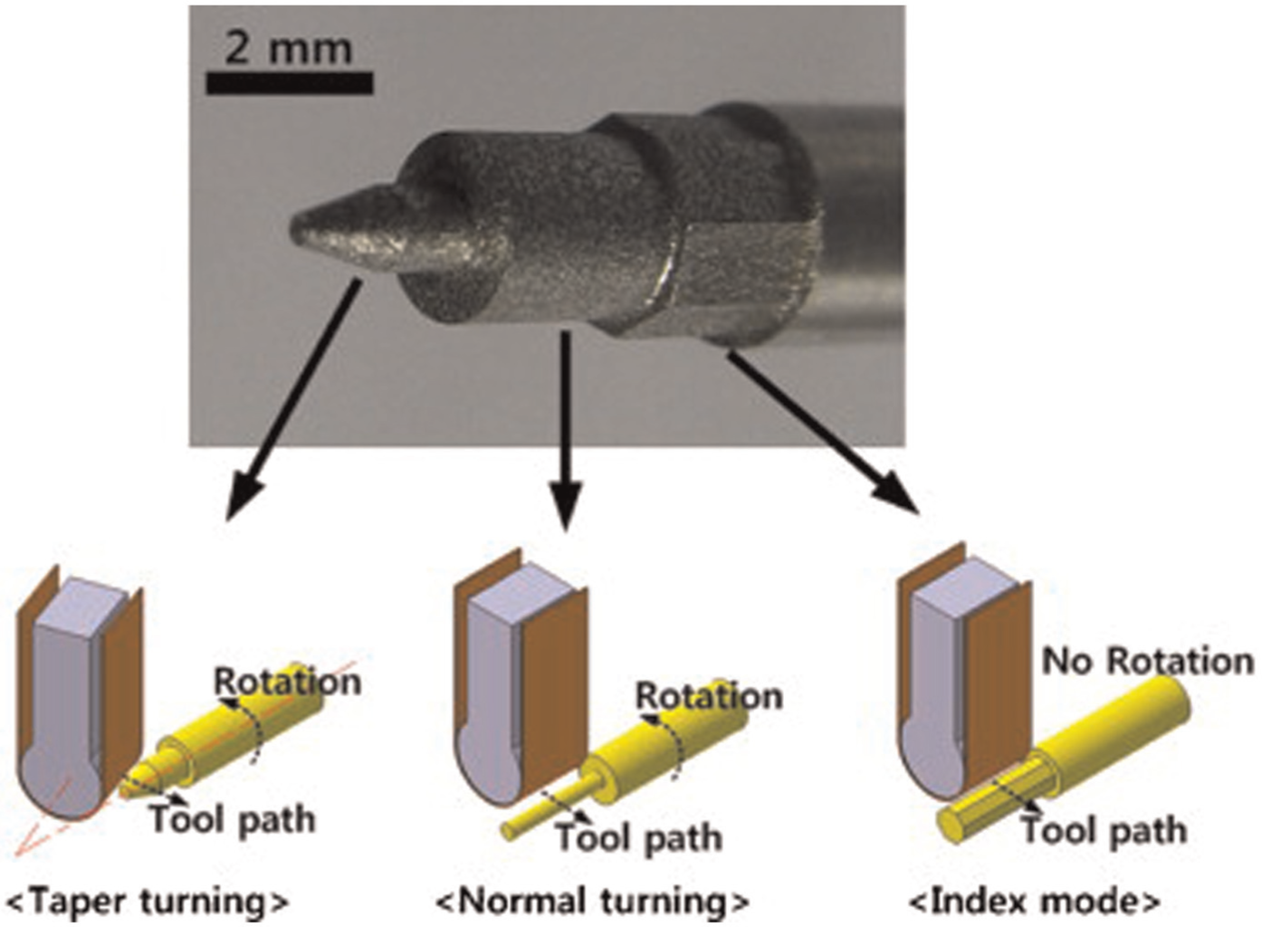
Product created using three kinds of strip EDM turning. 99
This novel method was developed from the researchers of Korea. The method is capable of EDM turning, milling and grooving operations. It provides higher MRR and produces cusps-free machined surface as compared to WEDM. Strip EDM not only overcomes the cusps problem during machining but also helps to achieve higher machining speed, higher material removal, surface finish and roundness at very low rotation speed (0.6 r/min). This is possibly due to the large machining area of electrode. The literature shows that only normal turning and taper turning work has been attempted so far; however, no research work has been found on free-form profile turning in the context of strip EDM. The researchers have improved various quality characteristics by introducing strip kind of tool electrode, and it emerged as an efficient process for machining any conductive material irrespective of its hardness and strength. In addition, there is no tooling cost in strip EDM as it uses a conductive strip as tool. The strip EDM has given new hope for manufacturing industries to overcome the limitations of WEDM with respect to MRR and Ra up to a certain extent. Since the methodology is new, very few published research publications are found in this domain.
Research in sinker EDM
Guu and Hocheng 35 studied the influence of workpiece rotation during EDM of AISI D2 tool steel using copper electrode. The after-effects were compared with conventional EDM without workpiece rotation under the same machining conditions. Experimental findings indicate that centrifugal force due to workpiece rotation enhances dielectric flow and improves gap flushing; thus, MRR increases up to two times that of conventional EDM at the same pulse on-time. Furthermore, surface finish improves with increase in workpiece rotational speed (up to 5000 r/min). On the other hand, in conventional EDM, eroded chips filled in machining gap hinder sound discharges, produce unstable machining condition and lead to poor surface quality.
Uhlmann et al. 101 conducted a comparative experimental study of EDT, EDG and WEDG to analyse the machining effect that resulted from the high rotational speed of the electrodes. On one hand, they were considered workpiece rotational speed in EDT and WEDG. Cold working steel 90MnCrV8 and W-Cu75/25 were used as workpiece and tool material, respectively. On other hand, they were considered peripheral speed of both the electrodes in EDG. The experimental results make clear that in regard to EDT and WEDG, MRR grows with higher circumferential speed and discharge energy, but it causes increase in roughness of machined surface. Subsequently, the author expects that there is a relation between Ra and flow speed of dielectric due to synchronous rotation of electrodes in EDG, and this requires further experimentation and analysis.
Matoorian et al. 102 established optimum process condition for EDT using the Taguchi method. In their investigation, an L18 orthogonal array, based on the Taguchi design method was adopted to study the effect of process parameter, namely, power, voltage, pulse on-time, rotational speed and servo upon MRR while machining HSS-1.3255. The experimental results show that power and rotational speed have significant effect on MRR and are directly proportional to it. However, pulse on-time and servo have significant and reciprocal effect on it. The other parameters are found to be less significant. Figure 5 shows the EDM machined specimen.
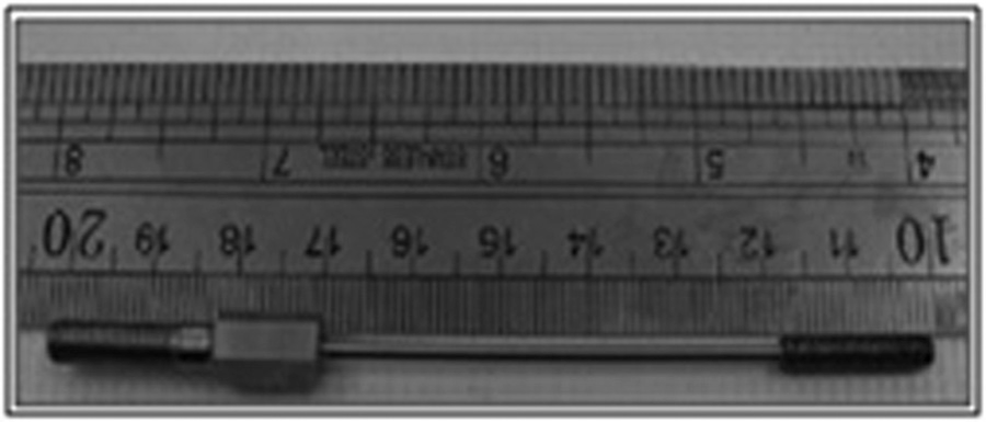
A cylindrical electrical discharge turned part. 102
The effect of adding rotary motion to the workpiece was studied, and many researchers have shown that it improves MRR and surface finish to a great extent. MRR obtained due to workpiece rotation was nearly twice that of conventional EDM. 35 Due to the work rotary motion, distribution of temperature is more uniform than the conventional EDM, and associated residual stresses are less detrimental. At high spindle speed, micro-voids did not exist and better surface finish can be obtained. Thus, the process seems active and time saving. This is possibly due to larger machining area of the tool electrode and rotary motion of workpiece. However, lesser amount of work has been found on EDT operation in context of die-sinking EDM. Hence, die-sinking EDM can come out as a potential candidate for EDT of exotic materials.
Research in hybrid EDM
Mohammadi et al. 103 introduced ultrasonic vibration (UV) into WEDT to investigate its effect on machining of HSS. A rotary axis is attached to produce axisymmetrical parts. Four design parameters were selected, that is, UV, power, spindle speed and pulse off-time, to study its effect on MRR. Based on the experimental findings, UV and power were found as the most significant factors, that is, by increasing power and UV, MRR increases significantly. In addition, pulse off-time and spindle speed have a major effect on MRR; however, pulse off-time shows reciprocal effect on it.
The same authors combine UV with WEDT to examine its effect on MRR and Ra. 104 Statistical analysis technique was selected to evaluate the influence of input machining parameters, that is, UV, power, pulse off-time and spindle rotational speed, and to obtain optimal setting of machining parameters. The results of the investigation show that in rough machining (using high power) of HSS UV effect is more significant than finishing condition with regard to MRR. Subsequently, Ra shows an increasing trend with increase in power. However, lower surface roughness can be achieved by maintaining higher value of time-off and workpiece rotational speed.
Mohammadi et al. 105 investigated the influence of UV on the size of eroded craters, Ra and sub-surface (recast layer and micro-crack) during machining of HSS cylindrical workpiece. They pointed out that the length of the crater is reduced by making use of UV due to an increase in the width and depth of crater under single discharge condition. Furthermore, the amount of material removed under higher rotation speed increases possibly due to the dispersion of more molten material out of crater, resulting in the reduction in thickness of recast layer and propagation of micro-cracks by applying ultrasonic vibration as depicted in Figure 6. The study also shows that high level of rotational speed and time-off and lower level of power are responsible for lower Ra along with higher MRR.
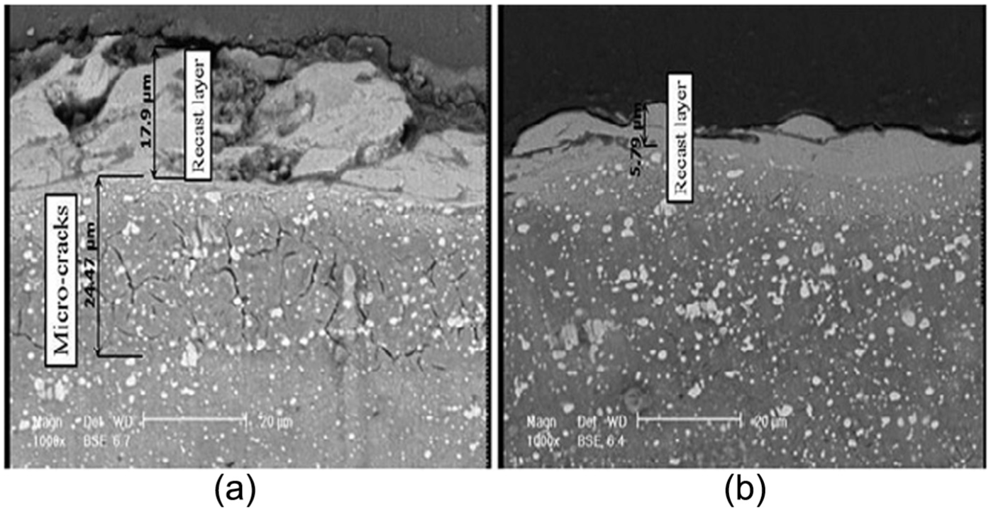
SEM micrograph of the workpiece cross section: (a) WEDT and (b) USWEDT.
That UV-assisted EDM is suitable for turning process was observed in mid-1980s. 25 UV mainly improves in dielectric circulation which facilitates fast removal of debris particles from electrode gap. High-frequency vibration of wire improves the discharge concentration and reduces the probability of rupture wire. This results in higher MRR and less recast layer on the workpiece surface. Particularly, the technique is effective in obtaining a high MRR in rough machining conditions. This method is recently employed in EDT process.
Conclusion
EDM has resulted as a cost-effective and precision machining option. The capability of machining complicated shapes and difficult-to-machine materials has made EDM one of the most popular non-contact machining processes. Turning by EDM is a novel application of this process that has added a new research domain to this technology. After an elaborate scrutiny of the published research, main conclusions can be summarised as follows:
It may be noted that most of the available research works on turning have been carried out by WEDM only.
As evident from literatures, no dominating work has been reported on turning by die-sinking EDM and UV-assisted EDM. So, this area is still open for future research.
Only few tool steels have been used so far as work material, and research work on many important superalloys and work parts produced by powder metallurgy are missing in the available literature. It has also been observed that very limited literature works are available on turning of metal matrix composite and ceramic material. So, there is a vast scope for machining of these advanced materials.
There is negligible published work available on the study of residual stresses, surface crack formation, workpiece surface modification, and condition monitoring and control of the process.
Most of the research works have been carried out on optimisation of process parameter for improvement of MRR and Ra. Limited work has been found on optimisation of process parameters using non-conventional technique such as genetic algorithm, fuzzy logic and neural networks.
Footnotes
Declaration of conflicting interests
The authors declare that there is no conflict of interest.
Funding
This research received no specific grant from any funding agency in the public, commercial or not-for-profit sectors.