
Abstract
This article presents the use of the rotary ultrasonic machining process for drilling holes in Ti6Al4V alloy which is regarded as a difficult-to-cut material due to its high-temperature strength and low thermal conductivity. This research presents an experimental investigation on the effect of the key rotary ultrasonic machining input parameters including ultrasonic power, spindle speed, feed rate, and the tool diameter on the main output responses including cutting force, hole cylindricity and overcut errors, and tool wear. No previous reports were found in literature to experimentally investigate the effect of the rotary ultrasonic machining parameters and the tool diameter on tool wear, surface integrity, and the accuracy of the drilled holes in Ti6Al4V alloy. The results showed that the rotary ultrasonic machining input parameters within the current ranges can significantly affect the quality of the drilled holes. Through proper selection of input parameters, holes could be drilled in Ti6Al4V alloy with smoothed surface morphology, low tool wear (0.7 mg) and very low cylindricity (2 µm) and overcut (120 µm) errors. Moreover, it was found that the selected level of any input parameter has the ability to significantly affect the influence of the other input parameters on the output responses.
Keywords
Introduction
Titanium and its alloys are important functional materials and are extensively used in many high-end applications including medical implants, aircraft, and turbine components. 1 This is due to their distinctive properties such as high strength-to-weight ratio, stability and corrosion resistance at elevated temperatures, high creep and fatigue strength, and biocompatibility.2,3 However, due to high strength, titanium and its alloys are regarded as difficult-to-cut materials. 4 Moreover, due to low thermal conductivity and high tool wear, titanium and its alloys are usually machined at lower cutting speeds and feed rates which results in longer machining times and incurs high cost with traditional machining (turning, milling, and drilling).1,5,6 Furthermore, titanium alloys present chemical affinity to most commonly used tool materials which results in weld formation4,7 that leads to poor surface finish and dimensional accuracy. Non-conventional machining processes such as electric discharge machining (EDM) and laser machining also have their limitations while machining titanium alloys in terms of generating heat-affected zones (e.g. recast layers), micro cracks, high surface roughness, and poor surface accuracy (e.g. kerf taperness).8–11 Therefore, it is crucially essential to investigate new manufacturing processes that could assist machining of titanium and its alloys in a more effective manner to extend and enhance their utilization.
When compared to conventional/non-conventional machining methods (e.g. drilling, grinding, EDM), rotary ultrasonic machining (RUM) is an alternative machining method which is of particular interest for the machining of hard and nonconductive materials. The particular advantages of RUM include lower cutting forces and temperatures, superior surface finish, and high machining accuracy.12,13 RUM is a hybrid machining process based on the combined material removal mechanisms of diamond grinding and ultrasonic machining resulting in higher material removal rates. 14 During RUM, the material is removed due to three main mechanisms: (1) the hammering action of the bonded diamond abrasive particles, (2) the abrasion action of the diamond particles due to rotation of the tool, and (3) the combination of the hammering and the abrasion actions. 15 The ultrasonically vibrating metal-bonded diamond abrasive tool is axially fed into the workpiece at a constant feed rate. The tools used in RUM are through coolant to keep the tool cool and sweep away the debris during machining.
RUM has been successfully applied to grinding and drilling of various types of hard and difficult-to-cut materials, such as composite materials, ceramics, and glasses.16–18 In these studies, the effects of RUM input parameters such as ultrasonic power (UP) and frequency, spindle speed (SS), F, and coolant types on output responses including cutting force, tool wear, surface roughness, and material removal rate have been considered. These studies have demonstrated the benefits of RUM in terms of low cutting forces and temperatures, superior surface finish, and high precision compared to the available alternatives (e.g. conventional grinding, milling).
RUM has also been used for drilling holes in Ti6Al4V alloy. Churi et al. 19 conducted a study on the feasibility of machining Ti6Al4V using RUM. It was reported that the surface roughness and cutting force decreased when compared to diamond drilling process without ultrasonic vibrations and the tool wear is reduced up to 85%. Churi et al. 20 reported an experimental investigation on the effects of tool variables (e.g. grit size and concentration) on cutting force, surface roughness, and tool wear. It was demonstrated that tools with higher diamond abrasive size resulted in generating higher cutting force and roughness and lower tool wear as compared to tools with smaller grit size. It was also illustrated that higher diamond concentration in tool resulted in lower cutting forces but exhibited higher tool wear and roughness when compared with tools with lower diamond concentration. Another research 21 studied the effects of SS, feed rate, and UP on cutting force, surface roughness, and material removal rate while drilling holes in Ti6Al4V. A study was also reported to use ultrasonic-assisted conventional tungsten carbide drilling of Ti6Al4V, and a reduction of up to 20% in feed force was demonstrated when using ultrasonic vibrations. 3 In addition, some studies were reported regarding using ultrasonic machining (only vibrating tool) to drill holes in Ti6Al4V and optimizing the process parameters for minimizing the surface roughness 8 and minimizing both the tool wear and the surface roughness. 22
It can be seen from the reviewed literature that only few studies have been reported regarding rotary ultrasonic drilling of Ti6Al4V, and the existing studies are mainly focused on the analysis of surface roughness, cutting force, and tool wear. No research could be found in literature investigating the accuracy of the drilled holes from RUM in terms of cylindricity and overcut errors, which are crucial for proper functionality of the drilled holes while in service. In addition, the effect of tool diameter on output responses has not been investigated either. Moreover, it should be noted that in the previous research, 20 the tool wear has been studied as a function of the tool parameters only such as grit size. Whereas the influence of RUM parameters such as SS, UP, and feed rate has not been studied on tool wear previously while machining Ti6Al4V.
The main aim of this study is to systematically present the effects of the main process parameters of rotary ultrasonic drilling including SS, feed rate, UP, and tool diameter on the key output responses such as axial cutting force, hole accuracy in terms of cylindricity and overcut errors, and tool wear. This work will enhance the understanding of the RUM process specific to drilling holes in Ti6Al4V material.
Experimentation
Sonic-Mill (USA) series 10 rotary ultrasonic machine was used in the experiments with maximum spindle rotation speed, vibration frequency, and UP as 8000 rev/min, 20 kHz, and 1000 W, respectively. Figure 1 shows the RUM setup used for drilling holes in Ti6Al4V. The RUM setup mainly consists of three main systems which include an ultrasonic spindle system, a coolant setup, and a data acquisition system. The ultrasonic spindle system consisted of an ultrasonic spindle, a power supply, a motor, and a speed controller. The power supply converts the electric supply into high-frequency (20 kHz) electrical signals. The piezoelectric actuator converts high-frequency electrical signals to mechanical vibration along the direction of tool feed movement. The ultrasonic vibrations are amplified and transmitted to the rotary tool attached to the spindle which consequently vibrates with a small vertical amplitude. The amplitude of the tool vibrations can be altered by controlling the UP supply output. The rotational speed of the spindle can be varied by adjusting the spindle motor speed controller. The cooling system provides coolant at the diamond tool and workpiece interface to reduce the cutting temperature and flushing the debris. Water-miscible Fuchs ECOCOOL S-HL oil was used as coolant, with a concentration of 10%.

(a) Rotary ultrasonic machining setup used in experimentation. (b) Ultrasonic power supply unit. (c) A workpiece sample with drilled holes.
The input parameters that were varied during the experiments included SS, UP supply, feed rate, and tool diameter. A single-input parameter was changed at a time, while others were kept constant. The input parameters and their respective values are shown in Table 1.
Machining parameters and their selected values.

The cutting tools used were hollow metal-bonded diamond core drills (Sonic-Mill). Three different diameter tools were used in the experiments as shown in Figure 2(a), and an enlarged view of a typical used tool is presented in Figure 2(b). The cutting length for all the tools was 12.6 mm. The size of the diamond abrasives on all the tools was 80–100 µm. Ti6Al4V provided by Magellan (USA) was used during the experiments. The dimensions of workpiece used in trials were 50 × 50 × 3 mm. The workpiece thickness of 3 mm was kept the same in all the experiments and all the holes were drilled through.

(a) Three different diameters of metal-bonded diamond drills used in experiments. (b) Zoomed-in view of a typical drill used.
Cutting force (Fz) along the tool feed rate direction during drilling was measured by Kistler dynamometer type 9257B with charge amplifier type 5070A and data acquisition type 5697A1 (Kistler Corp, Switzerland). Electrical signals received during the drilling operation from dynamometer were transferred for amplification to the charge amplifier. Afterward, the signals were transformed into numerical signals by data acquisition system. To access the drilled holes’ quality, a coordinate measuring machine (CMM; Zeiss Accura, Oberkochen, Germany) was used to measure the holes’ cylindricity and overcut errors. Cylindricity and roundness are defined in ISO 1101. In all, 27 total points were measured inside the hole at three different levels with nine equally spaced points recorded at each level. The tool wear was defined as the weight loss of the tool during each machined hole. It was calculated as the difference between the tool weights before and after drilling a hole. After each test, the cutting tools were removed to clean the residual on the tool by acetone. The weight of the tool was measured by a high-accuracy weight balance (Model PW124 Analytical Balance; Adam Equipment, UK). A benchtop scanning electron microscope from Jeol Japan (Model JCM 6000Plus) was used to perform surface integrity analysis of the drilled holes.
Results and discussion
The variation in the axial cutting force along with the SS at different levels of UP and feed rate (F) is shown in Figure 3. In general, it can be seen that the cutting force first reduces and then slightly increases with the increment in the SS. However, the change in the magnitude of the cutting force and its trend vary depending on the selected level of the UP and the feed rate. For example, it can be observed by comparing Figure 3(a) and (c) and (b) and (d) that there is a considerable reduction in the cutting force by an increase in UP at the SS of 2000 r/min which is in line with the previously reported results.3,21 This is due to the reasons that as the UP increases, the amplitude of the tool vibrations also increases resulting in increased hammering action of the bonded diamond abrasives on the Ti6Al4V alloy. The increase in the hammering action results in an increase in the number of axial scratches/cracks produced in the Ti6Al4V surface leading to reduced strength of the material. Subsequently, less force is required to remove the material during the abrasion action of the rotating tool.

(a)–(d) Variation in axial cutting force with spindle speed at different levels of ultrasonic power and feed rate; tool diameter D = 5.90 mm.
Conversely, at the higher SSs of 4000 and 6000 r/min, there is a rise in the cutting force with the increment in the UP. This is a new finding that the effect of UP on the cutting force changes depending on the selected level of the SS. However, most of the earlier reports on RUM of ceramics materials only suggest a decrease in cutting force with the increase in UP.20,23,24 Likewise, for Ti6Al4V material, a previous RUM study 21 shows a decrease in the cutting force with the increment in the UP within the range of the parameters used in this study. This is due to the reason that the effect of UP is not studied at different levels of SS and tool diameter.
Regarding the effect of feed rate on the cutting force, it can be seen by comparing Figure 3(a) and (b) and (c) and (d) that as the feed rate increases keeping the UP constant, the magnitude of the cutting force significantly increases specifically at lower SSs. Moreover, it can be realized from Figure 3(d) that at the combination of the UP of 40% and feed rate of 0.6 mm/min, the trend of the cutting force changes to continuously decreasing unlike in Figure 3(a)–(c).
The effect of change in tool diameter (D) on the cutting force at different levels of UP and feed rate is presented in Figure 4. As a whole, there is a decrement in the cutting force as the tool diameter increases, which is attributed to the increase in the tool cutting speed (surface speed) with an increase in tool diameter. Although changes in cutting force levels and trends along with tool diameters are encountered due to variation in UP and feed rate. At low value of the UP (20%) for both the feed rates, there is a monotonic decreasing trend of cutting force with the increase in the tool diameter (see Figure 4(a) and (b)). Whereas the cutting force first decreases and then increases at higher value of the UP (40%) as presented in Figure 4(c) and (d).

(a)–(d) Variation in axial cutting force with tool diameter at given levels of ultrasonic power and feed rate; spindle speed (SS) = 2000 r/min. (e) Variation in cutting force at same level of surface speed (V) while different levels of spindle speed and tool diameter at UP = 20% and F = 0.6 mm/min.
It should be noted that the trends of variation in cutting force along with the tool diameters in Figure 4 are different from those observed for SS variation in Figure 3. It should be noted that both SS and the tool diameter (D) are linked to tool surface speed (V = π × D × SS) at which the diamond abrasives sweep the material being cut. Despite that both SS and the tool diameter show different effect on the selected output responses. Figure 4(e) shows the results of the cutting forces at two different combinations of the tool diameters and spindle rotational speeds, but both combinations resulting in approximately the same surface speed (V ∼50 m/min). However, it can be observed that there is a significant difference in the magnitudes of the cutting forces. This is due to the reason that the change in the tool diameter also results in the change in the contact area between the tool and the workpiece which subsequently results in the differences of force distribution on the workpiece material. This is the reason that the tool diameter effect needs to be separately studied as well. Tool diameter effect has been ignored in previous studies.19–21 The cutting force increases with the increment in the feed rate for all values of tool diameters and both UP levels. However, the variation in the magnitude of the cutting force due to the increase in feed rate is more prominent at the lower levels of UP (20%). This can be seen by comparing Figure 4(a) and (b) and Figure 3(c) and (d). Moreover, the effect of cutting speed (SS and tool diameter) and feed rate is found to be more prominent on the cutting force as compared to the UP, which is line with a previous report. 20
Figure 5 shows the effect of the variation in the SS on the cylindricity error of the drilled holes at various levels of UP and feed rate. In general, the cylindricity first decreases with the increase in the SS and then increases with further increase in SS as can be seen in Figure 3(a), (c), and (d). However, at the combination of lower level of ultrasonic speed (20%) and higher value of tool feed rate (0.6 mm/min), the cylindricity error first slightly increases and then decreases with the increase in SS as illustrated in Figure 3(b). An interesting observation is that the lowest cylindricity error is found at the SS of 4000 r/min. The increase in cylindricity error after 4000 r/min could be due to the reason that the tool lateral vibrations also increase by increment in the SS which adversely affect the cylindricity. Tool lateral vibrations are mainly originated as a result of tool wear which creates a non-uniform (unsymmetrical) surface over the tool. In addition, vibrations from the machine itself also affect the tool lateral vibrations. The initial decrease in the cylindricity error with the increment in the SS from 2000 to 4000 r/min could be due to the fact that in the beginning as the tool rotational speed increases, it results in more balancing of the tool with reduced lateral vibrations. Whereas after 4000 r/min, tool lateral vibrations start increasing again due to the unbalanced forces resulting from the unsymmetrical surface of the tool due to tool wear. The higher the rotational speed of the tool, the more it will be sensitive to small unbalances generated due to unsymmetrical tool surface and hence increasing the lateral vibrations in the tool. Also, it can be seen by comparing Figure 5(a) and (c) and (b) and (d) that with the increase in the UP, the range of the cylindricity error increases. On the contrary, the increase in the feed rate seems to reduce the range of the cylindricity error as depicted in Figure 5(a) and (b) and (c) and (d).

(a)–(d) Variation in cylindricity error with spindle speed at different levels of ultrasonic power and feed rate; tool diameter D = 3.97 mm.
Tool diameter also exhibits significant influence on the cylindricity of the drilled holes as shown in Figure 6. Generally, cylindricity error reduces with the increase in the tool diameter which is again different from the cylindricity trend observed for SS in Figure 5. Moreover, the effect of the tool diameter considerably diminishes with the increase in the SS. This can easily be seen in Figure 6 where the slope of cylindricity curves at 2000 r/min is significantly higher than those at SS of 6000 r/min. Whereas the effect of increasing the UP on cylindricity error remains the same as in the case of SS, that is, the cylindricity error increases. The feed rate represents an interesting effect on the variation in cylindricity error and can be seen by comparing Figure 6(a) and (b) and (c) and (d). At the SS of 2000 r/min for both the UP levels used, the cylindricity error reduces with the increment in the feed rate except for the tool diameter of 5.9 mm where there is a slight increase in cylindricity error. Whereas in case of higher SS (6000 r/min), the cylindricity error increases with the increase in the feed rate apart from tool diameter of 5.9 mm at lower UP (20%). Whereas at higher UP (40%), the cylindricity error decreases with the increment in feed rate except for tool diameter of 3.97 mm. This shows that a complex interaction exists among the RUM input parameters that affect the levels and trends of the output responses.
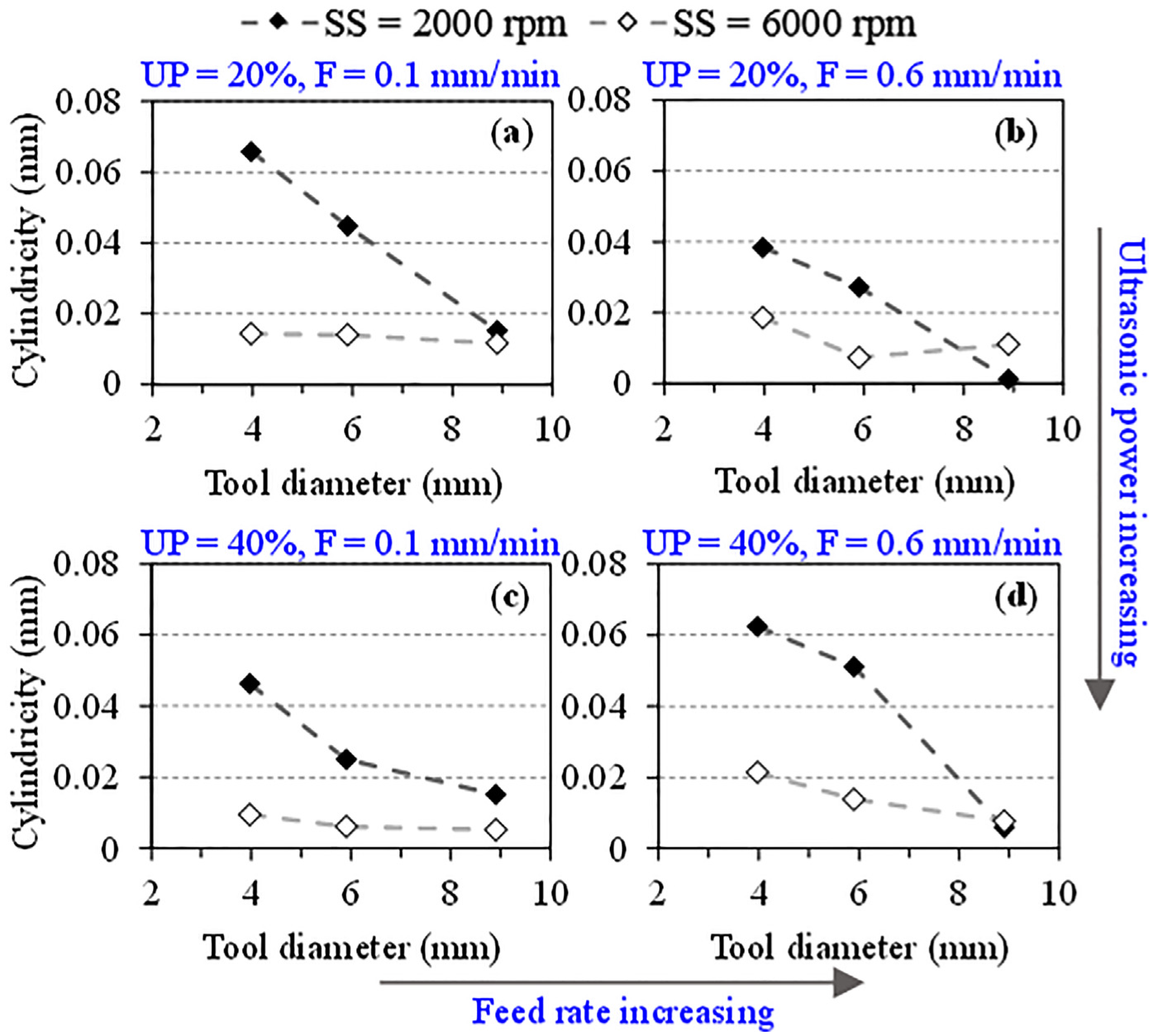
(a)–(d) Variation in cylindricity error with tool diameter at given levels of spindle speed, ultrasonic power, and feed rate.
The effect of SS on overcut error is presented in Figure 7. Overall, there is a decrease in the overcut error with the increase in the SS except at the combination of higher UP (40%) and higher feed rate (0.6 mm/min) where there is a slight increase in the overcut error. Comparing Figure 7(a) and (b) and (a) and (c), it can be commented that both feed rate and UP have a minor influence on the variation in the overcut error along with the increase in the SS. However, at UP of 40% and feed rate of 0.6 mm/min, there is a substantial reduction in the overcut error only at the SS of 2000 r/min as can be seen by comparing Figure 7(b) and (d) and (c) and (d).

(a)–(d) Variation in overcut error with spindle speed at different levels of ultrasonic power and feed rate; tool diameter D = 5.90 mm.
An overview of the influence of changing the tool diameter along with the UP and feed rate at different SSs is shown in Figure 8. At lower SS (2000 r/min), lower feed rate (0.1 mm/min), and both the levels of UP employed, there is a monotonic decreasing trend of the overcut error with the increase in the tool diameter as shown in Figure 8(a) and (c). Whereas at higher feed rate (0.6 mm/min) there is first a slight increasing and then a decreasing trend at lower UP (20%) and a monotonic increasing trend at higher UP (40%) as demonstrated in Figure 8(b) and (d), respectively, for lower SS of 2000 r/min. On the other hand, at higher level of SS (6000 r/min), there is a consistent trend of overcut error, that is, first decreasing and then increasing with the tool diameter at any combination of UP and feed rate (see Figure 8). Moreover, like the cylindricity error, the effect of tool diameter significantly weakens at higher SS. At lower SS (2000 r/min), feed rate and ultrasonic speed seem to affect more the trend of variation in the overcut error than its magnitude, while there is trivial influence of varying these parameters on the overcut error at higher SS (6000 r/min).

(a)–(d) Variation in overcut with tool diameter at given levels of spindle speed, ultrasonic power, and feed rate.
It can be observed in Figures 7 and 8 that overall both cylindricity and overcut error reduce with the increase in the SS and the tool diameter. Furthermore, for a particular selection of the RUM input parameters, the cylindricity error could be reduced to as low as 1.2 µm (see Figure 6(b)). However, the overcut error could not be reduced than 112 µm as can be seen in Figure 7(d). This is due to the reason that the tool outer diameter values expressed in Table 1 are nominal values, whereas there are diamond abrasives which would be higher than these levels and lower as well. This could easily be observed in Figure 9 where an averaged scanned profile of the diamond bonded drill is presented, elaborating the diamond abrasives both higher and lower than the mean level of the drill. Once the hole surface is swiped by diamond abrasives which are higher than the mean level, an overcut is generated. Overcut error is further amplified by the lateral vibrations of the tool and the selected levels of feed rate and UP. However, the overcut error could be offset by selecting a drill smaller in diameter by the amount of overcut error to be produced at a particular selection of input parameters.

Averaged scanned profile of a rotary ultrasonic drill (D = 3.97 mm).
Figure 10 shows a complete picture of the effect of the RUM parameters on the tool wear. It can be seen in Figure 10(a) that at lower UP (20%) and lower feed rate (0.1 mm/min), the tool wear first increases and then decreases with the increment in the SS for all the tool diameters used. Keeping the lower UP (20%) and increasing the feed rate to 0.6 mm/min (see Figure 10(b)), the tool wear expresses diverse trends for different tool diameters with the increase in the SS; a monotonic increasing trend for tool diameter of 3.97 mm, first increasing and then decreasing for tool diameter 5.9 mm and first decreasing and then increasing for tool diameter of 8.9 mm. Conversely, as the UP is increased to 40%, the tool wear shows a consistent pattern of first decreasing and then increasing with the increase in the SS for both the feed rates used as demonstrated in Figure 10(c) and (d) except for tool diameters of 3.97 mm at lower feed rate where it continuously decreases.
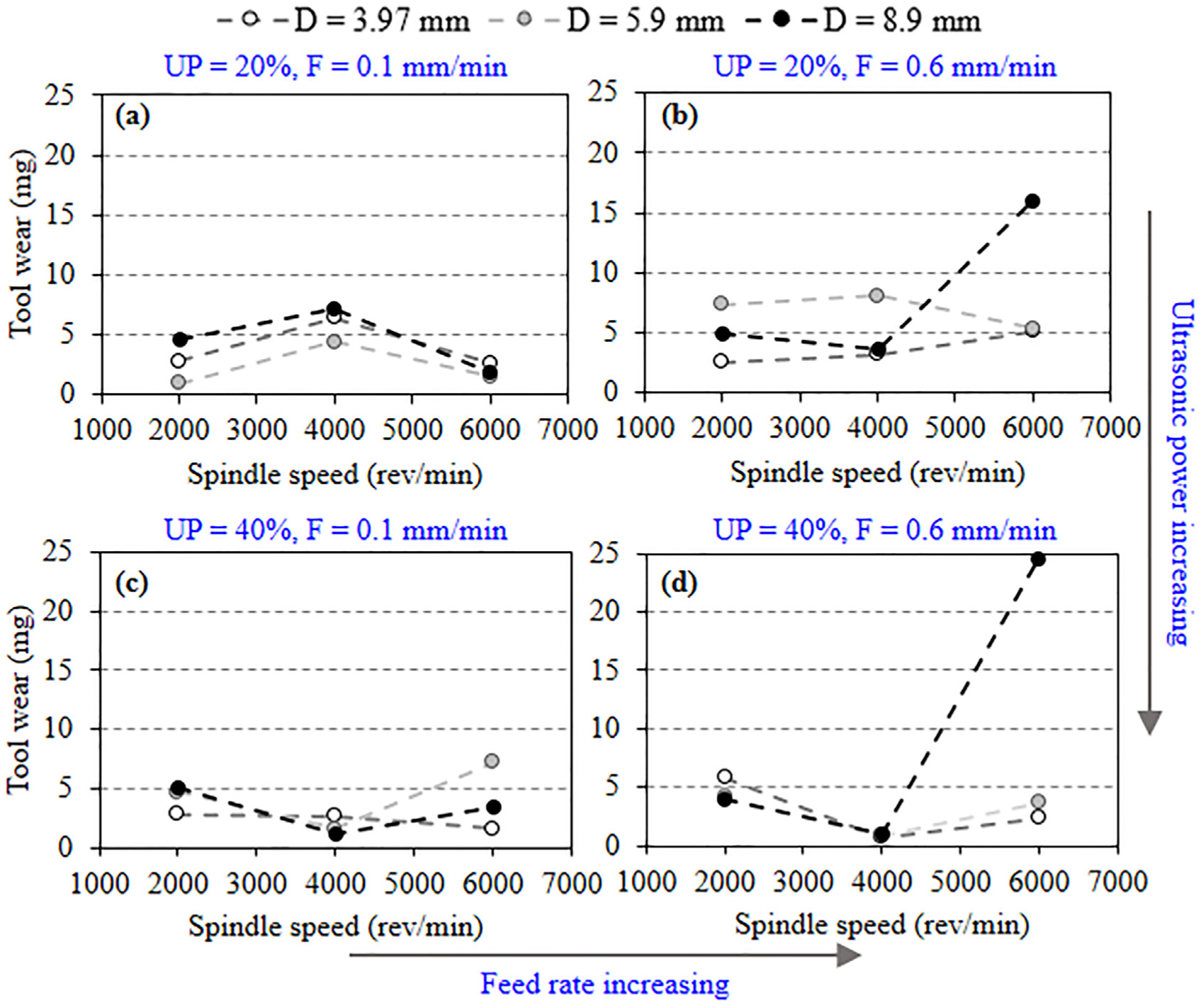
(a)–(d) Variation in tool wear with spindle speed at different levels of ultrasonic power, feed rate, and tool diameters.
It can also be seen by comparing Figure 10(a) and (b) and (c) and (d) that generally there is an increase in tool wear with the increase in the feed rate which is in line with the previously reported results in Cong et al. 14 However, there are some cases where tool wear decreases with the increase in the feed rate. For instance, for tool diameter 5.9 mm at higher UP (40%), the tool wear is reduced when the feed rate increases from 0.1 to 0.6 mm/min. Furthermore, it can also be noted that there is a sharp increase in tool wear with increment in UP and feed rate at a combination of highest SS and tool diameter. This can clearly be seen by comparing Figure 10(a) and (b) and (b) and (d) where there is a rapid increase in tool wear by increase in either feed rate or UP at SS of 6000 r/min and tool diameter 8.9 mm. Consequently, this shows that while machining with higher tool diameters and higher feed rate, lower SS and ultrasonic level are recommended to avoid excessive tool wear. This also reveals that there is a significant interaction among RUM machining parameters, and these interactions considerably affect the output responses.
Figure 11 shows the explicit effect of tool diameter on the tool wear at various combinations of UP and feed rate. Tool wear shows different trends with increase in tool diameters varying from first decreasing and then increasing (see Figure 11(a)), first increasing and then decreasing (see Figure 11(b)), and monotonically increasing and monotonically reducing as shown in Figure 11(c) and (d), respectively. In addition, it can be observed in Figures 10 and 11 that UP and feed rate can have both increasing and decreasing effects on the tool wear in combination with the SS and tool diameter. For example, comparing Figure 11(b) and (d), with the increase in the UP, the tool wear increases for tool diameter of 3.97 mm and reduces for tool diameters of 5.90 and 8.90 mm.

(a)–(d) Variation in tool wear with tool diameter at given levels of ultrasonic power and feed rate; spindle speed = 2000 r/min.
It should be noted that unlike in conventional machining where tool wear continuously increases with the increase in cutting speed (SS and tool diameter),7,25 the tool wear could even have a decreasing trend in RUM with the increase in the cutting speed at some combinations of UP and feed rate (see Figures 10 and 11). This is due to the fact that in RUM, tool wear is not only a function of cutting speed rather it is significantly affected by the level of the UP and feed rate selected.
Figure 12 shows the surface integrity analysis of the rotary ultrasonic drilled holes. Figure 12(a) and (b) compares the effect of increasing the UP on the surface of the drilled holes. It can be seen that at lower level of the UP (20%), significantly distorted and grooved morphology is produced. Prominent scratches along the tool feed direction can also be noticed along with severe re-deposition of the chips on the machined surface. In contrast, at high level of UP (40%), a clean and uniformly machined surface is produced. This is attributed to the fact that at higher UP, lower cutting forces are produced 21 resulting in reduced scratching action of the tool against the workpiece surface and generating a smoothed morphology. Figure 12(c) and (d) highlights the effect of the SS on the surface integrity. At lower level of the SS (2000 r/min), a smoothed surface (groove-less) is produced with no traces of re-deposited chips. However, a large amount of re-deposited chips are observed in case of higher SS (6000 r/min). This could be due to the reason that at higher SS, the coolant does not get enough time to flush out the chips. Consequently, the chips are trapped between the tool and the workpiece surface and are welded against the workpiece surface. The effect of feed rate can be observed by comparing Figure 12(e) and (f). As the feed rate increases, the scratches are prominently increased and more grooved morphology is observed in Figure 12(f). Furthermore, a smooth and uniform hole exit edge could be seen at lower feed rate and considerably chipped exit edge is formed at higher feed rate leading to poor quality of the hole. This is due to the fact that at high feed rate, higher cutting force is produced along the hole axial direction and the cutting tool exerts more pressure on the hole before exiting the hole resulting in chipping/breaking of the hole exit edge. The increase in exit edge chipping size with feed rate has also been reported for brittle materials. 15 Figure 12(g) and (h) compares the effect of increasing the tool diameter on the surface quality of the drilled holes. The key differences observed in both the cases are as follows: (1) at higher tool diameter, the phenomenon of chip re-deposition markedly increases and (2) the surface is more non-uniformly grooved when higher tool diameter is used. This is a similar trend as observed in Figure 12(c) and (d) that as the SS increases, the chips’ re-deposition on the machined surface increases.
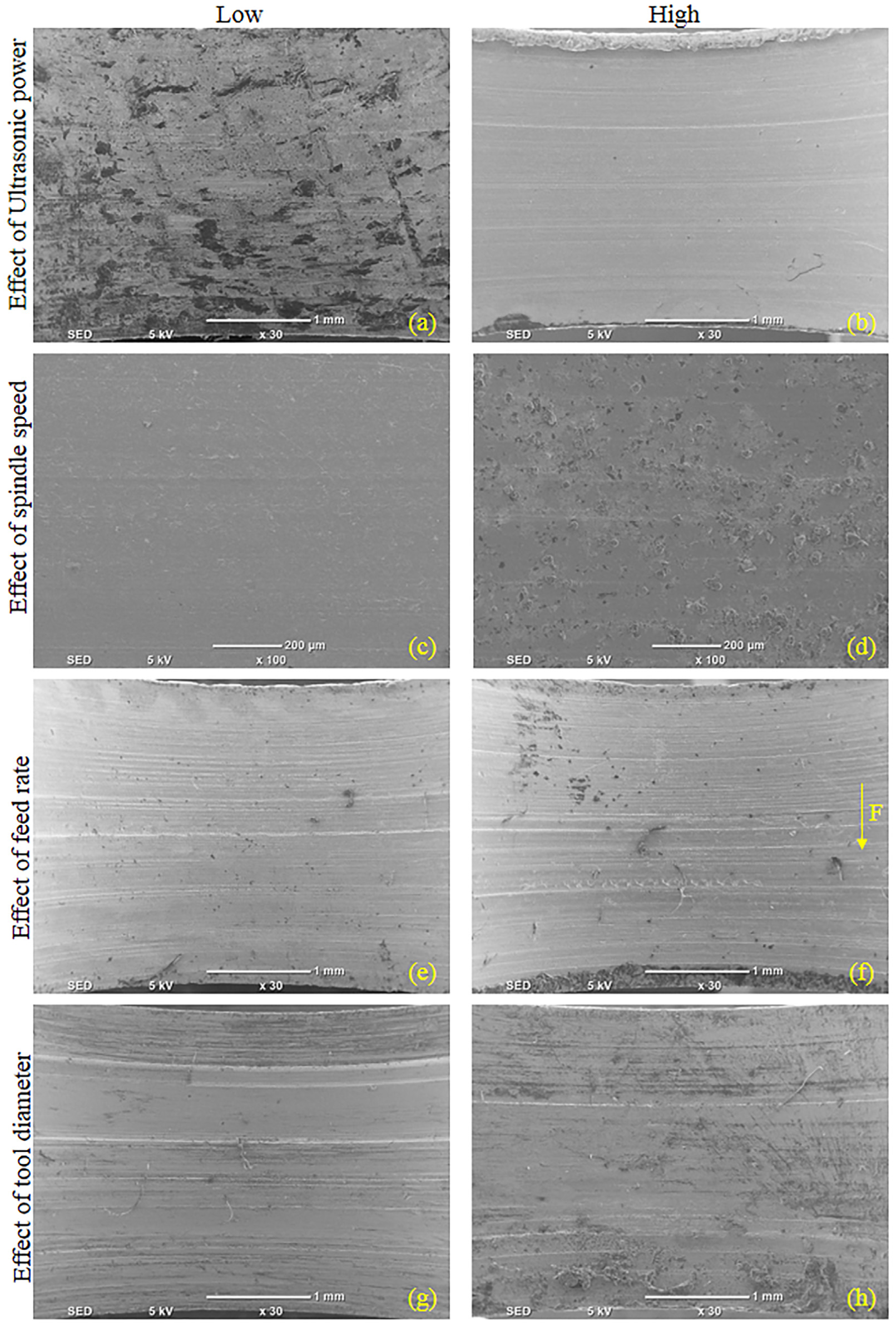
Scanning electron micrographs of the drilled holes at low and high levels of the input parameters: (a) SS = 4000 r/min, D = 9 mm, UP = 20%, and F = 0.1 mm/min; (b) SS = 4000 r/min, D = 9 mm, UP = 40%, and F = 0.1 mm/min; (c) SS = 2000 r/min, D = 9 mm, UP = 20%, and F = 0.1 mm/min; (d) SS = 6000 r/min, D = 9 mm, UP = 20%, and F = 0.1 mm/min; (e) SS = 4000 r/min, D = 6 mm, UP = 20%, and F = 0.1 mm/min; (f) SS = 4000 r/min, D = 6 mm, UP = 20%, and F = 0.6 mm/min; (g) SS = 2000 r/min, D = 6 mm, UP = 40%, and F = 0.6 mm/min; and (h) SS = 2000 r/min, D = 9 mm, UP = 40%, and F = 0.6 mm/min.
Conclusion
This study experimentally investigates the application of the RUM process for drilling holes in Ti6Al4V alloy. The effect of RUM process parameters such as SS, UP, feed rate, and tool diameter on cutting force, hole cylindricity and overcut, and tool wear has been studied. The following conclusions can be drawn from this work:
The effect of variation in the tool diameter on the output responses in conjunction with the UP and the feed rate is found to be considerably different from that of the SS in terms of trends and/or magnitudes of the output responses.
Regarding the cutting force, a new observation compared to the earlier reports is that the cutting force can both increase and decrease with the increment in the UP depending on the used level of the SS and tool diameter. Typically at lower SS and tool diameter, an increase in UP reduces the cutting force, while at the higher SS and tool diameter, increment in the UP increases the cutting force.
Another new observation is that unlike conventional machining, tool wear can have increasing, decreasing, or non-monotonic trend with the increase in SS and tool diameter during RUM. Moreover, at higher SS (6000 rev/min) and larger tool diameter (8.90 mm), an increase in either feed rate or UP could result in a very sharp increase in tool wear.
The cylindricity error generally is found to first decrease and then increase with the SS, while decreases continuously with the increase in tool diameter. Also, the effect of tool diameters on cylindricity diminishes with the increase in SS. The cylindricity error increases with the increase in UP, while feed rate effect remains dependent on the used level of the SS and tool diameter.
The overcut error is found to be an inherent characteristic of the holes drilled by RUM. The overcut error typically reduces with the increase in both the SS and the tool diameter. However, at the higher SS, the tool diameter effect weakens and the overcut error first decreases and then increases with the increment in the tool diameter. There is usually a minor influence of the feed rate and UP on the overcut error.
The scanning electron micrograph reveals that the holes with uniform and smooth surface can be machined by RUM by selecting lower level of feed rates, higher UP, lower SSs, and tool diameters. On the contrary, holes with significantly grooved morphology and high amount of re-deposited chips are produced.
This study also reveals that the selected level of the RUM input parameters has the ability to considerably affect the influence of the other input parameters on the machining performance in terms of the variations in cutting force, hole cylindricity and overcut errors, and tool wear.
Footnotes
Acknowledgements
The author would like to acknowledge the support provided by the Deanship of Scientific Research at King Saud University, through the Research Centre at the College of Engineering.
Handling Editor: Min Zhang
Declaration of conflicting interests
The author(s) declared no potential conflicts of interest with respect to the research, authorship, and/or publication of this article.
Funding
The author(s) received no financial support for the research, authorship, and/or publication of this article.