
Abstract
The edge chipping of holes, which is induced by mechanical machining, restricts the applications of brittle materials. Rotary ultrasonic machining is considered a suitable approach to machine holes in brittle materials with a smaller edge-chipping size. However, obvious edge chipping at the hole exit in rotary ultrasonic machining remains observable. In this study, conical diamond core drills with various characteristic angles (θ) were designed to further reduce the edge-chipping size for rotary ultrasonic machining. Machining tests on quartz glass were conducted to evaluate the effectiveness of this new type of drill. Experimental results show that the conical drill can obviously reduce the edge-chipping size only when certain conditions are satisfied. The mechanism of edge-chipping reduction using a conical drill was revealed by the theoretical analysis and detailed observation of the thrust force and obtained cylinder. To guarantee the feasibility of the conical drill, its characteristic angle should exceed a critical value at a certain feed rate. A higher feed rate requires a higher critical characteristic angle. The other advantage of the conical drill is its ability to suppress the bad effects of increasing the feed rate on the stability of ultrasonic vibration.
Keywords
Introduction
As illustrated by Lv et al., 1 Nath et al. 2 and Yuan et al., 3 brittle materials, which are represented by optical glass, advanced engineering ceramics and its composites, make significant contributions in various fields such as aviation, advanced instruments and information industries because of their superior properties, such as high hardness, strength, chemical stability and wear resistance at elevated temperature. Generally, machining is necessary to make brittle materials satisfy the requirements of application and assembly. However, the experimental results of Zhang et al. 4 show that because of their high hardness and low fracture toughness, brittle materials are classified as the most difficult-to-machine materials. For products made from brittle materials, holes are a commonly required feature. In the hole manufacturing of brittle materials, edge chipping at the hole exit significantly affects the performance of the component and positioning accuracy in an assembly. Improving the efficiency and reducing the cost of drilling, these materials without enlarging the edge-chipping size remain challenging.
As suggested by Kumar, 5 rotary ultrasonic machining (RUM), which combines the material removal mechanisms of ultrasonic machining and diamond grinding, is considered best suited to manufacture holes in brittle materials. As illustrated in Figure 1, in RUM, a rotating diamond core drill is longitudinally vibrated with a small amplitude at an ultrasonic frequency (approximately 20 kHz) while feeding toward the workpiece at a constant feed rate. As reviewed by Cong and Pei 6 in comparison with conventional diamond drilling, RUM can obtain more preferable holes with reduced edge chipping and improved the surface quality at a higher material removal rate and lower energy input. However, obvious edge chipping at the hole exit in RUM remains unavoidable. 4
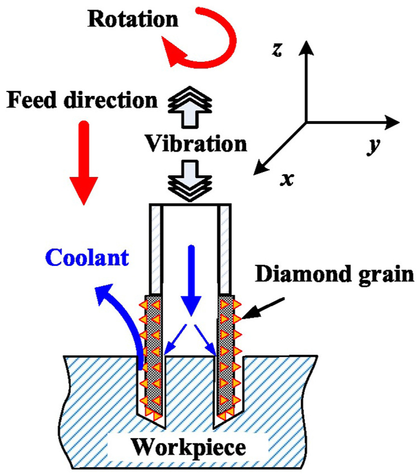
Illustration of RUM with a conical drill.
From experimental results, Gong et al. 7 suggested that adding additional support is helpful to reduce the edge-chipping size at hole exit. Using finite element model (FEM) simulations, Li et al. 8 and Chen et al. 9 also proposed that a possible solution to reduce the edge-chipping size is increasing the support length. However, the support is not always easily supplied in many machining situations. Thus, further study on the method of edge-chipping reduction without support is essential. Cong et al. 10 conducted RUM experiments on silicon, the results indicate that the cutting force (thrust force) is the main parameter that affects the edge-chipping size and a higher spindle speed or lower feed rate results in a smaller chipping thickness, which is accompanied by a weaker cutting force. Jiao et al.’s 11 experimental results on the alumina ceramics also indicate a similar relationship between edge-chipping size and thrust force with that of Cong et al. This type of dependency of the edge-chipping size on the thrust force was developed considering the machining-induced subsurface damage in a recent study by Wang et al.12,13 to predict and monitor the edge-chipping size in the machining process. To strategically minimize edge chipping, Liu et al. 14 applied the response surface analysis and desirability functions in the experimental optimization of the edge-chipping size in the RUM of ceramic materials. In addition to the processing variables, the tool design also has sufficient effects on the edge-chipping size of the machined holes. One method to further reduce the edge-chipping size is to reduce the thrust force by decreasing the wall thickness of the diamond core drill. However, it will hinder the improvement of drilling efficiency because of the limitation in drill bit strength. Simultaneously, it will increase the cost of drill bit manufacturing because of the weaker rigidity of the diamond core drill with thinner wall. The tool shape is another factor that can be optimized to reduce the edge-chipping size. Wang et al. 15 developed a novel step diamond core drill for RUM, and experimental results on the sapphire and quartz glass verified the effectiveness of this new type drill in terms of reducing the edge-chipping size. From experimental and FEM results, Qin et al. 16 reported that using conical drill was effective to reduce the edge-chipping size. However, our experiment results indicate that the conical drill does not always sufficiently reduce edge chipping, and deeper research is required to better use the conical drill.
In this study, the feasibility condition of the conical drill was investigated to further reduce the edge-chipping size for RUM of brittle materials. Modeling and experimental methods were used to investigate the mechanism of edge-chipping reduction in RUM with the conical drill.
Experiment procedure
Experiment apparatus and material
A series of experiments was performed on a rotary ultrasonic machine (Sauer Ultrasonic 50; DMG, Germany) to investigate the feasibility of edge-chipping reduction in RUM using a conical drill. The Ultrasonic 50 machine is composed of an ultrasonic spindle system, a numerical control machining system and a coolant system. The ultrasonic spindle system consists of an ultrasonic spindle (maximum rotating speed is 8000 r/min) and a power supply (maximum power is 300 W). The power supply converts a 50 Hz electrical supply to ultrasonic frequency alternating current (AC) output for the ultrasonic spindle. The ultrasonic spindle comprises a piezoelectric transducer, an amplitude transformer and a diamond core drill. The piezoelectric transducer converts the electrical input into longitudinal mechanical vibrations with a tiny amplitude at an ultrasonic frequency. The amplitude transformer and diamond core tool, which are connected together by an ER16 cone fitting, are well designed to amplify the ultrasonic vibrational amplitude to approximately 5–10 µm. Grinding fluid (Blaser, Switzerland) is used as both internal and external coolant.
As illustrated in Figure 2, a piezoelectric dynamometer (9256C2; Kistler Instrument Corp., Switzerland) was mounted on the machining table to record the drilling forces along the axial direction (namely, thrust forces) during the RUM experiments. A self-designed fixture was used to hold the specimen with two lock blocks. The fixture comprised a hole whose dimension is ϕ20 mm × 12 mm to preserve the machined cylinder when edge chipping occurs. The detected electrical signal from the dynamometer was amplified by an amplifier (5070A; Kistler Instrument Corp.) and fed to a data recorder (5697; Kistler Instrument Corp.). The recorded data were processed and displayed on a computer using a commercial and professional software (DynoWare; Kistler Instrument Corp.). The sampling frequency was 100 Hz.
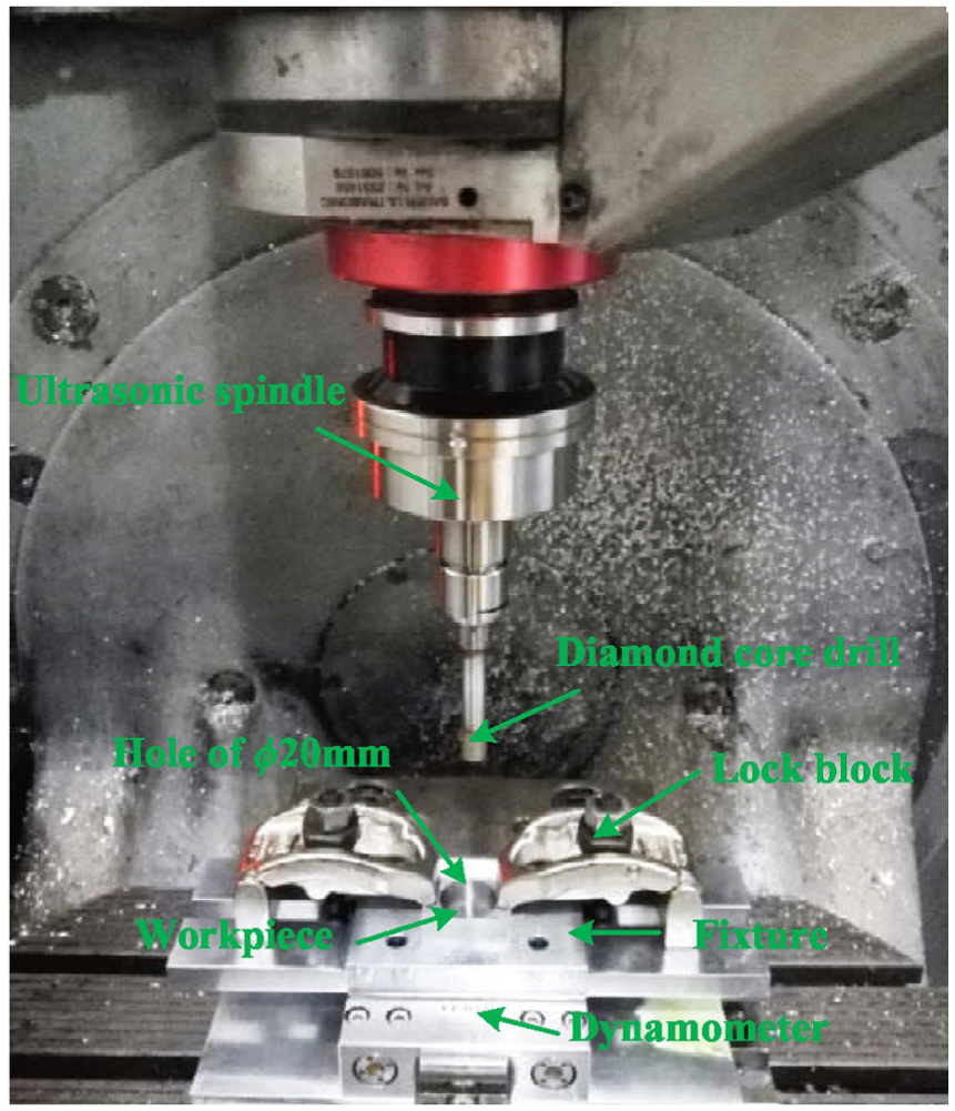
Experiment setup.
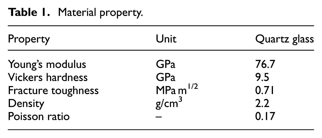
The structure of the conical diamond core drill used in the experiments is illustrated in Figure 3, where the wall thickness t, end-face thickness ts and characteristic angle θ are three key dimensions that characterize the conical drill. The drill face was electroplated with diamond particles, whose size (mesh) is D76. The workpiece materials were quartz glass, whose mechanical properties are listed in Table 1. All workpiece specimens were machined to identical initial dimensions of 30 mm × 30 mm × 8 mm.
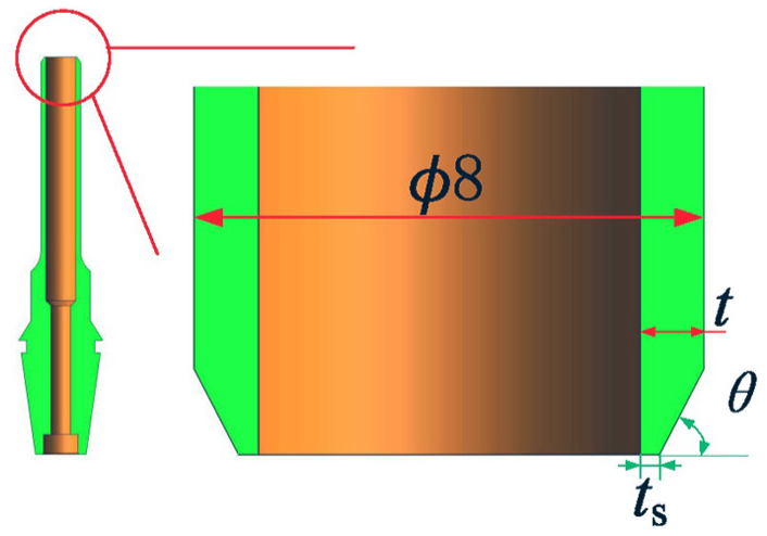
Geometry of the conical drills for rotary ultrasonic machining.
Material property.
Machining test design
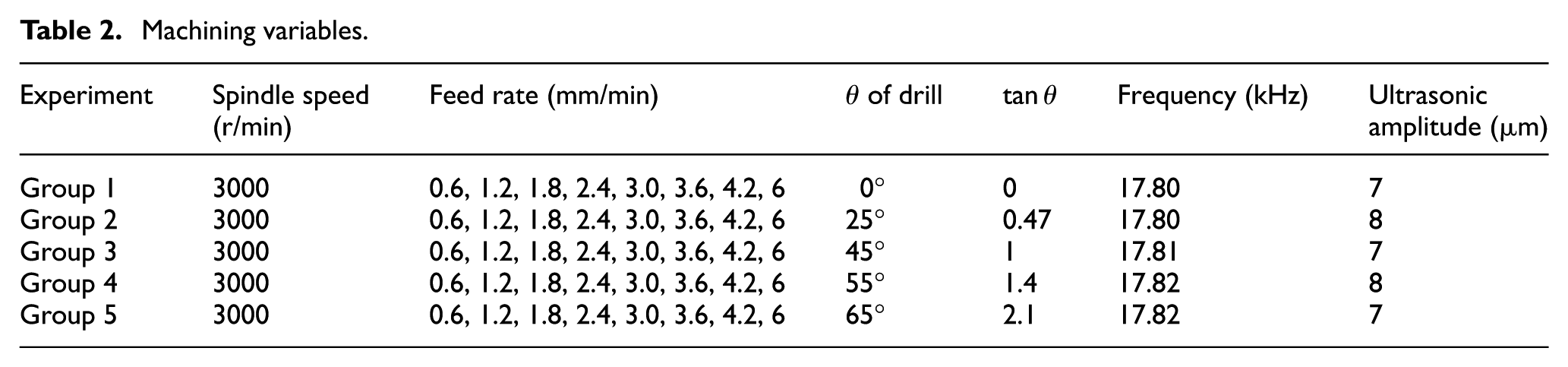
Several machining tests were performed to investigate the mechanism of edge-chipping reduction using a conical drill. The experimental variables (feed rate, taper angle of drill) are provided in Table 2. The ultrasonic amplitude of the diamond core drill was measured using a laser fiber vibrometer (LK-H008; KEYENCE, Japan). The sampling frequency to measure the ultrasonic amplitude was set at 392 kHz, and the resolution ratio was set at 0.1 µm. The ultrasonic amplitude can be derived from the obtained sine motion curve using the laser fiber vibrometer. The machining tests of each variable group were repeated three times to reduce the effects of random experiment error. As shown in Table 2, five drills were used in the experiments with different characteristic angles θ. They share identical t and ts (t = 1.2 mm, ts = 0.6 mm). Figure 4 shows the feed path of the drill tip. In Figure 4, a uniaxial coordinate system, namely, z axis, is established to mark the thrust force. The origin of coordinate is 10 mm away from the upper surface of fixture (about 2 mm away from the upper surface of workpiece). This coordinate system will be used in Figures 14, 16 and 17 in the following sections. During some experiments, the ultrasonic powers were read from the operating panel of the machine.
Machining variables.
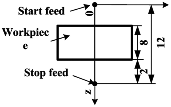
Feed path.
It is recommended that the experiments should be conducted under the same ultrasonic frequencies and amplitudes. However, the used ultrasonic machine (Ultrasonic 50; DMG) cannot adjust the ultrasonic amplitude freely by changing the input voltage. At the same time, in order to maximize the efficiency of ultrasonic machine, it is usually tuned at its resonant frequency where the ultrasonic amplitude reaches the maximum value. In the experiments of this study, the same tuning method was used. And for the ultrasonic machine using different tools, the resonant frequencies are generally not identical as well as the ultrasonic amplitudes. That is why some difference in the ultrasonic frequencies and amplitudes existed as shown in Table 2. However, based on our recent study, the effects of ultrasonic frequency (around 20 kHz) and amplitude on the edge-chipping size were not noticeable. 12 Thus, those differences in the ultrasonic frequencies and amplitudes are small enough to be neglected to some extent.
As shown in Figure 5, because of the hollow structure of the drill, a cylinder and a hole can be obtained in RUM. The edge-chipping size is an important criterion to evaluate the quality of a hole. The edge chip width ds is the main parameter to define the degree of edge chipping. ds is defined using the following equation

where Dm is the maximum diameter of the edge-chipping profile and Dh is the hole diameter. The other parameter that is usually used to characterize the degree of edge chipping is the edge-chipping thickness dt. However, it has been reported that ds increases monotonically with dt. 3 Thus, in this article, only ds was used. An optical microscope (55XA; Shanghai Optical Instrument Factory No. 6., Shanghai, China) and a Vernier caliper were used to measure the edge-chipping size at the exit side of each machined hole.
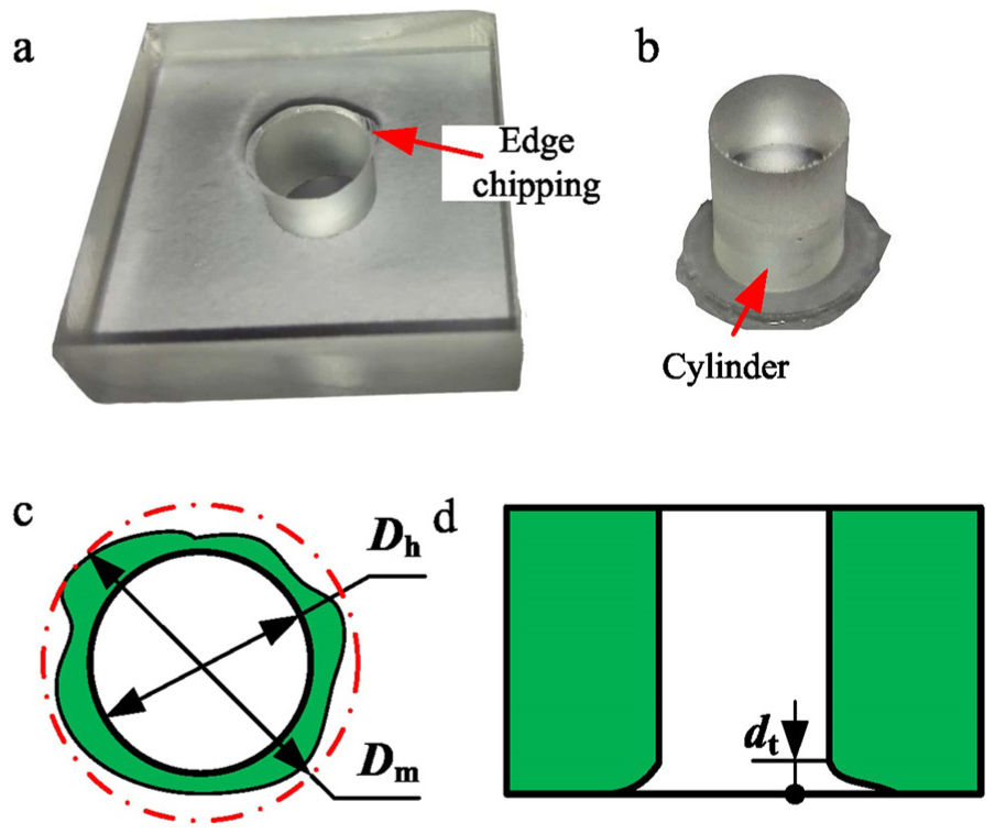
Characteristics of edge chipping and the cylinder: (a) morphology of edge chipping; (b) morphology of obtained cylinder; (c) definition of edge chipping width; (d) definition of edge chipping thickness.
Results and discussion
Feasibility of edge-chipping reduction using a conical drill
Edge-chipping results
The drilling efficiency and hole exit quality are two competing aspects in the hole manufacturing of brittle materials. Generally, a higher drilling efficiency leads to a relatively larger edge-chipping size. For the RUM of brittle materials, the feed rate is the only parameter that determines the drilling efficiency. Good knowledge about the quantitative relationship between the feed rate and the hole exit quality is notably helpful to optimize the processing parameters.
Figure 6 shows the edge-chipping size at different drilling efficiencies (represented by the feed rate) for quartz glass using different drills with various characteristic angles in RUM. Figure 7 shows the edge-chipping reduction rate using conical drills (θ > 0°) with respect to that using common drills (θ = 0°). When a common drill is used, the edge-chipping size increases with the increasing feed rate, except when the feed rate is 0.6 and 1.8 mm/min. This result is inconsistent with our ordinary understanding. In most cases, the use of a conical drill can obviously reduce the edge-chipping size. Sometimes, the reduction rate can be 80%, for example, when θ = 55° and feed rate = 4.2 mm/min. However, the use of a conical drill sometimes cannot reduce the edge-chipping size and even enlarges it. For example, when θ = 45° and feed rate = 3.6 mm/min, the reduction rate is negative, and more serious hole exits are observed. Deterioration of the hole exit quality can also be observed when other conical drills are used except when θ = 65°.
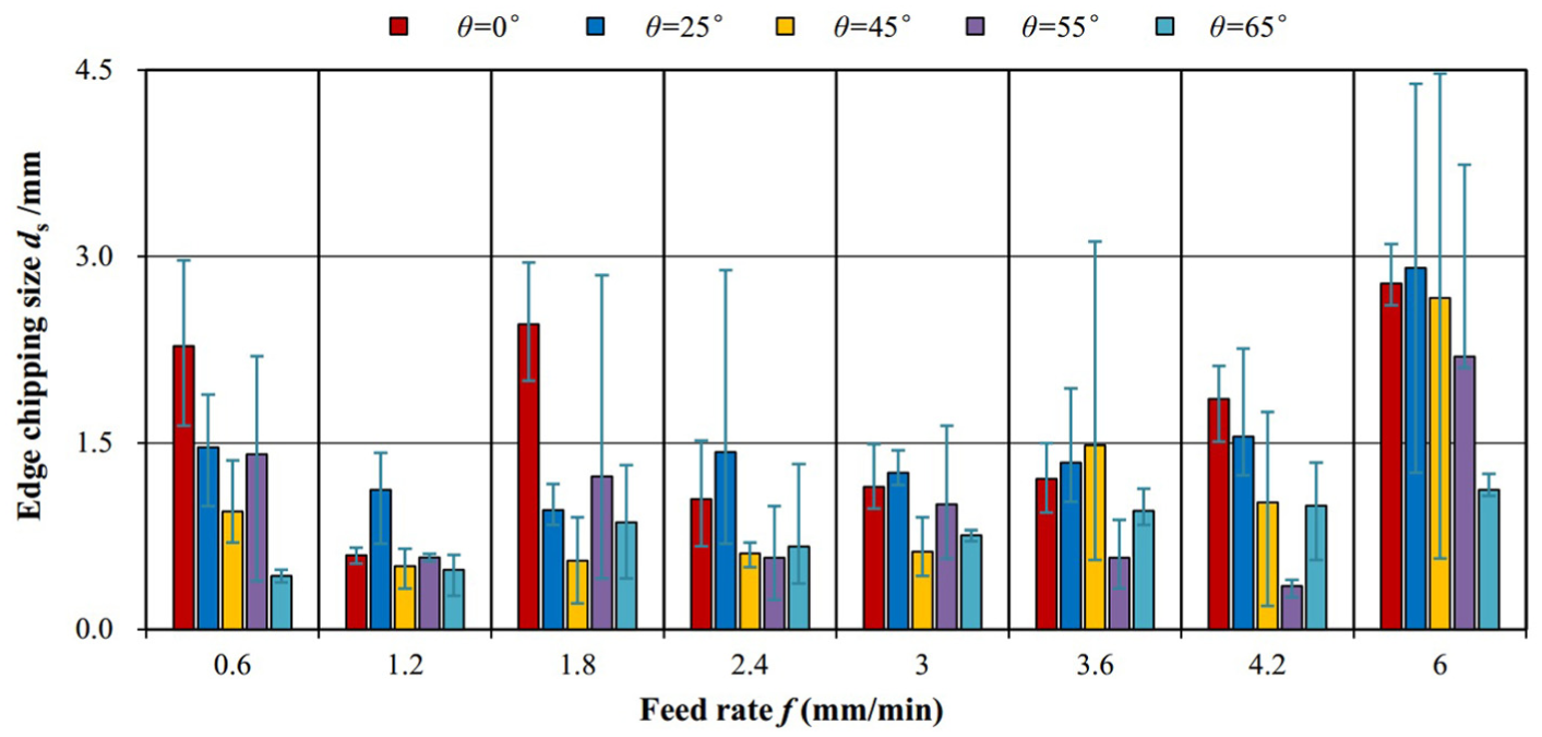
Edge-chipping size versus feed rate.
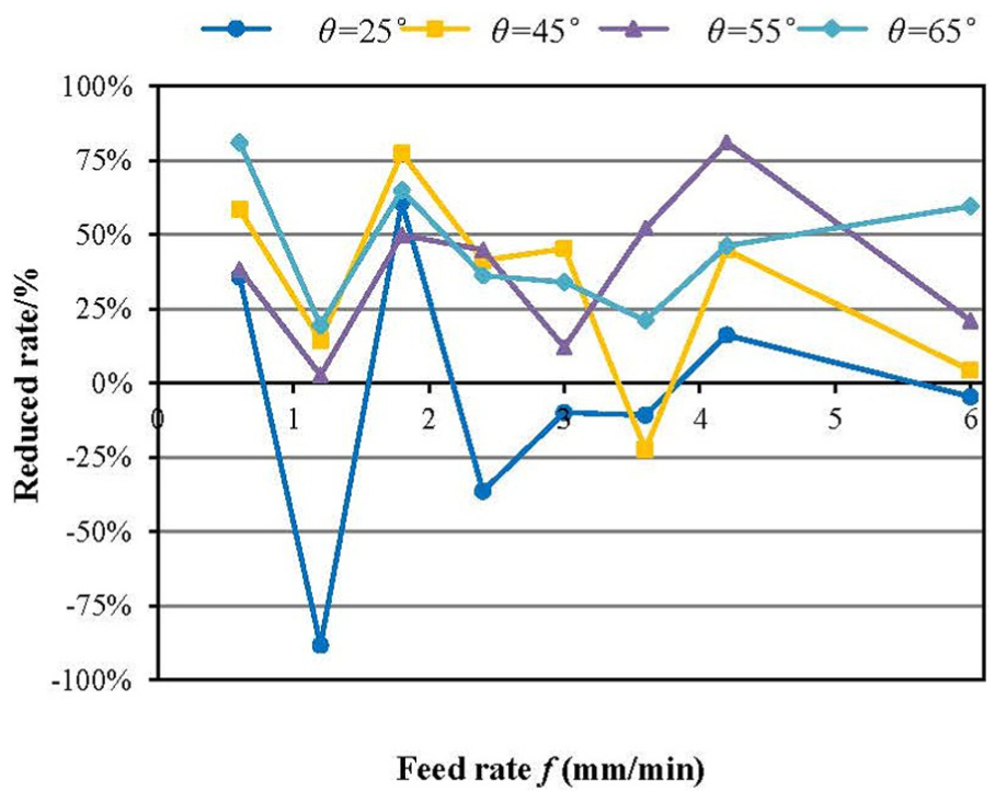
Edge-chipping reduction rates with different conical drills.
Critical characteristic angle
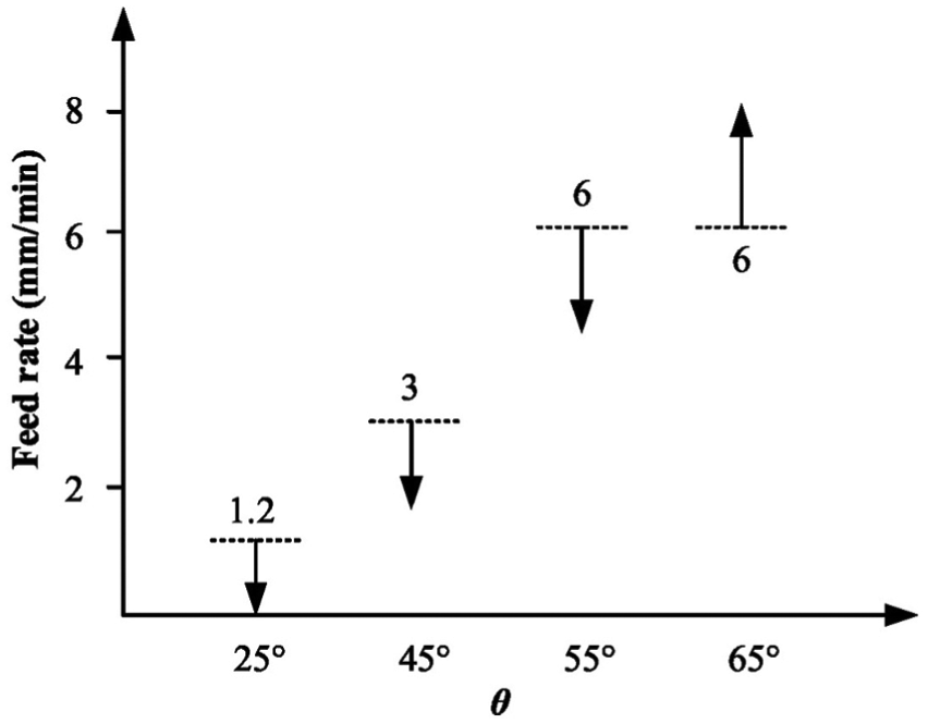
As shown in Figures 6 and 7, only when the feed rate is 0.6 or 1.8 mm/min, the edge-chipping size can be reduced using a conical drill with θ = 25°. Considering the abnormality of using a common drill when the feed rate is 1.8 mm/min, the feed rate of 1.2 mm/min can be considered a critical value, which should not be reached or exceeded to guarantee the effectiveness of the conical drill of θ = 25°. Similar critical values of the feed rate for conical drills with other characteristic angles can also be found. A critical feed rate can be characteristic when the deterioration of the hole exit first appears. Using this method, the critical feed rates of conical drills are illustrated in Figure 8. Particularly, when θ = 65°, even at the largest feed rate in the experiments, the edge-chipping size is obviously reduced.
Critical feed rate of different conical drills.
However, the results in Figures 6 and 7 also demonstrate that when a feed rate is decided, there is a critical characteristic angle that should be exceeded to guarantee the effectiveness of edge-chipping reduction using conical drills.
Mechanism of edge-chipping reduction using a conical drill and its verification
Mechanism of edge-chipping reduction
The mechanism of edge-chipping formation at the hole exit in RUM was proposed and verified by Wang et al. 12 As shown in Figure 9, under the combined driving force of all active abrasives, the micro cracks, which are induced by mechanical impacts, begin to propagate to a macro crack and initiate the edge chipping.
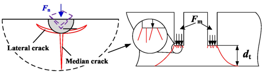
General mechanism of edge-chipping formation.
For the mechanism of edge-chipping reduction using a conical drill, this general mechanism of edge-chipping formation in RUM can be applied. Considering an ideal situation where an ideal conical drill is used, Figure 10 illustrates its drilling process. It is assumed that the abrasives uniformly distribute on the drill surface, and the thrust force uniformly and continuously distributes on the workpiece.
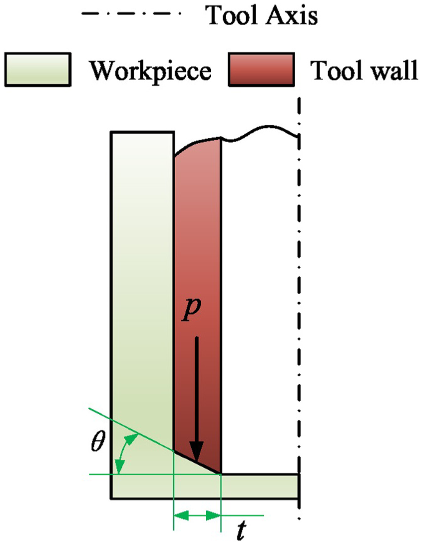
Illustration of the drilling process using an ideal conical drill.
Based on the modeling results of the edge-chipping size for RUM, the dependence of the edge-chipping size on the thrust force can be expressed as

where ds is the edge-chipping size in millimeter; k1 and α are the proportionality and index coefficients, respectively; p is the thrust force density per unit drill thickness as shown in Figure 10 and t is the wall thickness of the diamond core drill in millimeter. In the modeling process of reference by Wang et al., the wall thickness of the diamond core drill was 1 mm. Thus, in this study,
The edge-chipping size is proportional to the undrilled thickness dt

Substituting equation (2) into equation (1), one can obtain the dependence of the critical undrilled thickness on the thrust force

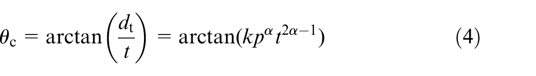
where k = k1 k2. For a certain thrust force pt, when the undrilled thickness dt satisfies the relationship in equation (3), edge-chipping forms. Thus, the critical taper angle can be derived as
To confirm that this taper angle is critical, the following derivation is performed. As shown in Figure 11 (left), if a new edge chipping does not initiate in that situation, the following equation is satisfied

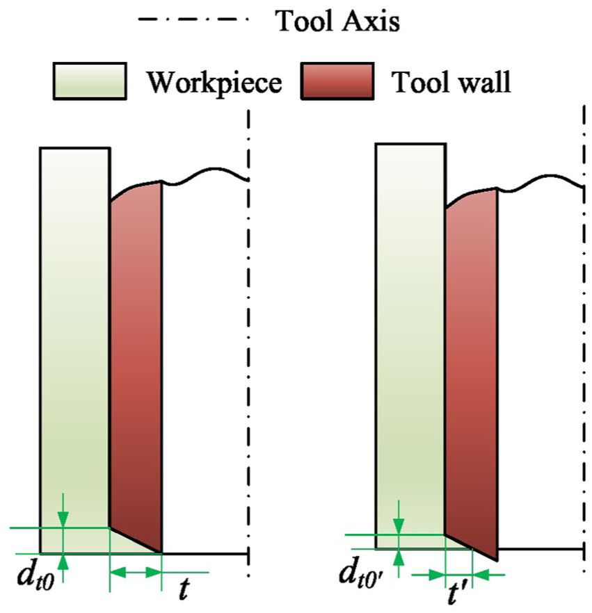
Critical condition of the ideal conical drill.
From Figure 11, a basic proportional relation is obtained
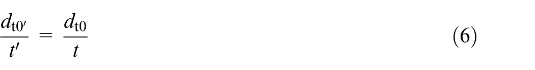
Substituting equations (5) and (6) into
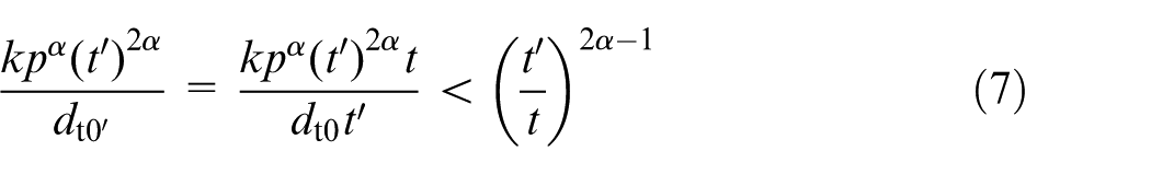
Because

Equation (8) indicates that for an edge-chipped hole exit, a new edge chipping will not initiate in the reprocessing course of the conical face because in this type of processing course, the thrust force decreases with the decreasing undrilled thickness. This theoretical analysis reveals the mechanism of edge-chipping reduction for RUM using a conical drill.
Now, an actual drill is used as shown in Figure 12(a), and a plain face of length (ts in millimeter) is required to avoid serious tool wear. One does not want to see the edge-chipping forms like the mode in Figure 12(c) but like the mode in Figure 12(b). To guarantee the mechanism of edge-chipping reduction of the conical drill, the following equations should be satisfied


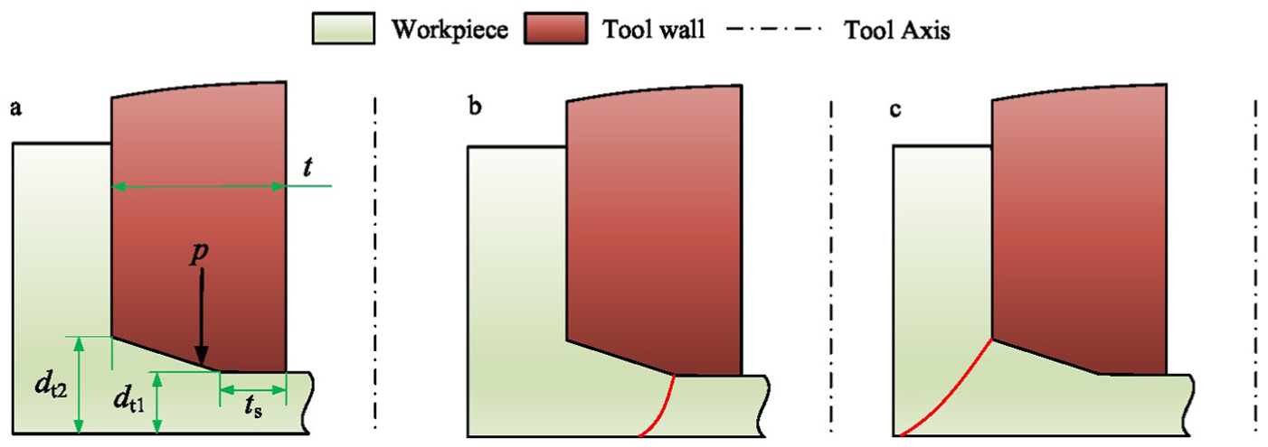
Critical condition of actual conical drill: (a) definition of feature size; (b) edge chipping formation mode 1; (c) edge chipping formation mode 2.
When equality holds in equation (10), a critical taper angle is obtained
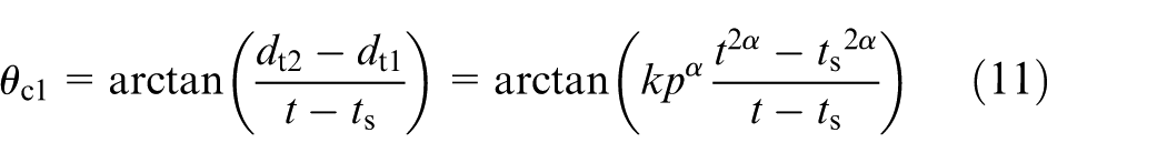
The other critical angle is

As shown in Figure 13,
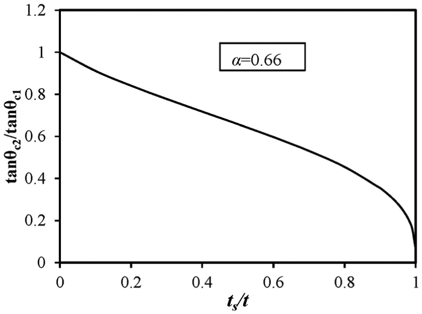
Comparison of two critical characteristic angles.
Equation (11) indicates that a larger p corresponds to a higher critical angle. Generally, a bigger feed rate induces a larger p. Thus, a higher critical angle is required at a bigger feed rate, which is consistent with the experimental results.
Verification and discussion
Table 3 shows the typical images of the hole exit and cylinder using both common drill (θ = 0°) and conical drill (θ = 45°). Compared with the common drill at a feed rate of 3.0 mm/min, the conical drill obviously reduces the edge-chipping size. However, when the feed rate increases to 3.6 mm/min, the results change. The edge-chipping size with a conical drill abruptly increases from 0.55 to 3.12 mm, which is much larger than that when a common drill is used. This result indicates the change in edge-chipping formation mode from the mode in Figure 12(b) to that in Figure 12(c). The images of the cylinders also verify this mechanism. The geometrical shape of the obtained cylinder using a conical drill with a feed rate of 3.6 mm/min appears notably different from the others, which indicates an edge-chipping formation mode in Figure 12(c).
Images of the hole exit and cylinder when different drills were used.
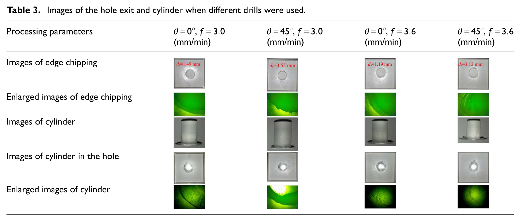
Figure 14 shows the comparison of the thrust force characteristic when different drills were used. In Figure 14, at the hole exit, the thrust force abruptly decreases for all of the drilling conditions indicating the formation of edge chipping. By detailed observation, it can be found that the thrust force decreases directly to a certain stable value when θ = 0° for a feed rate of 3.0 mm/min. However, when a conical drill is used with a feed rate of 3.0 mm/min, the thrust force did not decrease directly to a certain stable value. On the contrary, there is a slight decrease process of the thrust force, this is due to the existence of reprocessing process as shown in Figure 11 (right). This type of reprocessing process also appears when the feed rate is 3.6 mm/min because the edge chipping is not circular symmetrical as shown in Table 3. Thus, the reprocessing process is not a sufficient condition to obtain a superior hole exit; however, an edge-chipping formation mode in Figure 12(b) is also required.
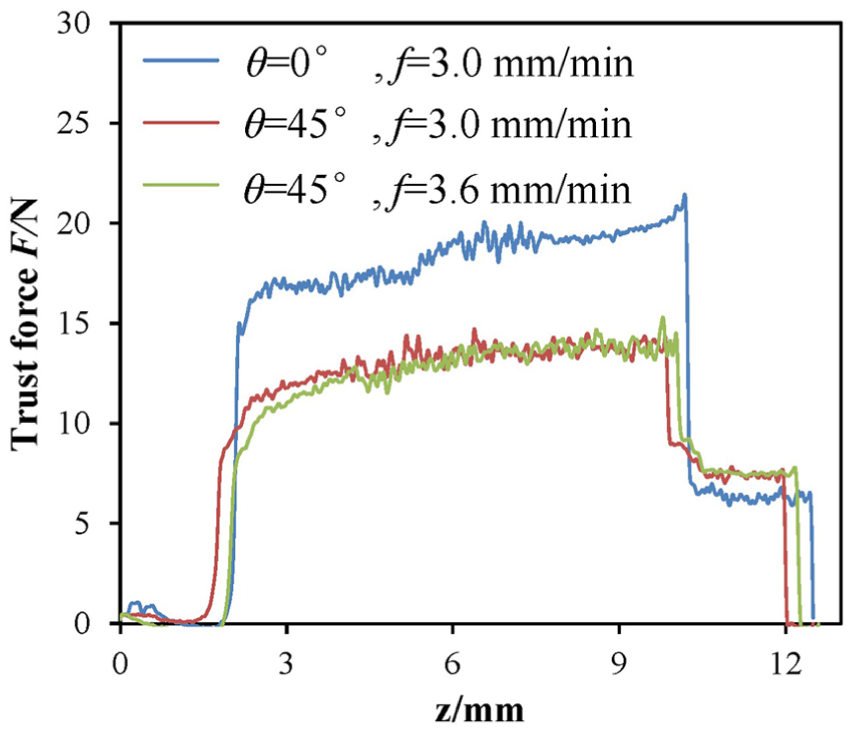
Comparison of the thrust force characteristic when different drills were used.
This theoretical analysis is based on the assumption that the diamond particles are continuously distributed on the surface of the drill. However, the diamond particles are discretely distributed on the surface. When the face dimension is relatively much larger than the diamond particle dimension, the assumption of continuous distribution of diamond particles is reasonable. However, when the face dimension is close to the diamond particle dimension, this assumption of continuous distribution of diamond particles is arbitrary. Thus, at the end moment of the reprocessing course of the conical face, as shown in Figure 15, a new but tiny edge chipping can initiate again. The experimental evidence is shown in Table 3: the geometrical shape of edge chipping using a conical drill (θ = 0°) at a feed rate of 3.0 mm/min is serrated, which is notably different from other smooth edge chippings.
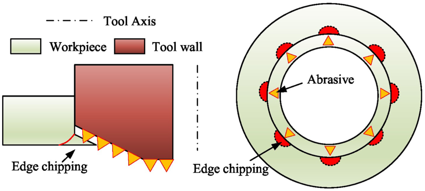
Mechanism of edge-chipping formation of the conical drill.
Improvement in stability of the ultrasonic vibration using a conical drill
The ultrasonic amplitude and frequency are two key characteristic parameters for RUM. Generally, the machine is excited at a resonance frequency to maximize the ultrasonic amplitude. This excitation is generally made in the no-load mode. However, the mechanical load on the tool during machining may induce the instability of the ultrasonic machine.
Figure 16 shows the thrust force in different feed rates when a common drill was used (θ = 0°). Because the drill used is without conical face, all the thrust decreases directly to a stable value at the hole exit. However, an abrupt increase in thrust force during the machining process can be observed when the feed rate is 3.6, 4.2 and 6.0 mm/min. With the increase in feed rate, this type of abrupt increase occurs increasingly earlier. To reveal the mechanism of the abrupt increase in thrust force, the ultrasonic power was recorded during the machining process. Figure 17 shows the variation in ultrasonic power (unit of 1 W) when a common drill is used at feed rates of 4.2 and 6.0 mm/min. Ultrasonic powers were only recorded when the force significantly deviates. The detailed small variation in ultrasonic power during the process was neglected. In Figure 17, when the cutting force abruptly increases, the ultrasonic power abruptly decreases to approximately 12–13 W, which indicates a serious decrease in ultrasonic amplitude. However, at the hole exit, the ultrasonic power abruptly increases to a relatively high level, which indicates an increase in ultrasonic amplitude. This event may result from the changes in resonant frequency of the ultrasonic machine because of the mechanical load during the machining process. As demonstrated by Astashev et al., 17 there is a maximum driving force to guarantee the stability of the ultrasonic process, which is similar in RUM. The evidence to verify this similarity is shown in Figure 16: with the increase in machining depth, the thrust force gradually increases. Comparing the forces when instability occurs, it can be found that they are almost identical, which also explains why a larger feed rate is easier to induce such instability of the ultrasonic process.
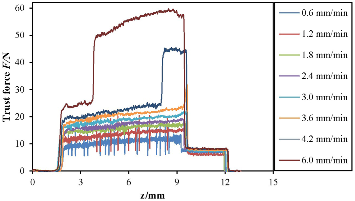
Abrupt increase in thrust force at different feed rates when a common drill (θ = 0°) was used.
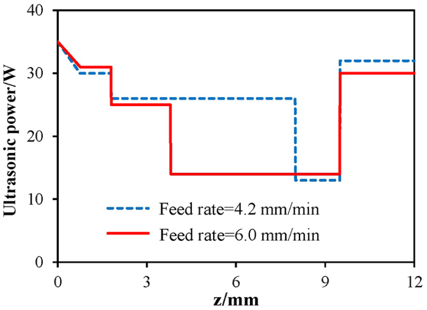
Ultrasonic power variation when a common drill (θ = 0°) was used.
Figure 18 shows the edge-chipping force variation with increasing feed rate when different drills were used. The edge-chipping force is defined as the average force at the hole exit. It can be calculated by the following equation
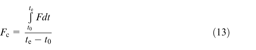
where Fc is the edge-chipping force, te is the time when the thrust force drops abruptly, t0 is a time which can be calculated as
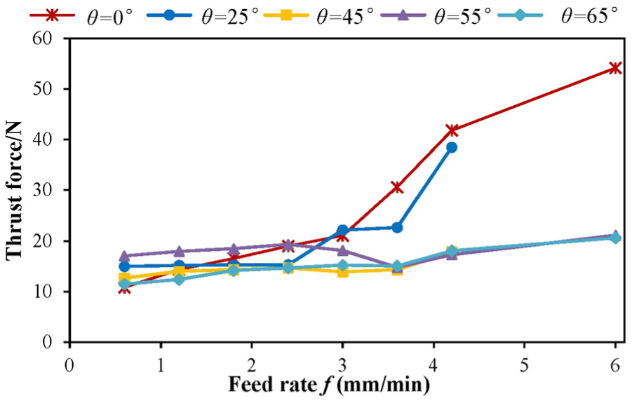
Edge-chipping force versus feed rate using different drills.
In Figure 18, some abrupt increase in edge-chipping force can be observed when θ = 0° and θ = 25°. To guarantee the effectiveness of ultrasonic vibration, the feed rates should not exceed 3.0 mm/min when θ = 0°, and it should not exceed 3.6 mm/min when θ = 25°. However, when θ ≥ 45°, no abrupt increase in edge-chipping force can be observed. Thus, the conical drill can help suppressing the bad effects of increasing the feed rate on the stability of the ultrasonic vibration because of the relatively smaller thrust force. A higher feed rate can be set when a conical drill is used.
Concluding remarks
In this study, conical diamond core drills with various characteristic angles (θ) were designed to further reduce the edge-chipping size for RUM. Machining tests on quartz glass were conducted to evaluate the effectiveness of this new type of drill. The mechanism of edge-chipping reduction using a conical drill was revealed by theoretical analysis and detailed observation of the thrust force and obtained cylinder. Several conclusions are drawn from this study:
The edge-chipping size can be obviously reduced using a well-designed conical drill. However, this type of reduction is not always observed if the drill geometry and feed rate are not well selected.
To guarantee the feasibility of the conical drill, the feed rates should not exceed a critical value at a certain characteristic angle. However, the characteristic angle should exceed a critical value at a certain feed rate. A higher feed rate requires a higher critical characteristic angle. When the critical condition is satisfied, the edge-chipping formation location will change from the end face to the border of the conical face.
In the reprocessing process of the conical face, the thrust force can gradually decrease at the hole exit; this is why the conical drill can reduce the edge-chipping size. However, the reprocessing process is only effective when the edge-chipping forms at the border of the end face.
During the machining process, a serious instability of ultrasonic vibration will occur at high feed rates when a common drill is used, which results in an abrupt decrease in ultrasonic vibration and increases in thrust force and edge-chipping size. With the increasing feed rates, this phenomenon of instability occurs increasingly earlier. The conical drill is helpful to suppress the bad effects of the increasing feed rate on the stability of ultrasonic vibration.
Footnotes
Declaration of conflicting interests
The author(s) declared no potential conflicts of interest with respect to the research, authorship and/or publication of this article.
Funding
This study was financially supported by the Beijing Natural Science Foundation (Grant No. 3141001) and National Natural Science Foundation of China (Grant No. 51475260).