
Abstract
BK7 glass is an important engineering material with extensive applications in high-quality and precision transmissive optical components. However, BK7 glass is considered to be a difficult-to-cut material due to its high brittleness and nonconductivity. This article presents the use of rotary ultrasonic machining process for drilling holes in BK7 glass. No previous reports have been found in the literature to experimentally investigate the response of the BK7 glass to rotary ultrasonic drilling. The experimental investigations take into account the effect of the key rotary ultrasonic machining input parameters including the ultrasonic power, spindle speed and feed rate on the output responses of cutting force, exit chipping, surface roughness, hole cylindricity and overcut errors, and surface integrity. The results show that the input parameters within the current ranges can significantly affect the quality of the drilled holes. Moreover, the selected level of any input parameter has the ability to significantly affect the influence of the other input parameters on the output responses. Through proper selection of input parameters, holes could be drilled in BK7 glass with less fractured topography, low surface roughness (1.32 µm), low exit chipping size (0.85), and very low cylindricity (3 µm) and overcut (73.6 µm) errors.
Keywords
Introduction
BK7 glass is an important material extensively utilized in many high-quality optical applications such as lenses in various electronics. This is owing to the superior optical properties of BK7 glass, for instance, its high optical stability, optical transparency, and bubble-free property. 1 However, due to its brittleness, poor thermal and electrical conductivity, low fracture toughness, and high hardness, BK7 glass is a difficult-to-cut material and incurs high cost with traditional machining. 2 There is a key importance for identifying and developing the new machining processes capable of overcoming the challenging properties of difficult-to-cut materials for their effective utilization. When compared to conventional/nonconventional machining methods (e.g. drilling, grinding and electric discharge machining), rotary ultrasonic machining (RUM) is an alternative machining method which is of particular interest for the machining of brittle and nonconductive materials as demonstrated in previous studies.3,4 RUM is a hybrid machining process based on the combined material removal mechanisms of diamond grinding and ultrasonic machining resulting in higher material removal rates. The ultrasonically vibrating diamond-bonded tool is axially fed into the workpiece at a constant feed rate. The tools employed in RUM are through coolant to keep the tool cool and sweep away the debris during machining.
Various studies have been reported using RUM for grinding and drilling of various types of hard and brittle materials. Churi et al. 5 used RUM for drilling holes in Ti6Al4V alloy and studied the effects of spindle speed, feed rate, and ultrasonic power on the cutting force, material removal rate, and surface roughness. Cong et al. 6 employed RUM for drilling holes in carbon fiber–reinforced plastic (CFRP) composites and investigated the effect of cutting fluid and cold air on the cutting force, torque, surface roughness, and tool wear. Another study utilized RUM for drilling holes in K9 glass and compared the results with diamond drilling. 7 The results showed that the rotary ultrasonic drilling produced significantly less fracturing of the workpiece surface and much lower forces when compared with diamond drilling. Li et al. 8 reported that a reduction of 50% in the cutting forces and an increase of 10% in material removal rate could be achieved during RUM of ceramic matrix composites as compared to diamond drilling. Choi et al. 9 applied RUM for grinding Ti6Al4V, FCD700, and S45C materials and reported that lower cutting temperature and tool wear are observed when compared with conventional grinding. A study was reported to investigate the influence of rotary ultrasonic grinding parameters on surface integrity of potassium dihydrogen phosphate (KDP) crystals in terms of surface roughness and subsurface damage. Their results demonstrated that RUM can be employed for precison machining of KDP crystals achieving surface roughness as low as 33 nm. 10 Another study presented the application of RUM in surface grinding of CFRP composites. 3 The effect of rotary ultrasonic tool parameters including tool geometry, diamond abrasive size, and diamond concentration was studied on cutting force, torque, and surface roughness, and the guidelines were provided for tool selection for RUM of CFRP composites. It can be seen that in the reported studies, the performance of RUM machining process has been evaluated in terms of cutting force, material removal rate, exit chipping size, temperature generation, and tool wear. The results of these studies have proven the benefits of RUM in terms of lower cutting forces and temperatures and higher material removal rates and quality of the drilled holes when compared with the available alternative machining processes.
The application of RUM has also been demonstrated for BK7 glass. Lee et al. 11 used RUM for grinding BK7 glass and studied the effects of feed rate and ultrasonic frequency on surface roughness of the milled specimens. It was reported that the surface roughness decreases with the decrement of ultrasonic frequency and feed rate. Lv et al.12,13 studied the effect of ultrasonic vibration, spindle speed and feed rate on the cutting force and surface roughness and explained the surface formation mechanism during the rotary ultrasonic grinding of BK7 glass. The results were also compared with conventional diamond grinding process, and the superiority of RUM was illustrated over conventional grinding process in terms of lower cutting force without seriously deteriorating the surface quality of BK7 glass. Research was also conducted to investigate the effect of the spindle speed, feed rate, ultrasonic frequency, grain size, and cutting depth on the subsurface damage and surface roughness during rotary ultrasonic grinding of BK7 glass. 14 Furthermore, theoretical model for evaluating the subsurface damage depth was developed for rotary ultrasonic grinding of BK7 glass. 15
It can be seen from the reviewed literature that only few studies have been reported regarding RUM of BK7 glass and are mainly centered on the surface grinding of BK7 glass. It should be noticed that the material undergoes significantly different loading conditions in drilling process than those encountered in surface grinding. No research could be found in the literature focusing on the rotary ultrasonic drilling of BK7 glass material. Only recently, a study has been reported to use RUM for drilling holes in BK7 glass. 16 However, this study only investigates the effect of ultrasonic vibration on the hole entrance chipping and explains the chip formation mechanisms. However, this study presents in detail the experimental investigation of the response of the BK7 glass to rotary ultrasonic drilling. There are number of industrial applications which require drilling of holes in BK7 glass optics such as in optical filters, polarizers, lens, and beam splitters. 17 The main aim of this study is to systematically present the effects of the main process parameters of rotary ultrasonic drilling including spindle speed, feed rate, and ultrasonic power on the key output responses such as axial cutting force, exit chipping size, surface roughness, and hole accuracy in terms of cylindricity and overcut errors while drilling BK7 glass. This work will enhance the understanding of the RUM process specific to drilling holes in BK7 glass material.
Experimentation
Machining experiments were performed on a Sonic-Mill series 10 rotary ultrasonic machine with maximum spindle rotation speed, vibration frequency and ultrasonic power as 8000 r/min, 20 kHz, and 1000 W, respectively. Figure 1 shows the RUM setup used for the machining of BK7 glass. The RUM setup mainly consisted of three main systems which are an ultrasonic spindle system, a coolant setup, and a data acquisition system. The ultrasonic spindle system consisted of an ultrasonic spindle, a power supply, a motor and a speed controller. The power supply converted the conventional electric supply to high-frequency (20-kHz) electrical signals. The piezoelectric actuator converted high-frequency electrical signals to mechanical vibration along the direction of tool feed movement. The ultrasonic vibrations were amplified and transmitted to the rotary tool attached to the spindle which consequently vibrates with a small vertical amplitude. The amplitude of the tool vibrations was altered by controlling the power supply output. The rotational speed of the spindle was varied by adjusting the spindle motor speed controller. The cooling system provided coolant at the diamond tool and workpiece interface to reduce the cutting temperature and flushing the debris. Water-miscible Fuchs Ecocool S-HL oil was used as coolant, with a concentration of 10%.

Rotary ultrasonic machining setup: (a) zoomed-in view of the workpiece material BK7 glass in the dynamometer fixture and (b) rotary ultrasonic machine.
The input parameters that were varied during the experiments include spindle speed, ultrasonic power supply, and feed rate. While, due to the limitation of the current experimental setup, the ultrasonic vibration frequency was kept constant at 20 kHz. A single input parameter was changed at a time while others are kept constant. The input parameters and their respective values are shown in Table 1. It should be noted that the ranges of the input parameters were selected based on the preliminary trials during which only exit chipping size and surface roughness were measured. It was found that (1) going above the selected range of feed rate resulted in significantly large hole exit edge chipping size, (2) selecting ultrasonic power higher than 35% results in cracking of the glass surface, and (3) increasing the spindle speed above 4000 r/min does not affect the surface roughness.
Machining parameters and their selected values.

The cutting tools used were hollow metal-bonded diamond core drills (Sonic-Mill, United States) with outer and inner diameters of 3.97 and 2.95 mm, respectively, and 12.6 mm cutting length as shown in Figure 2. The grit size of the diamond particles was 80–100 µm. The drill diameter was also kept constant during all the trials.

(a) Metal-bonded diamond core drill used for ultrasonic drilling, (b) zoomed-in view of the tuning length, and (c) zoomed-in image of the end cutting face with metal-bonded diamond particles.
Optical glass BK7 provided by Esco Optics (United States) was used in this study to check its response to the rotary ultrasonic drilling. The dimensions of workpiece used in trials were 50 mm × 50 mm × 3 mm. The workpiece thickness of 3 mm was kept same in all the experiments, and all the holes were through drilled.
Cutting force (Fz) along the feed rate direction of the tool during drilling was measured by Kistler dynamometer type 9257B with charge amplifier type 5070A and data acquisition type 5697A1 (Kistler Corp, Switzerland). Electrical signals during the drilling operation received from dynamometer were transferred for amplification to the charge amplifier. Afterward, the signals were transformed into numerical signals by data acquisition system.
The chipping at the edge on the exit side of the drilled hole was selected as one of the factors to evaluate the hole quality. 7 An optical comparator (Model VOM-2515; Leader Precision Instrument Co., China) was used to measure the size of the exit chipping. Figure 3 illustrates the process of identifying the size of the exit chipping. The largest diameter on the exit chipping was selected to calculate the exit chipping size as given in the following equation. Due to convenience, the machined rod generated after drilling of each hole was used for measuring the exit chipping


Exit chipping phenomenon: (a) schematic illustration of exit chipping, (b) experimentally generated machined rod along with exit chipping, and (c) exit chipping shown on the exit side of a typical drilled hole.
Averaged surface roughness (Ra) was also used to evaluate the quality of the drilled holes. Form Talysurf Stylus–120L (Taylor Hobson Ltd, United Kingdom) was used to measure surface roughness (Ra) of the drilled holes. Surface roughness was measured along the tool feed rate (F) direction (see Figure 1(a)). For measuring the surface roughness, a cutoff length of 0.8 mm was used as per ISO 4287-1:1984, and the evaluation length of 1.5 mm and Gaussian filter were used. Prior to surface roughness measurements, the Form Talysurf was calibrated using the standard roughness specimen. The surface roughness values presented in the results are average of four readings recorded across a drilled hole surface. In order to further access the drilled holes’ quality, a coordinate measuring machine (CMM) Zeiss Accura was used to measure the hole cylindricity and overcut. For both cylindricity and overcut, 27 points were measured along the hole cylindrical surface at three levels (top, center, and bottom) and 9 points measured at each level across the circular profile of the hole.
Result and discussion
Figure 4 illustrates a typical cutting force and time relationship measured from the dynamometer at given cutting parameters. The cutting force increases continuously in the beginning until the tool end face makes a uniform contact with the workpiece. Afterward, the small variation in the cutting force represents the dynamic nature of the cutting process, such as simultaneous cutting and fracturing of the BK7 glass due to variable size diamond abrasives. This force variation trend with the time is similar as observed by other researchers during RUM of hard and brittle materials.8,18 In the later results, the force values represent the maximum force encountered in the force–time curve during drilling a hole.

Typical force–time relationship curves achieved at ultrasonic power = 30%, F = 1 mm/min, and SS = 2000 r/min.
Figure 5 shows three machined rods consisting of exit chipping of varying sizes generated after drilling the holes at given parameters. In order to make the exit chipping visible, the machined rods were inked with different colors. The variation in the exit chipping size can easily be observed corresponding to the different machining parameters used for each hole.

Variation of the exit chipping size at various machining parameters: (1) F = 1.5 mm/min, SS = 3000 r/min and UP = 30%; (2) F = 0.5 mm/min, SS = 2000 r/min and UP = 30%; and (3) F = 0.5 mm/min, SS = 3000 r/min and UP = 30%.
The effects of the RUM input parameters (ultrasonic power, spindle speed, and feed rate) on the cutting force when drilling holes in BK7 glass are presented in Figure 6. It can be seen in Figure 6(a) and (b) that there is a decrease in the cutting force as the ultrasonic power and spindle speed increase, whereas the cutting force increases with the increment in the feed rate as can be seen in Figure 6(c). This is due to the reasons that (1) as the ultrasonic power increases, the amplitude of the tool vibrations also increases resulting in increased hammering action of the tool on the material being cut and generate more cracks nucleation and propagation in the material. This subsequently results in reducing the force required to cut/detach the pre-cracked material. 14 (2) When the spindle speed increases, the cutting load is distributed over more number of diamond abrasives leading to reduction in cutting force, or in other words, the amount of material removed per abrasive is reduced as the spindle speed is increased. Similar decreasing trend of cutting force with increasing spindle speed was observed by Lv et al. 12 during rotary ultrasonic grinding of BK7 glass. (3) As the feed rate increases, the thrust force along the feed direction also increases contributing to increase in cutting force. Furthermore, it can be observed that the effect of the spindle speed on cutting force is more pronounced as compared to the ultrasonic power and feed rate within the tested ranges of parameters.

Variation of cutting force with RUM input parameters: (a) F = 1 mm/min, SS = 3000 r/min; (b) UP = 30%, F = 1 mm/min; and (c) UP = 30%, SS = 3000 r/min.
Figure 7 shows the influence of ultrasonic power, spindle speed, and feed rate on the exit chipping phenomenon. It can be observed that the exit chipping size first increases and then decreases as the ultrasonic power, that is, the amplitude of ultrasonic vibrations, increases (see Figure 7(a)). The exit chipping size decreases continuously as the spindle speed increases, whereas it increases as the feed rate increases as demonstrated in Figure 7(b) and (c), respectively. However, the exit chipping size is more significantly affected by the variation in feed rate as compared to both the spindle speed and the ultrasonic power. This is in line with the results reported by Zhang et al. 7 This is attributed to the fact that higher feed rates results in higher magnitudes of thrust force along the drilled hole direction (see Figure 6(c)). This implies that at higher feed rates, more assertive force is available even to knock out the thicker and wider portions of already crack nucleated material as the drill approaches toward the exit of the hole. However, at higher spindle speed, the exit chipping size decreases because the cutting (abrasion) action of the tool end face diamond particles significantly increases. This is due to the fact that at as the spindle speed increases, the depth of the cut per diamond particles decreases and results in reduced cracking of the material. This lets the tool to reach closer to the exit surface of the hole without cracking/fracturing the material and hence reducing the size of the exit chipping. Therefore, for minimizing the exit chipping size, lower feed rates and higher spindle speeds are recommended. The effect of the ultrasonic power on the exit chipping size is not explicit. This is owing to the fact that as the ultrasonic power increases, the vibration amplitude (hammering action) of the tool increases which could lead to increase in the exit chipping size. However, at the same time, the cutting force reduces with the increase in the ultrasonic power (see Figure 6(a)) which could lead to the reduction in the exit chipping size. Therefore, ultrasonic power can have both increasing and decreasing effects on the exit chipping size. Moreover, the effect of ultrasonic power is also influenced by the selected level of the spindle speed and feed rate, and this is explained further later in this section.
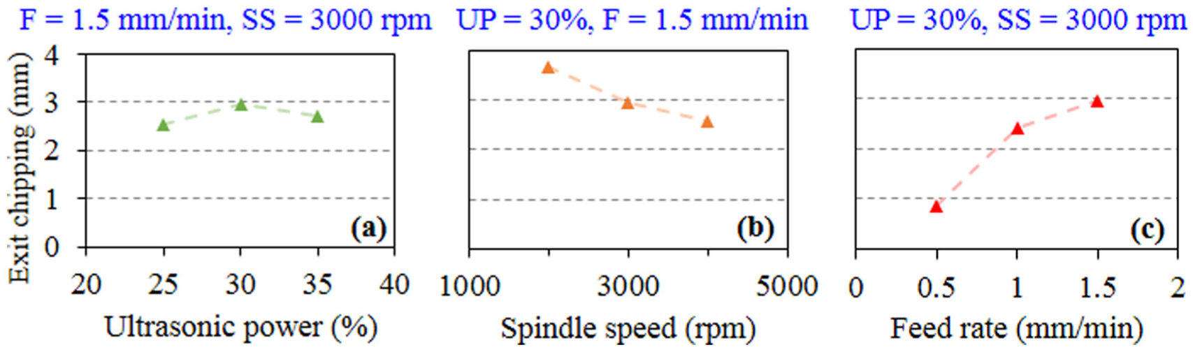
Variation of exit chipping size with RUM input parameters: (a) F = 1.5 mm/min, SS = 3000 r/min; (b) UP = 30%, F = 1.5 mm/min; and (c) UP = 30%, SS = 3000 r/min.
The degree of variation in the surface roughness of the drilled holes with the RUM input parameters is presented in Figure 8. It can be observed in Figure 8(a) that there is a slight decrease in the surface roughness with the increment in the ultrasonic power from 25% to 30% and then there is a slender increase in roughness between ultrasonic power ranges of 30% and 35%. This nonmonotonic and minor effect of ultrasonic power on surface roughness was also observed by Wang et al. 19 It should be commented that the trend of surface roughness with ultrasonic power also depends on the level of the spindle speed selected, and this is presented later in this section. Figure 8(b) shows that the surface roughness increases continuously with the increase in feed rate. In contrast, there is a sharp reduction in the surface roughness as the spindle speed increases as shown in Figure 8(c). This is attributed to the fact that when the spindle speed increases while keeping the ultrasonic power and feed rate constant, the bonded diamond abrasives on the drill are able to cut and scuff the same machined area for longer time, resulting in improved surface roughness, whereas as the feed rate increases, the interaction time of the abrasives with the machined surface is reduced, resulting in deterioration of surface roughness. Moreover, it should be noted that the influence of spindle speed on the surface roughness is found to be considerably more significant when currently RUM is used for drilling BK7 glass compared to when the RUM was used for grinding of BK7 glass by Lv et al. 12

Variation of surface roughness with RUM input parameters: (a) F = 1 mm/min, SS = 3000 r/min; (b) UP = 30%, SS = 3000 r/min; and (c) UP = 30%, F = 1 mm/min.
Figure 9 shows the effect of rotary ultrasonic drilling input parameters on the cylindricity errors of the drilled holes. The cylindricity error increases with the increase in ultrasonic power and feed rate (see Figure 9(a) and (b)). Whereas the cylindricity error reduces as the spindle speed increases as illustrated in Figure 9(c). This might be interpreted with the following reasons: (1) at higher spindle speed and lower feed rate diamond abrasives are engaged with the same surface area for longer time resulting in generation of more uniform cylindrical surface throughout the hole length; (2) as the ultrasonic power increases, the size of cracks induced by the impacts of the ultrasonically vibrating tool also increases 14 leading to increase in the non-uniformity of the amount of materials removed along the cylindrical surface of the holes being drilled. This phenomenon is further augmented at higher feed rates first due to the reduction of the interaction time of the diamond abrasives with the surface being machined thus considerably reducing the tendency of the diamond abrasives to uniformly cut the material from the surface being machined. Second, due to the availability of higher thrust force at higher feed rate to knock out more pre-cracked material from any uneven surface across the hole. For these reasons, it can be noticed that the influence of feed rate on cylindricity is more obtrusive as compared with spindle speed and ultrasonic power.

Variation of hole cylindricity with RUM input parameters: (a) F = 1.5 mm/min, SS = 3000 r/min; (b) UP = 30%, SS = 4000 r/min; and (c) UP = 30%, F = 0.5 mm/min.
Figure 10 shows the variation of overcut error with change in input parameters. Figure 10(a) shows that the size of the overcut remains almost unaffected with the variation in ultrasonic power, while the overcut increases with the increment in both the spindle speed and the feed rate as illustrated in Figure 10(b) and (c). Again, this is accounted to the fact that the increase in spindle speed results in higher interaction time per unit area between the diamond abrasives and the hole surface. This leads to repetitious scratches on the same area resulting in more materials being removed which consequently increase the overcut. Moreover, as the spindle speed increases, the unwanted lateral vibrations of the drill also increase, 19 resulting in increase in the overcut.

Variation of hole overcut size with RUM input parameters: (a) F = 1.5 mm/min, SS = 3000 r/min; (b) UP = 30%, SS = 4000 r/min; and (c) UP = 30%, F = 0.5 mm/min.
Moreover, it should be noted that the diameter of all the drilled holes is found to be greater than the outer diameter of the drill tool (3.97 mm). This is due to the fact that 3.97 mm is a nominal value of the drill diameter, whereas there are diamond abrasives which would be higher than 3.97-mm level and lower as well. This could easily be observed in Figure 11 where an averaged scanned profile measured across the cutting length of a diamond-bonded drill is shown. Once the hole surface is swiped by diamond abrasives which are higher than 3.97-mm level, an overcut is generated. Overcut is further augmented by the level of thrust force available from feed rate and the cracks initiated by the ultrasonic vibrations of the tool.

An averaged scanned profile of a rotary ultrasonic drill measured across the cutting length of the tool.
More experiments were performed to see how the variation in any input parameter can affect the ability of the other input parameters to affect the output responses. Figure 12 shows the effect of varying the spindle speed and feed rate on the influence of the ultrasonic power on the output responses. It can be seen in Figure 12(a) and (b) that the effect of the ultrasonic power on the exit chipping is noticeably affected by variation in the spindle speed and feed rate. For example, at lower spindle speed of 2000 r/min as the ultrasonic power increases, the exit chipping size first decreases and then increases for feed rate of 0.5 and 1.0 mm/min, and on contrary, exit chipping size first increases and then decreases at feed rate of 1.5 mm/min (see Figure 12(a)). However, at higher spindle speed of 4000 r/min, the exit chipping size exhibits a monotonic increasing trend with the increment in ultrasonic power for all the feed rates as shown in Figure 12(b). Hence, higher variations (slope of curve) of exit chipping are observed at higher feed rate (1.5 mm/min) and spindle speed (4000 r/min) as can be seen by comparing Figure 12(a) and (b). This means that the adverse effect of the ultrasonic power on the exit chipping increases at higher feed rates and spindle speeds.

Influence of different levels of spindle speed and feed rate on the effect of ultrasonic power on the exit chipping, surface roughness, and cutting force: (a) spindle speed = 2000 r/min, (b) spindle speed = 4000 r/min, (c) F = 1.0 mm/min, and (d) F = 1.5 mm/min.
Figure 12(c) shows the effect of the ultrasonic power on the surface roughness at different levels of spindle speeds. It can be seen that the variation of the surface roughness changes from continuously increasing at lower spindle speed (2000 r/min) to first decreasing and then increasing at higher values of spindle speeds (3000 and 4000 r/min). Similarly, in case of the cutting force, it can be observed in Figure 12(d) that the cutting force is reduced by 14.71 N when ultrasonic power is changed from UP = 25% to UP = 35% at spindle speed of 2000 r/min. However, the force is only decreased by 8.32 N while the ultrasonic power is varied from UP = 25% to UP = 35% at spindle speed of 4000 r/min. This clearly indicates that the effect of the ultrasonic power on the cutting forces starts diminishing as the spindle speed increases.
The effect of variation of the spindle speed on the influence of the feed rate at different levels of ultrasonic power is demonstrated in Figure 13. With the increment in the level of the spindle speed, the effect of feed rate on the surface roughness starts diminishing, and the slope of the surface roughness curve along with feed rate decreases significantly as shown in Figure 13(a). This is due to the fact that as the spindle speed increases, the plunging effect of the feed rate in the feed direction is reduced as the cutting load is distributed over more number of diamond abrasives.
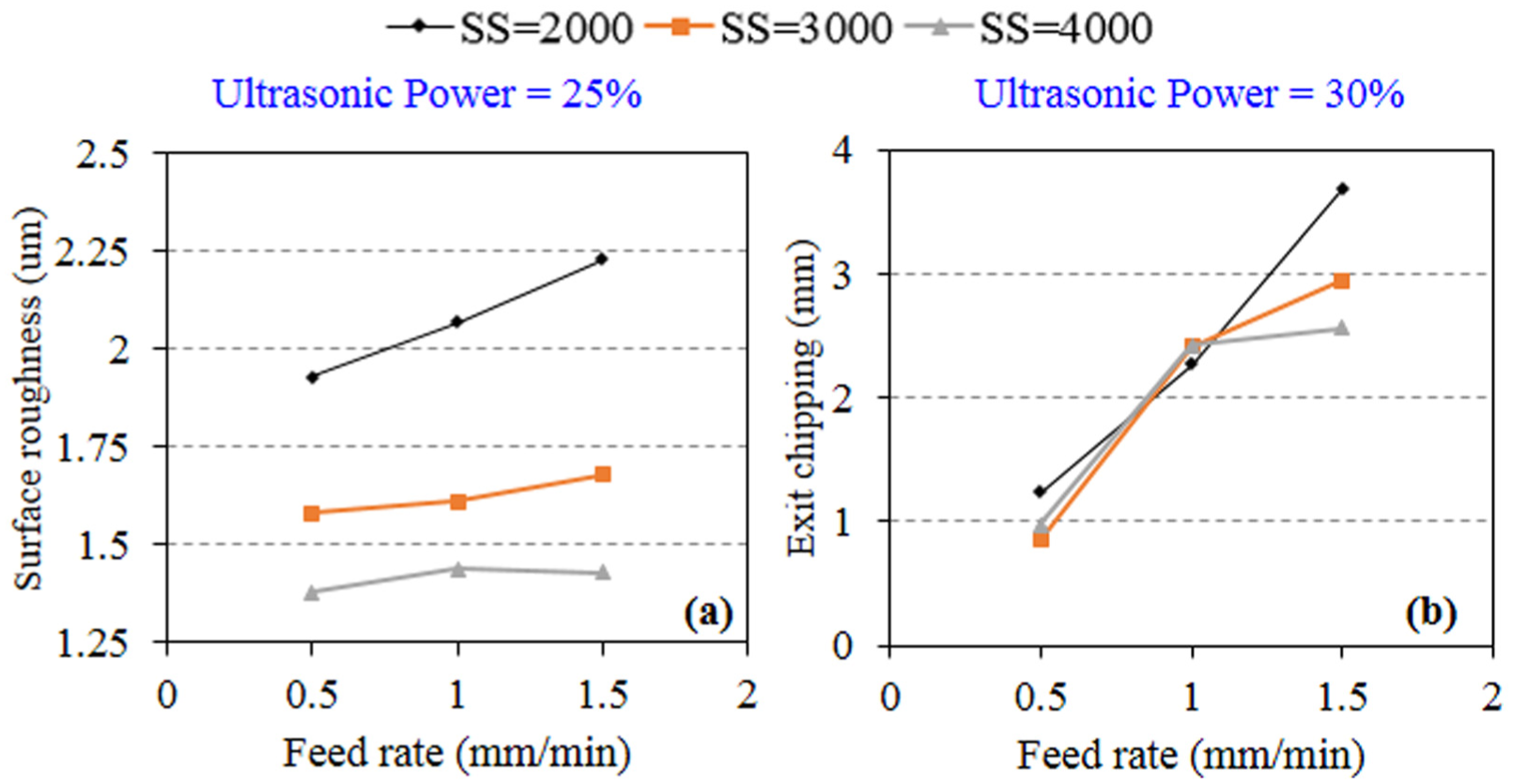
Influence of different levels of spindle speed on the effect of feed rate on the surface roughness and exit chipping: (a) ultrasonic power = 25% and (b) ultrasonic power = 30%.
Figure 13(b) shows that there is no significant influence of varying the levels of the spindle speed on the capability of the feed rate to affect the exit chipping between the range of 0.5 and 1.0 mm/min. However, between the feed rates of 1.0 and 1.5 mm/min, the exit chipping size is considerably reduced with the increment in spindle speed for the same level of the feed rate used. It was found that the ultrasonic power have no significant influence on the ability of the feed rate to affect the output responses. From Figures 12 and 13, it can be commented that in general, the higher spindle speed (4000 r/min) and lower feed rate (0.5 mm/min) and ultrasonic power (25%) would be effective in improving the surface roughness of the drilled holes and reducing the exit chipping size and cutting force.
Figure 14 shows the surface integrity analysis of the rotary ultrasonic drilled holes in BK7 glass. Figure 14(a) and (b) compares the effect of increasing the spindle speed on the surface of the drilled holes. It can be seen that at lower level of the spindle speed (2000 r/min) significantly grooved and fractured topography is produced along with prominent cracks on the machined surface. However, fractured areas are considerably reduced as the spindle speed increases (4000 r/min), and a more uniformly machined surface is produced. This is due to the reason that as the spindle speed increases, the cutting load is distributed over more number of diamond particles, and the depth of cut per particle reduces. This results in lowering the extraction action and increasing the cutting (abrasion) action of the diamond particles on the glass surface. The effect of feed rate on surface integrity can be observed by comparing Figure 14(c) and (d). It can be seen that as the feed rate increases, more fractured areas are generated on the surface. This is owing to the fact that the increase in the feed rate reduces the interaction time between the diamond particles and the workpiece surface. This leads to reduction in the abrasion action and increase in the extraction action of the diamond particles, causing more fracturing on the surface being cut. Figure 14(e) and (f) highlights the influence of the ultrasonic power on the surface of the drilled holes. The fractured areas increase with the increment in the ultrasonic power. This is due to the fact that as the ultrasonic power increases, the hammering action of the tool increases and causes more crack nucleation and propagation in the material resulting in more fractured topography.
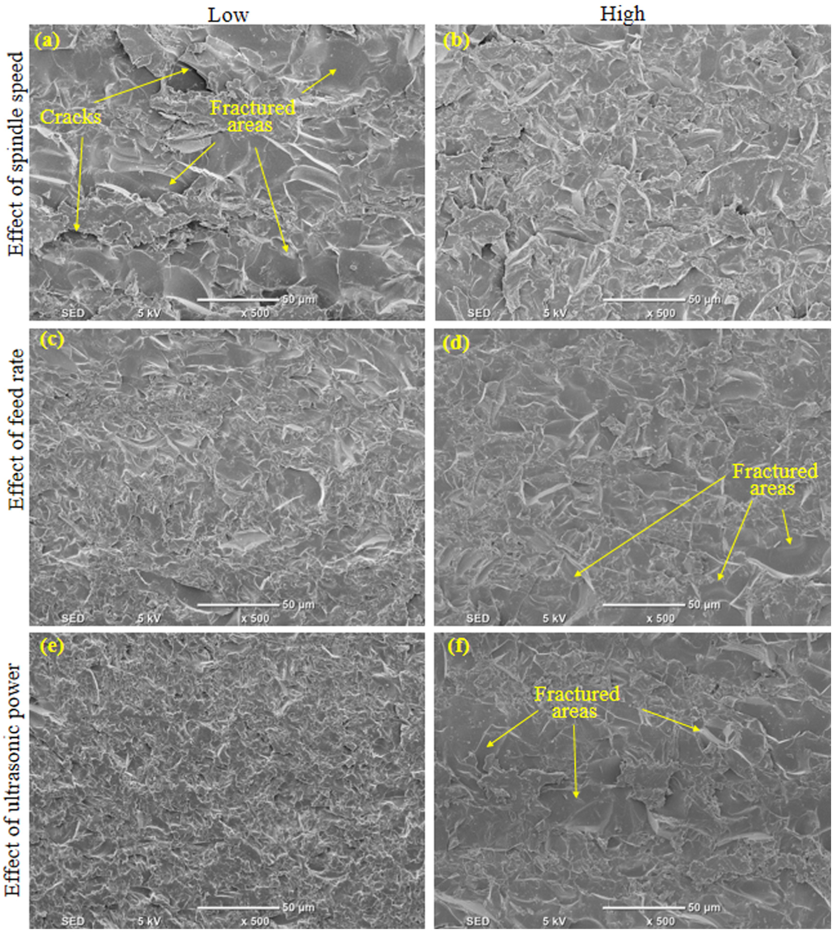
SEM images of the drilled holes: (a) SS = 2000 r/min, UP = 25%, and F = 0.5 mm/min; (b) SS = 4000 r/min, UP = 25%, and F = 0.5 mm/min; (c) SS = 4000 r/min, UP = 30%, and F = 0.5 mm/min; (d) SS = 4000 r/min, UP = 30%, and F = 1 mm/min; (e) SS = 3000 r/min, UP = 25%, and F = 1.5 mm/min; and (f) SS = 3000 r/min, UP = 35%, and F = 1.5 mm/min.
Conclusion
This study experimentally investigates the application of RUM process for drilling BK7 optical glass. The effect of RUM process parameters, including spindle speed, ultrasonic power, and feed rate, is investigated on the output responses of cutting force, exit chipping size, surface roughness, hole cylindricity and overcut, and surface integrity. The following main conclusions can be drawn from this work:
The exit chipping size and cutting force decrease with the increase in the spindle speed and significantly increases with the increment in the feed rate. The effect of ultrasonic power is not well defined on the exit chipping size while the cutting force continuously reduces with the increase in the ultrasonic power. The effect of ultrasonic power on exit chipping size and cutting force is less prominent as compared to spindle speed and feed rate.
The surface roughness of the drilled holes is found to be most substantially affected by spindle speed with higher speeds generating the lower roughness (Ra) values. However, an increase in the feed rate results in increasing the surface roughness, while again there is a nonmonotonic trend of surface roughness with the increase in ultrasonic power from slightly reducing to meagerly increasing.
The cylindricity error is found to continuously increase with the increase in ultrasonic power and feed rate, and it reduces with the increment in the spindle speed, while feed rate being the most influential parameter. The minimum cylindricity error of 3 µm was achieved in this study. In contrast, the overcut error is found to be an inherent characteristic of rotary ultrasonic drilled holes. The minimum overcut error of 73.6 µm was obtained in this work. The overcut error increases with the increase in both the feed rate and the spindle speed.
The scanning electron micrographs reveal that the holes with uniform surface and less fractured topography can be machined by RUM by selecting higher spindle speed, lower level of feed rate, and lower ultrasonic power.
The selected level of the RUM input parameters has the ability to significantly affect the influence of the other input parameters on the output responses.
Footnotes
Acknowledgements
The author would like to acknowledge the support provided by the Deanship of Scientific Research at King Saud University, through the Research Centre at the College of Engineering.
Handling Editor: Min Zhang
Declaration of conflicting interests
The author(s) declared no potential conflicts of interest with respect to the research, authorship, and/or publication of this article.
Funding
The author(s) received no financial support for the research, authorship, and/or publication of this article.