
Abstract
Rotary ultrasonic machining is an excellent method for processing hard brittle materials and has been investigated extensively via theoretical and experimental studies. However, there are few researches about rotary ultrasonic machining of ceramic matrix composite materials. Material removal mode presents both ductile-mode and brittle-fracture when machining hard brittle materials. The ratio of ductile-mode and brittle-fracture has a significant impact on processing status and processing quality. In this article, we developed a cutting force model for rotary ultrasonic face machining of ceramic matrix composite materials. Based on this model, we investigated the effects of cutting parameters on ductile-mode percentage of ceramic matrix composite materials. The cutting depth, feedrate and spindle speed are assumed to be three main factors that affect the ductile-mode percentage in rotary ultrasonic face machining. The primary aim of this article is to verify the correctness of the assumption using a three-variable three-level orthogonal experiment array. The experimental results agreed well with the assumption. The main factors deciding the ductile-mode percentage were found to be cutting depth and feedrate.
Keywords
Introduction
Ceramic matrix composite (CMC) materials are attractive for wide application owing to their superior properties, such as high specific strength, high specific rigidity, high-temperature strength and high wear resistance, such as C/SiC composites. The modulus of elasticity is above 60 GPa. The compressive strength is close to 30 MPa, and the density is only 2000 kg/m3. CMC materials have been increasingly commercialized and used in the aerospace during the last decades. However, CMC materials are nonhomogeneous, anisotropic and extremely hard and thus are difficult to machine, which challenges the manufacturing industry. The main difficulties in machining of CMC materials are low efficiency, high processing cost and unsatisfactory processing quality. 1 Rotary ultrasonic machining (RUM) has achieved good results compared to conventional machining.2–4
In RUM, there exist two modes of material removal: ductile-mode and brittle-fracture mode.5,6 The brittle-fracture mode is explained well by indentation theory, and the material is removed by brittle-fracture. While the material is removed without cracks by ductile-mode, material removal mode significantly affects surface quality and removal rate. The material removal mechanism has been assumed to be brittle-fracture for a long time because a majority of materials processed by RUM are brittle.7–9 After the plastic flow in RUM of ceramics was first observed, 10 a mathematical model was presented to predict the cutting force in ultrasonic drilling based on the ductile-mode mechanism. 5 The ductile percentage in machining of ceramics increases as the spindle speed and the cutting depth increase and also increases as the vibration amplitude decreases. 11 Experiments show that grit size (the diamond size on grinding wheel), amplitude, spindle speed and especially static pressure decide the ductile-mode removal mode. 12 A cutting force model was established on the basis of ductile-mode removal mechanism in ultrasonic vibration–assisted grinding (UVAG) of titanium, and the relation between cutting force and cutting parameters was studied. 13 The effects of grain size, concentration and hardness of the cutting tool on cutting force and tool wear were studied in ultrasonic slot machining of silicon carbide matrix composite. 14 However, the existing literatures focus on ceramic, glass, sapphire and titanium but rarely on rotary ultrasonic face machining (RUFM) of CMC materials or the material removal mode, especially the effects of cutting parameters on the percentage of ductile-mode. Since the angle of impact is random, the ductile-mode and brittle-fracture occur simultaneously. 15 The material removal mode changes from ductile-mode to brittle-fracture with increased cutting depth.16,17 RUM presents two material removal modes in machining. Therefore, it is necessary to study the effects of cutting parameters on the proportion of material removal mode.
In this article, we developed a mechanistic model to predict relationships between cutting force and input variables in RUFM of CMC materials based on indentation fracture mechanics. In this model, the main factors deciding the ductile percentage were proved to be spindle speed (S), cutting depth (ap) and feedrate (f). This conclusion was verified using multi-factor orthogonal test.
Development of cutting force model
Establishment of the model
This article focuses on RUFM. According to Pei et al., 18 RUFM should be a combined process of ultrasonic machining and diamond grinding, including three material removal mechanisms: hammering, abrasion and extraction (Figure 1). Therefore, a conic tool was used as a cutting tool (Figure 2). Vibration is in the longitudinal direction.
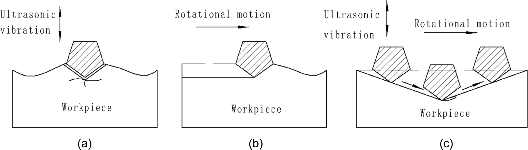
The three material removal mechanisms: (a) hammering, (b) abrasion and (c) extraction.
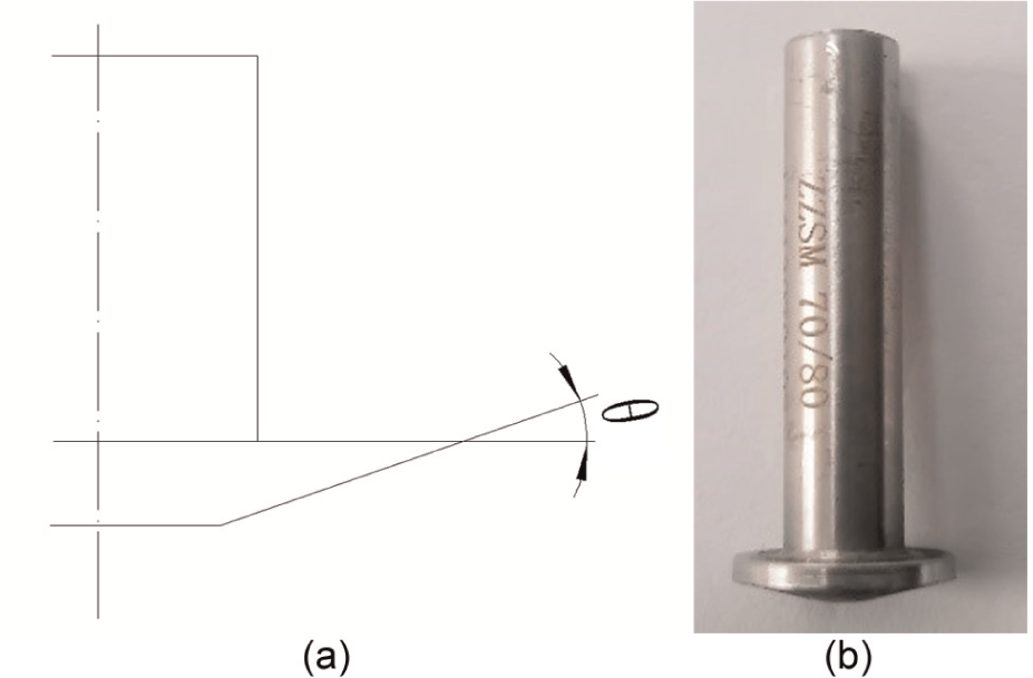
Conic tool: (a) Tool Design; (b) Milling tool.
Based on indentation fracture theory,19,20 there is a deformation zone in the contact region (Figure 3). In this mechanism model, we assume that the maximum penetration depth (the maximum depth of the diamond abrasive grains penetrate into the workpiece during the ultrasonic vibration) does not reach the critical level and only consider the plastic deformation zone, ignoring the median crack and lateral crack. The material removal mode is rigid ductile-mode.
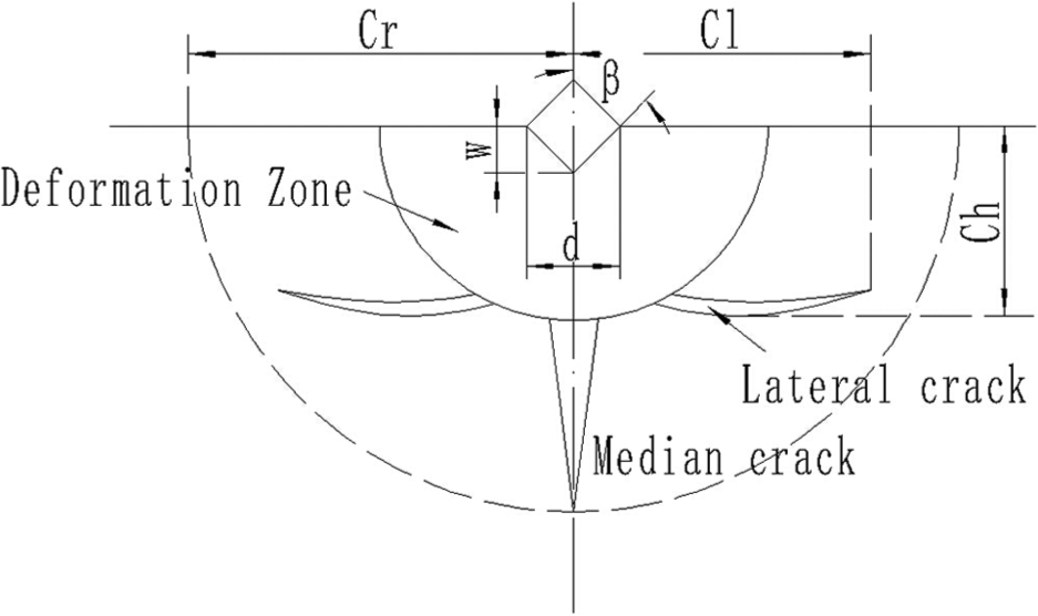
Crack generation and plastic deformation zone in brittle material.
The maximum penetration depth was used as an intermediate parameter to establish the relationships between the input parameters (spindle speed, feedrate and cutting depth) and the output parameter (cutting force). There are three assumptions or simplifications:
Material removal mode is rigid ductile-mode;
All the diamond abrasive particles are of the same size;
The diamond abrasive particles are rigid octahedrons.
Relationship between maximum penetration depth and cutting force
Normal force (Fn, perpendicular to the machined surface) can be expressed as 21

where
Relation between normal force and contact area.
According to the geometric relationship, the abrasive particle which is a regular octahedron can be expressed as follows

where w is the maximum penetration depth, Sa is the side length of the regular octahedron, β is the semi-angle and L is the side length at w (Figure 5).
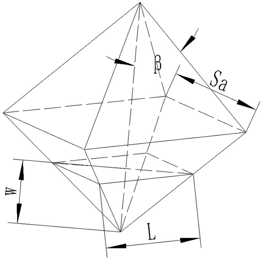
Octahedron abrasive particle.
From equation (2), then

Substituting equation (3) into equation (1), then

The relation between Z and f can be obtained (Figure 6)

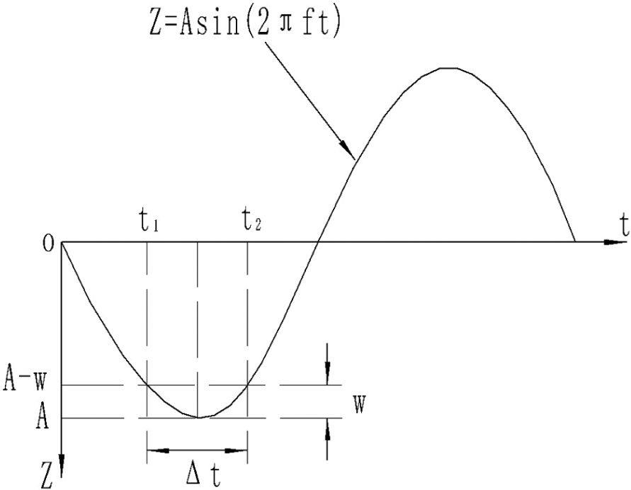
Relation between effective contact time Δt and maximum penetration depth (w).
where Z is the trajectory of the diamond abrasive grains, A is the amplitude, f is the frequency and t is time.
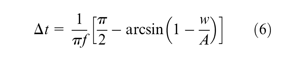
According to equation (5) and Figure 6, effective contact time Δt can be expressed as follows
Based on the energy conservation theorem, then
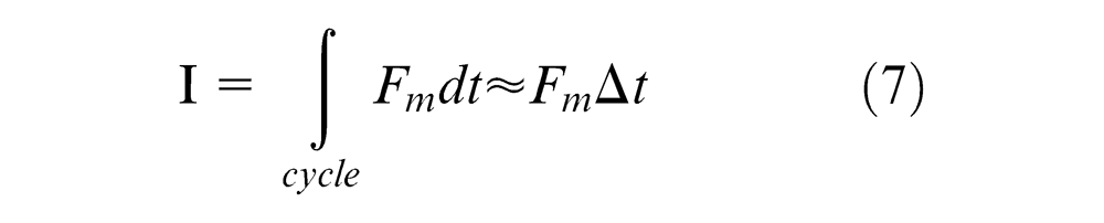

where I is the impulse, Fm is the maximum impact force, Δt is the effective contact time during which an abrasive penetrates into the workpiece, cycle is a vibration cycle of the diamond abrasive grains and Fr is the cutting force caused by single diamond abrasive

Figure 7 illustrates the geometrical relationship of the cutting force F, which can be expressed as follows
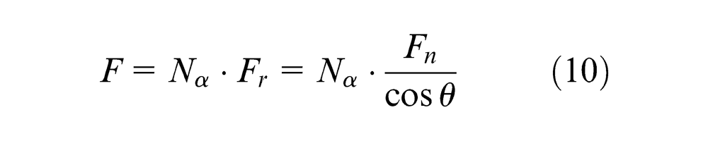
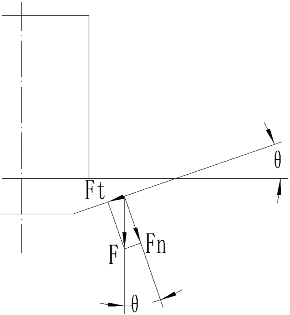
Relationship of cutting force.
where F is the cutting force caused by all the active diamond abrasives, and it is the resultant force of Fn and Ft; Fn is the normal force and Ft is the tangential force.
Substituting equation (6) into equation (9), then
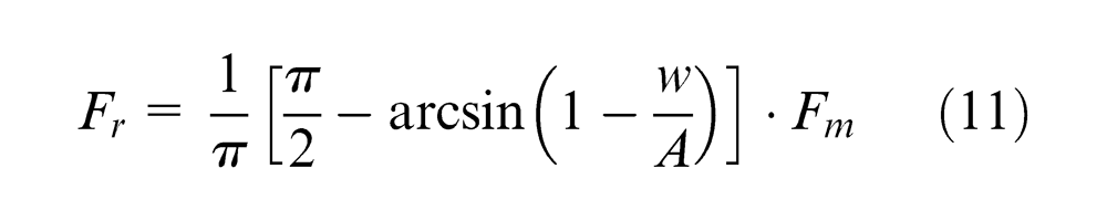
Substituting equation (11) into equation (10), then
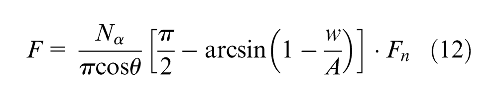
where N α is the summary number of active abrasives during machining.
Based on the definition of abrasive concentration, N α can be computed as follows 9

where C α is the concentration of the abrasive, A0 is the contact area of the conic tool and workpiece and C1 is a constant number, C1 = 0.030414.
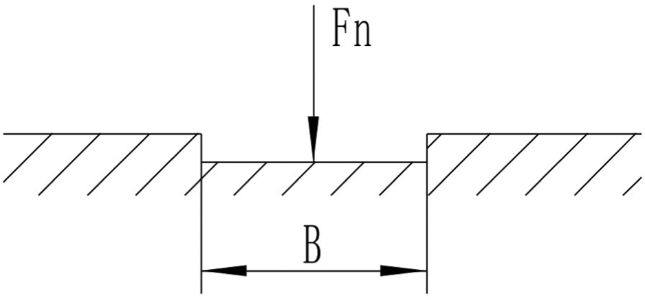
Figure 8 shows the relationship of contact area and geometry of conic tool. Whether the cutting width bD is larger or smaller than R1, the A0 can be calculated as follows
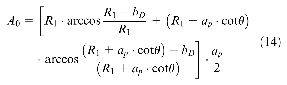
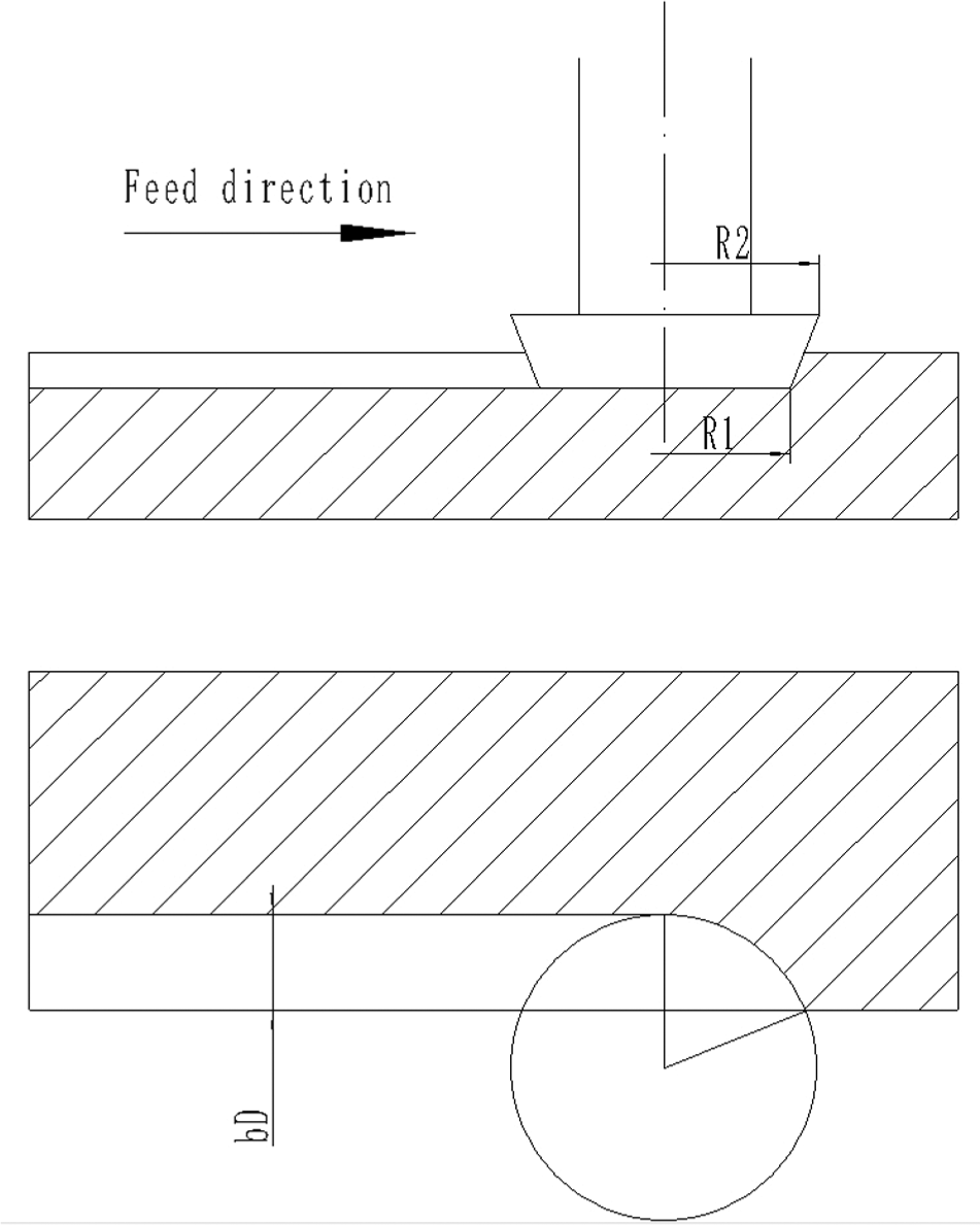
Calculation of contact area (A0).
where R1 is the smaller radius of the conic tool, R2 is the larger radius and ap is the cutting depth.
Substituting equation (4) into equation (12), the relationship between the maximum penetration depth and the cutting force can be expressed as follows
Relationship between maximum penetration depth and cutting parameters
Figure 9 illustrates the material removal volume as the abrasive particle penetrates into the workpiece. The penetration depth increases from 0 to w first and then decreases to 0 within
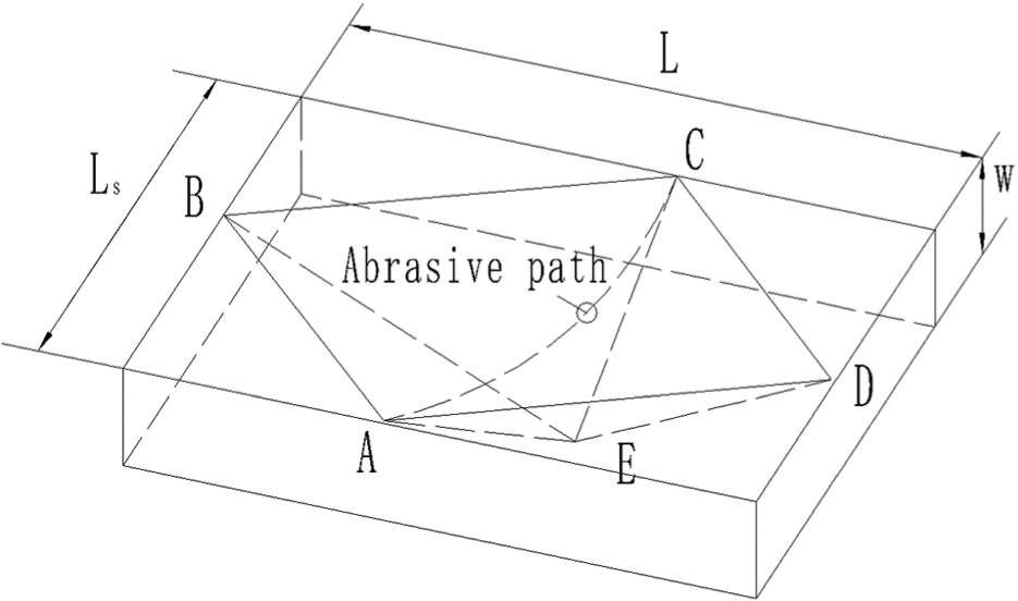
Calculation of material removal volume.
where Ls is the length when the abrasive particle moves within one period

where S is the spindle speed (r/min) and R is the distance from the abrasive particle to the conic tool’s center (mm).
Substituting equations (3) and (17) into equation (16), then
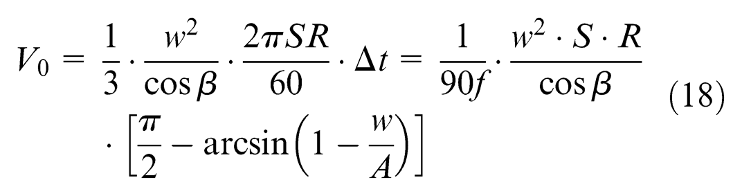
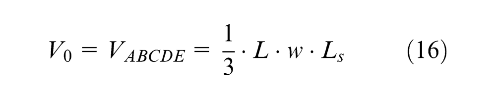
The material removal volume (V) within one penetration period is nearly equal to the volume of theoretical material removal volume (V0). We assume V and V0 are in linear proportion, then 9

where k is a constant and can be obtained from cutting force experiments.
MRRa is the material removal rate of single diamond abrasive. Since V is the material removal volume caused by single diamond abrasive in one vibration, MRRa can be expressed as follows

Material removal rate MRRT is the summary of the material removed by all the effective abrasive particles during one period and can be expressed as follows
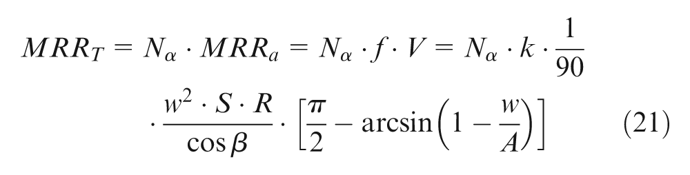
For simplification, average radius

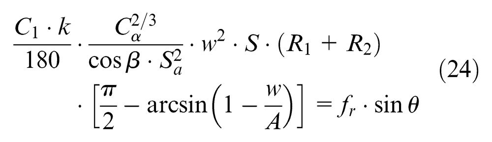
MRRT can also be expressed as the volume swept by the conic tool during one period

By solving both equations (22) and (23), the relationship between maximum penetration depth and cutting parameters can be obtained as follows
Cutting force model
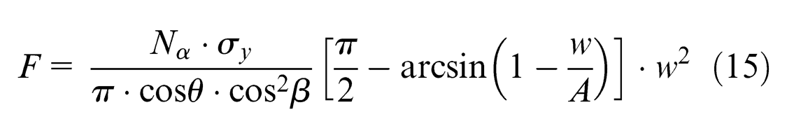
By solving both equations (14) and (24), the relationship between cutting force and cutting parameters can be obtained as follows
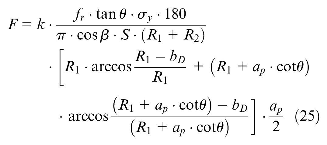
The following conclusions can be obtained from equation (25): the cutting force was improved with the increase in the cutting depth (Figure 10(a)) and feedrate (Figure 10(b)) but decreased with the increase in the spindle speed (Figure 10(c)). It can be assumed from the existing experiment that the percentage of ductile-mode increased with the decrease in the cutting force. 11 Thus, the ductile-mode percentage increases with the increase in the spindle speed but decreases with the increase in the cutting depth and feedrate.
Influence of cutting parameters on cutting force (simulation): (a) cutting depth, (b) feedrate and (c) spindle speed.
Experimental verification
The cutting experiments are carried out, and the main purpose of cutting experiments is to verify the effects of cutting parameters on ductile-mode percentage.
Experimental setup and conditions
The experimental apparatus is schematically illustrated in Figure 11. The experiments are performed on a DMG ultrasonic linear 20. The experimental setup is composed of three parts: ultrasonic vibration system, conic tool and 5-axis milling machine. The ultrasonic vibration system consists of ultrasonic spindle and an ultrasonic generator.
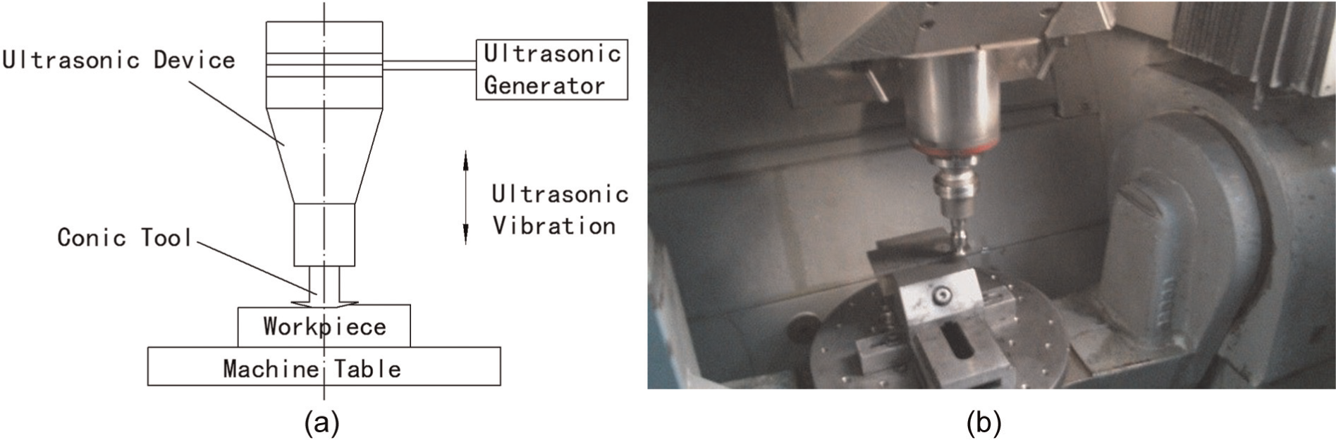
Experimental apparatus: (a) Ultrasonic machining system; (b) RUFM of C/SiC on Ultrasonic liner 20.
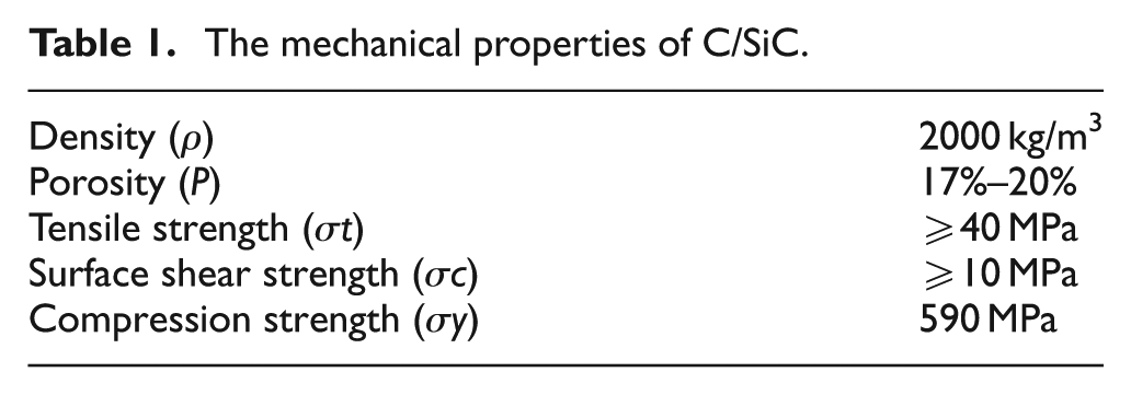
The workpiece is made of C/SiC composite. The mechanical properties are shown in Table 1. The sample is manufactured according to the following process:
The mechanical properties of C/SiC.
Two-dimensional carbon fiber weave → vapor deposition (2–3 weeks) → liquid phase deposition and carbonization (4–6 weeks) → the middle temperature purification process → rough machining → liquid phase deposition (about 2 weeks) and carbonization → high-temperature purification process → siliconized (2–4 weeks) → precision machining → finished.
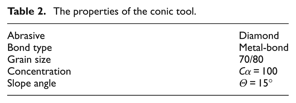
The properties of the conic tool are shown in Table 2. The experimental design is shown in Table 4. The experiments involve three groups of input parameters (spindle speed, feedrate and cutting depth). The cutting parameter is designed by orthogonal experiment array with three factors at three levels. In order to analyze the effect of errors on the experimental results, there is a blank column as error.
The properties of the conic tool.
Measurement of ductile-mode percentage
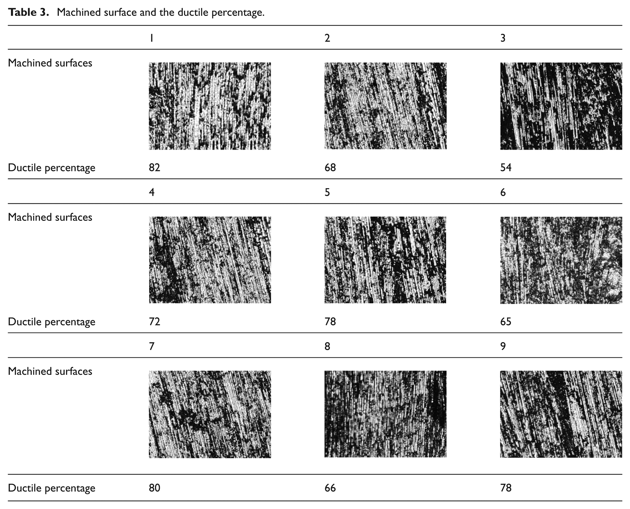
The surface topography of the workpiece was photographed by an Xtl-2400 microscope (Shanghai Caikon Instrument Co., Ltd.) at zoom multiple of 300×. Under the material removal mechanism of ductile-mode, the fibers were clear and continuous (Figure 12, white region), but under the brittle-fracture mode, the fibers were broken with some pits on the surface (Figure 12, black region). The ductile-mode region is magnified using scanning electron microscope (SEM; SSX-550, SHIMADZU), shown in Figure 13. The brittle-fracture mode region is shown in Figure 14. The proportion of white areas is measured by measurement software supporting the Xtl-2400 microscope. The cutting force is measured by dynamometer (9257B, Kistler). The results of the machined surface and the ductile percentage and cutting force are shown in Table 3.
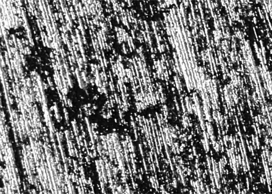
Machined surfaces with ductile-mode percentage (80%).
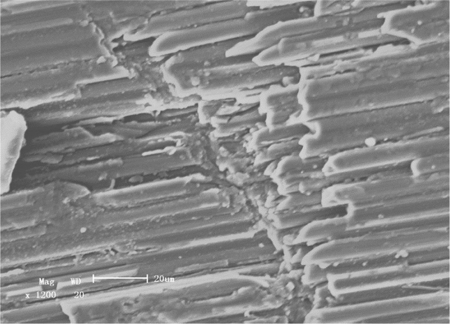
Ductile-mode region (1200×).
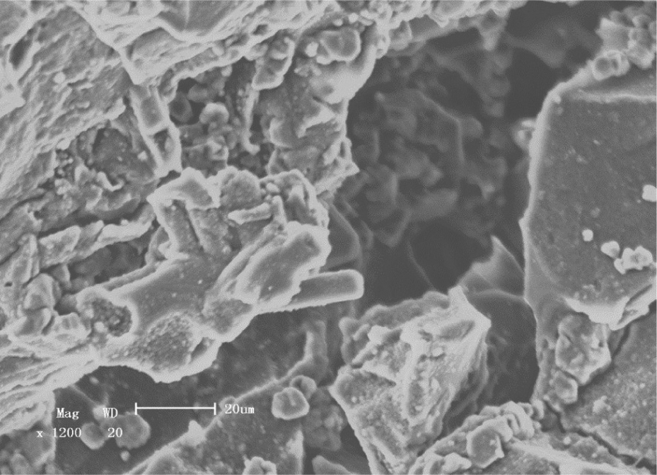
Brittle-fracture region (1200×).
Machined surface and the ductile percentage.
Experimental results and discussion
The experimental results are listed in Table 4. The results indicate that the factors significantly affecting the cutting force were the cutting depth and feedrate. The effect of experimental error is only 2 and can be ignored.
Intuitionistic analysis.
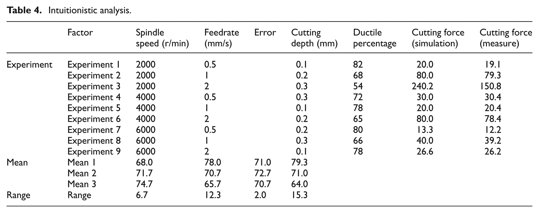
The measured values and simulated values (k = 2) of cutting force are almost consistent except experiment 2. This may due to the high proportion of brittle-fracture and cannot be ignored in experiment 2. Thus, the cutting force must be the synthesis of ductile-mode and brittle-fracture. In this article, the influence of ductile-mode percentage on the surface quality is the main research, and most of the simulation results agree well with the experimental results, so the cutting force caused by brittle-fracture is ignored in this article.
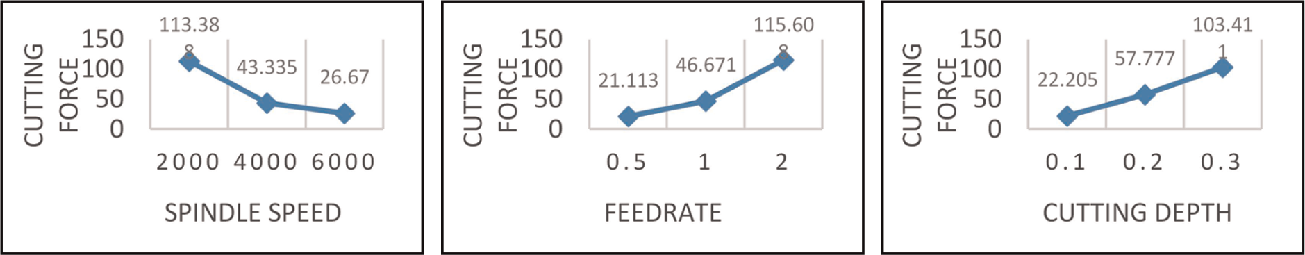
The effect curves indicate that the cutting force increases with the increasing cutting depth and feedrate but decreases with the rising spindle speed (Figure 15), while the ductile-mode percentage is opposite (Figure 16), which are consistent with the theoretical analysis. Thus, the theoretical model is accurate.
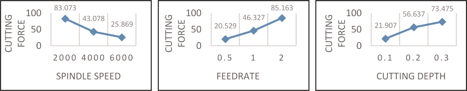
Effect curves (cutting force): (a) spindle speed, (b) feedrate and (c) cutting depth.
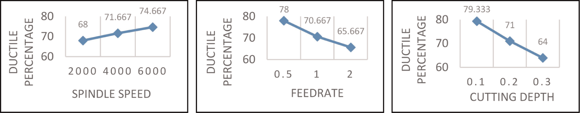
Effect curves (ductile percentage): (a) spindle speed, (b) feedrate and (c) cutting depth.
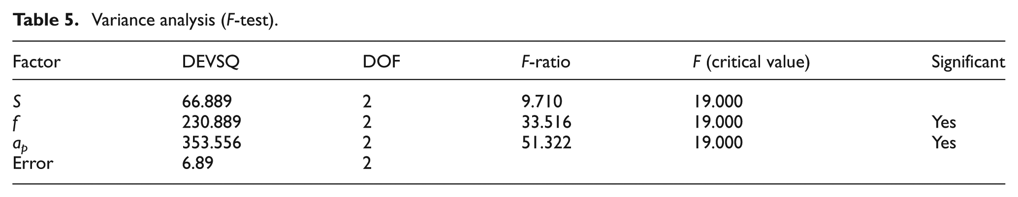
The significance of each factor was tested at level A = 0.05. Table 5 shows that Fap > Ff > F (critical value) > FS, indicating that the ductile-mode percentage was affected most significantly by the cutting depth, followed by feedrate but not significantly by the spindle speed. The reason might be that the cutting depth and feedrate should be controlled more stringently so as to further improve the ductile-mode percentage after it reaches a certain value. Since orthogonal experiment array does not select all the combinations of parameters, in this set of experiments, the combination of cutting depth and feedrate might limit the effect of spindle speed on the increase of the ductile-mode percentage. Moreover, despite the effect from the cutting force, the ductile-mode percentage is more directly affected by the maximum penetration depth. Therefore, it is necessary to establish a maximum penetration depth model for further research. Based on this model, we can analyze the effects of different cutting parameters on ductile-mode percentage. In Table 5, DEVSQ is sum of squares of deviations from the mean, and DOF is degree of freedom.
Variance analysis (F-test).
Conclusion
We developed a cutting force model for RUFM of CMC materials based on the ductile-mode removal mechanism. Based on this model, the effects of cutting parameters on ductile-mode percentage were studied. Major conclusions are as follows:
Ductile-mode percentage decreases with the increase in the cutting depth or feedrate but increases with the increase in the spindle speed. The ductile-mode percentage is affected most significantly by cutting depth, followed by feedrate and then rotational speed.
Lower cutting depth and higher feedrate can be used in RUFM of CMC materials to obtain higher surface quality and processing efficiency.
Despite the effect from the cutting force, the ductile-mode percentage is more directly affected by the maximum penetration depth. Therefore, it is necessary to establish a maximum penetration depth model for further research.
RUFM can effectively reduce the fracture of carbon fiber and improve the surface quality (Figure 17).
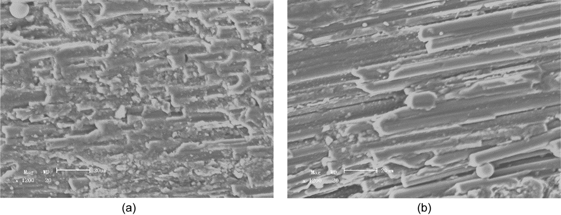
Machined surface: (a) conventional milling and (b) RUFM.
Footnotes
Declaration of conflicting interests
The authors declare that there is no conflict of interest.
Funding
This work was supported by National High Technology Research and Development Program of China (863 Program) (2013AA040105) and Basic Scientific Research Program of China.