
Abstract
Real-time nonlinear error caused by rotation axis motion in five-axis interpolation can be compensated by rotational tool center point function. It is well known that reduction of the interpolation nonlinear error can be achieved effectively by increasing the interpolation steps, but what the value of the steps’ number should be has rarely been mentioned in the existing literature. Taking a five-axis interpolation machine tool with B & C swing axis as an example, the real-time planning and controlling for the integrated feed rate of a five-axis interpolation is proposed by analyzing mechanism of the nonlinear error in the interpolation with rotational tool center point function. The nonlinear error and its derivative of the swing axis are derived. Then, a S-shape feed rate real-time planning and control method about curve interpolation is present first, and then considering the restrictions of the tool axis motion by the feed axis’ mechanical properties and the cutting characteristics, the most appropriate interpolation step length in a single interpolation cycle is calculated in real-time. It shows that comparing to approach with no rotational tool center point interpolation error control, the interpolation error acquired by rotational tool center point in proposed approach can be further reduced while ensuring the smooth and safe machining of the machine tool, and the surface quality of workpiece is also greatly improved.
Keywords
Introduction
In the aerospace, automobile manufacturing, and other fields, for engine blade workpieces formed by free-form surface processing, the use of five-axis computer numerical control (CNC) machining is an effective way to improve the processing efficiency and accuracy. When NC machining programming for this kind of parts, the curved path is discrete approximation of a series of small straight line segments. These line segments are the theory paths of the tool center point programming. Therefore, in actual machining, in order to ensure the accuracy of the program effectively, the linear interpolation of actual tool center path should be in accordance with the micro-segments strictly. In five-axis linkage machining, there are two more rotational axes than that in general three-axis machine tool, so the control of tool position and direction is more flexible, and the tool can be kept in the optimum cutting conditions. But because of the rotational movement, one or more rotating axis movement will cause translational movement of the tool center; the synthetic linear motion of all feed axes will likely make the interpolation path of the tool center point seriously deviate from the original programming micro-segment in a line, thus result in interpolation nonlinear error.2,3 Currently, the approaches to nonlinear error control are mainly two. One method is to take the specific structure of five-axis machine tools parameters such as the rotating shaft center distance (the distance from tool cutting center to rotation shaft center) as the basis and use the special post-processing program to convert the original programming cutter location file (CLF) to machining file. In actual machining, the structure parameter such as rotating shaft center distance must be consistent with the values entered in the post-processing; otherwise, the machining path will be seriously deviated from the program path. Also for the same parts, once machine tool or machining tool has changed, or machining tool has been abraded, a new post-processing should be executed according to the new rotating shaft center distance, and it will bring greater inconvenience to the NC programming. Another method is to integrate rotational tool center point (RTCP) or rotational around part center point (RPCP) programming function directly in the NC system, which could compensate in real-time coordinates changing of translational axes due to tool rotation or workpiece rotation in the interpolation process. Therefore, it does not need to be concerned with rotating shaft center distance during designing and programming, but inputting the actual value directly during machining to compensate the real-time error, which will enhance the applicability of five-axis machining program.
For RTCP or RPCP research, it mainly focused on motion compensation algorithm for coordinate transformation and interpolation error analysis, but less on speed control algorithm by combination of five-axis interpolation. Fan and Yang 4 analyzed theoretical processing error between the actual path and the nonlinear continuous space path in five-axis CNC system with linear interpolation movement, established motion conversion mathematical model of a five-axis machine tool with double turntables, and then established estimation model of nonlinear motion error in these kind of five-axis machine tools. Hang et al. 5 introduced an interpolation algorithm with integrated RTCP function which is based on in-depth analysis on double turntables movement principle of five-axis machine tool and simulated it in MATLAB. The results indicated that the algorithm could effectively reduce the nonlinearity error, but it did not elaborate that how to maximize the feed rate based on the machining accuracy. Remus and Feng 3 calculated the geometric errors caused by linear interpolation through the movement of machine. Fan et al. 6 derived a mathematical formula of RTCP or RPCP in five-axis CNC system based on the analysis of the RTCP function and developed a simulation software based on OpenGL to simulate the formula. Zhao et al. 7 designed an integrated interpolation algorithm of RTCP function and presented the theoretical error and the simulation results. Yang et al. 8 proposed a method to control machining nonlinearity error by restricting the angle between two adjacent cutter locations and estimated the relationship between the maximum nonlinear error and the angle increment of cutter locations, but did not consider the restrictions of the machine’s movement ability and the machining characteristics on interpolation tool location angle increment. He et al., 9 Lin et al., 10 Liu et al., 11 Wang et al., 12 Ye and Wang, 13 and Li et al. 14 proposed a speed pretreatment method according to the machine kinematics constraints which calculated the maximum feed rate to meet the mechanical and path characteristics of the machine, but it only considered the consistent feed rate between drive axis and tool tip in three-axis CNC machining and therefore could not be directly applied to the five-axis CNC system. Lavernhe et al. 15 dealt with a predictive model of kinematical performance in five-axis milling within the context of high-speed machining and proposed that the calculation of the tool feed rate could be performed and the feed rate has no highlighting zones. There certainly exists the interpolation nonlinear error in five-axis interpolation because of the axis rotation and complex relationship between interpolation path and movement of each axis. Limiting interpolation step length is effective to reduce the interpolation nonlinear error. An excessive limitation would often cause the sharp decrease of the processing efficiency; however, an inadequate limitation would cause larger interpolation nonlinear error and might be exceed the allowed range of motion capability of the machine tool and machining characteristics. Therefore, real-time planning of five-axis interpolation step with RTCP or RPCP function is the key to achieve machining of high efficiency, high precision, and high stability.
Five-axis CNC machine tools have a variety of configurations according to the structure. At present, the most common is a combination of the three translational axes and two rotary axes. Combination of three translational and two rotating axes from the machine tool structure design can be divided into three categories: (1) double swing structure, that is, two tool axes rotate; (2) double turntables structure, that is, two turntables rotate; and (3) a swing and a turntable structure, that is, a tool rotating shaft and a turntable. Rotation axis A, B, C, respectively, revolves around the axes X, Y, Z. The double swing machine tool is very flexible and can realize processing without blind spots, thus can meet the processing requirements of large-scale three-dimensional modeling, engine shell, and other complex parts. 16 Taking the multi-axis B & C double swing interpolation machine tool for example, fully considering the speed and acceleration of the drive axes of machine and other mechanical properties and machining characteristics of the tool center, a planning control method for the integrated five-axis feed rate on the basis of analysis of interpolation nonlinear error with RTCP function is proposed in this article.
RTCP function realization and kinematics coordinate transformation of a five-axis system with B & C double swing
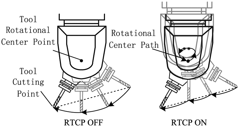
As shown in Figure 1, when applying the RTCP function, NC machining code is the tool center point information but not the motion position coordinates of the rotational tool center. Tool center point information includes tool position coordinates (indicating the coordinate position of the cutting point) and the tool axis vector (indicating the deflection direction of tool shaft on the cutting point). During interpolation process, NC system is in accordance with the principle of linear interpolation, calculate the tool center point coordinates in every interpolation cycle and the corresponding tool axis vector according to the interpolation nonlinear error, feed rate, and other parameters. And then the tool center point coordinates and the tool axis vector will be converted to the position coordinates of rotational tool center and the rotating shaft center distance. Thus, the system will control the translational and rotational of the tool center. Path bias brought by every movement of rotation axis will be compensated by one linear displacement of X, Y and Z axes, and finally each of interpolation end points is in the original designed programming path of the tool center.17–19 It is not necessary to consider the rotating shaft center distance during NC programming. Even the rotating shaft center distance changes due to the replacement of machine or the cutting tool’s change or tool wear, as long as the correct value is input while processing, the system can still ensure that the interpolation points are always located in the programming track, and it is unnecessary to regenerate the processing code every time once the rotating shaft center distance is changed. Therefore, the auxiliary machining time will be greatly reduced, and the machining efficiency and the geometric precision of workpiece will be greatly improved. In addition, the programming speed which is actually controlled with RTCP function is relative to the tool center point; therefore, the surface quality of the workpiece can be better controlled according to the processing conditions, and the tool life can be extended. But in the multi-axis interpolation with RTCP function, the interpolation nonlinear error must be controlled at all times and the feed rate must be integrated planning; otherwise, it is very easy to cause the machining jitter and to reduce the surface quality of workpiece.
Tool-swing programming based on RTCP.
In the processing code generated by the five-axis Computer Aided Manufacturing (CAM) software, the workpiece coordinate

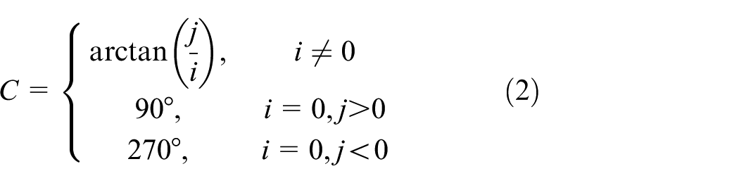

Swing angle calculation in double swing machine tool.
Generalized resultant feed rate for multi-axis machining
Generation of the interpolation nonlinear error with the motion of rotation axis
Planning path and actual machining path of the deviation of tool axis angle
In the five-axis NC machining system, interpolation is carried out according to the geometric information of the parts while the linear interpolation of the tool axis vector is used generally in tool path planning stage. Using this interpolation method, when interpolation of vector approaches the singular point area of the machine tool, rotating shaft will discontinuously and rapidly rotate, and machine can easily lead to severe vibration and cannot meet the smooth motion and performance constraints for axis. Thus, in actual processing, to the different structures of the machine tool, tool axis moves generally according to the linear interpolation of rotation axis. Taking the B & C double swing five-axis NC end milling as an example, the corresponding tool axis vector motion path of the two interpolation methods are analyzed.
As shown in Figure 3(a),

where


Axis locations movement in five-axis NC machining: (a) axis locations movement with linear interpolation method of the corresponding rotation axis and (b) axis locations movement with linear interpolation of the tool axis vector.
When the tool path planning is carried out in CAM system, the information of the machine tool is not known in advance, so the tool path is calculated by the linear interpolation of the tool axis vector.
20
That is to say, the tool axis rotates from
As shown in Figure 3(b), the angle between ne and n0 is tθ (t = 0–1). Let n2 is a tool axis vector that is perpendicular to n0 and
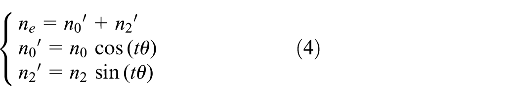
Then

In the same way,

Equation (6) can be written as
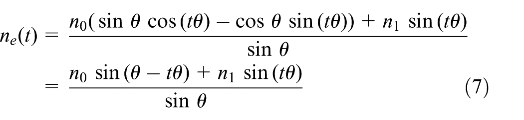
Comparing the two formulas above, it shows that the tool axis vectors of other arbitrary moment t except the first and end point are not consistent during the interpolation process, and the principle processing error due to the change of the way of interpolation will be inevitably brought. The deviation angle of two tool axes at any time t is

The maximum deviation angle of the tool axis has been estimated in Yang et al. 8 as above
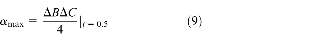
For side milling, the machining error caused by the deviation angle α of the tool axis is

where h is the machining depth.
The allowed value of nonlinear error caused by rotating axis is [ε]. Combining equations (9) and (10), the rotation angle of axes B and C must meet

In an interpolation line, all axes including rotating axes meet the linear interpolation relationship during processing;
Interpolation nonlinear error with RTCP
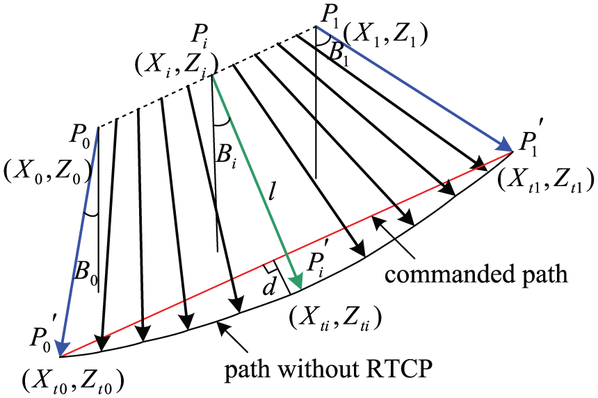
For better illustrating the RTCP function (only X, Z axes translational and B axis swinging), the tool axis movement only in XZ plane is taken as an example. To five-axis interpolation that has translational motion of X, Y and Z axes and double swing motion of B & C, the error analysis method can be further derived based on this algorithm. As shown in Figure 4, the tool coordinate is represented in
Linear interpolation process without RTCP function.
For the linear interpolation without RTCP function, the swing center path is always on the line segment

where
The tool center coordinates on starting and ending points in required interpolation segment
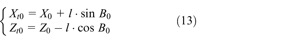

Therefore, the distance between any point on tool center path to the interpolation segment

where
where

Linear interpolation process with RTCP function.
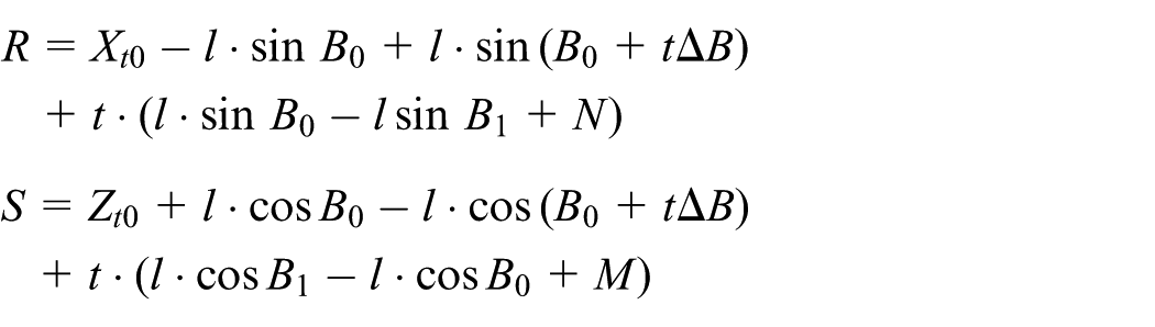
Interpolation tool center at the beginning of one interpolation cycle in RTCP is the end point of the last interpolation cycle. The point coordinate relates to the
Supposing

Nonlinear error curve of different interpolation segments: (a) nonlinear error with 1 interpolation segment, (b) nonlinear error with 50 interpolation segments, (c) nonlinear error with 100 interpolation segments, and (d) nonlinear error with 200 interpolation segments.
In real-time interpolation, the interpolation accuracy is mainly determined by the maximum interpolation nonlinear error. Because

For a specific interpolation, M, N,
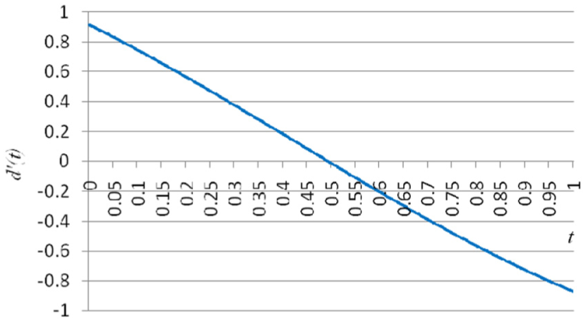
As shown in equation (17) and Figure 7, maximum nonlinear error is unrelated to tool length, and at the point
If the interpolation step length is fixed, the influence of tool length change on the nonlinear error is shown in Figure 8. It can be seen that the nonlinear error increases with the increase of the tool length and is proportional to the latter. Therefore, if the tool length changed due to tool changing or wearing, the interpolation step length should be reduced or increased to meet the preset interpolation precision.

Nonlinear error curve of different tool lengths.
Constraint condition of interpolation step length with RTCP function
In five-axis machining, either tool rotation or swing center is driven to translate and rotate by CNC system in interpolation of every cycle, thus completes the tool center interpolation. Under certain interpolation parameters, the movement of rotation center and tool center are closely related. The parameters such as movement speed and acceleration of the rotation or swing center are related to the mechanical characteristics and electrical characteristics of the system. To a specific machine tool, it has the maximum driving force. The cutting process is completed by tool center movement, as a result the cutting speed is limited by the machining characteristics of the machine tool because of the difference of the workpiece material, cutting tool material, and cutting parameters. Therefore, for RTCP function interpolation, the interpolation step length of every cycle is affected synthetically by the nonlinear error, the machine tool motion capability, and the machining characteristics. Based on the control strategies of acceleration, deceleration, and velocity look-ahead, the interpolation step length
Constraint condition of interpolation nonlinear error with RTCP function
Under processing conditions of multi-axis linkage with rotation axis or swing axis, while the structural parameters of the machine tool are determined based on the RTCP function interpolation, for a multi-axis interpolation path, the cutter location parameters have been identified. Supposing the allowed processing error is
Supposing the tool location has reached coordinate
Under this constraint condition, the maximum micro interpolation increment
Constraint condition of cutting speed of the tool center point
Cutting parameters are selected by considering not only the machined material, machining accuracy, and surface roughness requirements, but also processing conditions such as tool durability and machine system rigidity. The cutting speed is the main factor of cutting parameters. With the certain processing conditions, the machining is required to control its maximum feed rate. In the micro interpolation process, the nonlinear error brought by swing axis motion has to be controlled in very small range, and the actual interpolation path length is very close to the programmed micro-line segment path length; thus, the effect of the swing axis motion on the cutting speed can be ignored, and the cutting maximum feed rate is mainly limited in the maximum velocity of translational axis. Supposing the required maximum cutting feed rate of the tool center point is

The interpolation step length is X and Z axes motion synthesis; therefore, under this constraint condition, the interpolation step length of every axis of tool center is
Constraint condition of rotating speed of the tool swing center
For multi-axis NC system with swing axis, it drives tool swing center to translate and rotate directly, so as to complete the corresponding machining path of tool center point. The swing center has both linear and rotary motion. Due to the existence of tool bar, the tool center path does not synchronize the tool swing center path. As shown in Figure 9, in a five-axis interpolation with RTCP function, tool center motion and rotary center motion influence each other. Under extreme cases such as rapidly turning point in interpolation, small change of the tool center point will lead to large overall motion of linear axis or rotation axis, the motion velocity tends to be more than allowed value of machine tool; thus, it is easy to cause reducing of the machining accuracy or even workpiece being scrapped. Therefore, the feed rate must be judged and limited in the interpolation algorithm to ensure the smooth and safe cutting.

Rotational center movement influenced by tool center movement.
Considering the processing load, motor overload capacity, and other factors, every linear axis has the maximum permissible displacement speed, and the swing axis also has the maximum allowed swing angular speed. Although the machining path is path synthesis of every axis linkage motion, it can be decomposed into the independent movement of every axis. The axle load capacities generally vary for a specific machine tool, so the maximal axle velocity tends to be different. Still taking the interpolation path for example, the allowed maximum velocity of X and Z axes are

Taking into account all the above-mentioned constraints of the interpolation step length of the tool center, according to equation (12), under this constraint condition the interpolation step length of the tool center is

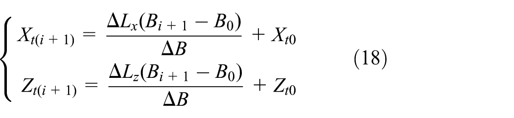
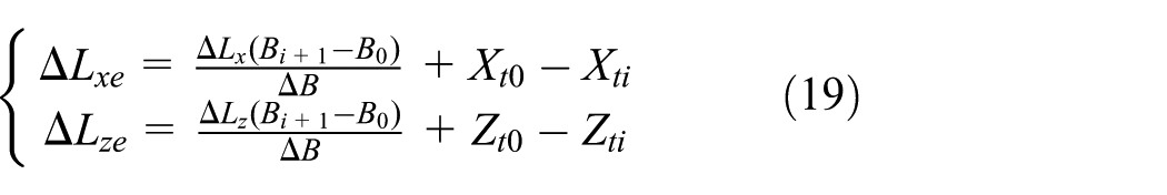
According to above three constraints of the maximum interpolation step length of every axis and the initial interpolation results such as

For five-axis linkage motion control of CNC machine tool, actual micro step interpolation still is the linear interpolation of every axis; under the constraints, the micro interpolation increment

Therefore, it is necessary to select a minimum of

Feed rate real-time planning and control method with RTCP function
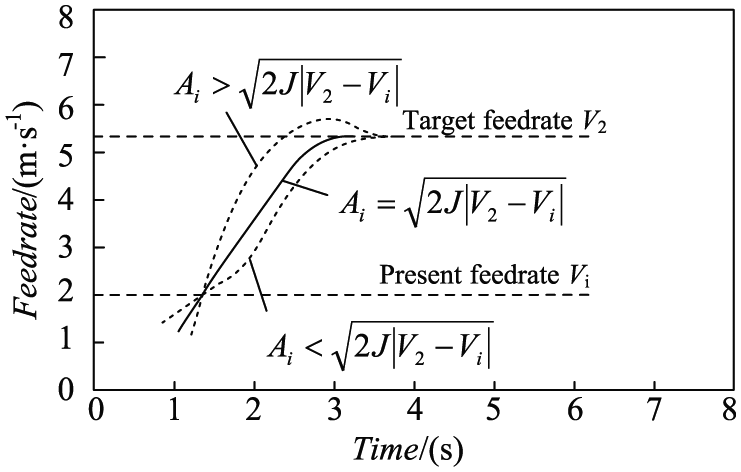
Supposing the target feed rate is
Different feed rate curves based on deferent present accelerations.
Change value of acceleration in each interpolation cycle is
1. Calculate the theoretical acceleration
To a typical S-shape feed rate curve, acceleration increases from zero; acceleration

Without loss of generality, let

Combining equations (26) and (27), the

Thus, the theoretical acceleration is

2. Calculate the actual acceleration

while
3. Calculate the feed rate within next interpolation cycle

4. Let
5. While

According to
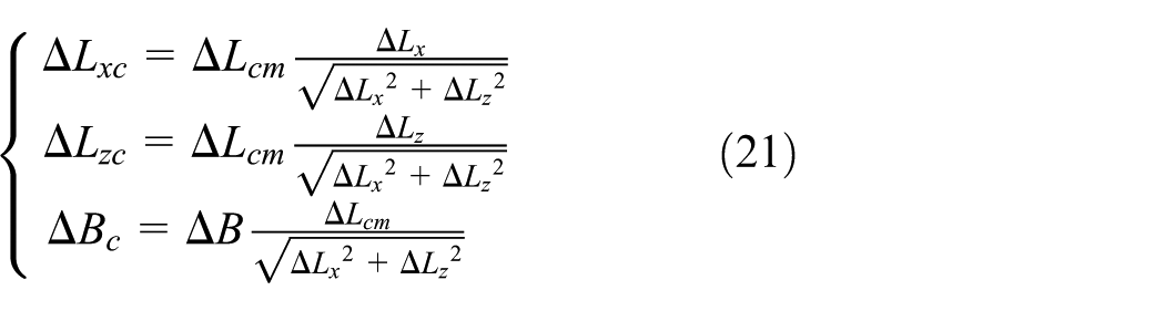
The interpolation points above-calculated are all on the original designed curve; thus, there are no radial errors but chord errors of short interpolation lines. The synthetic contour error

segment PiPi+1 shows that the synthetic contour error be compensated by the RTCP interpolation error.

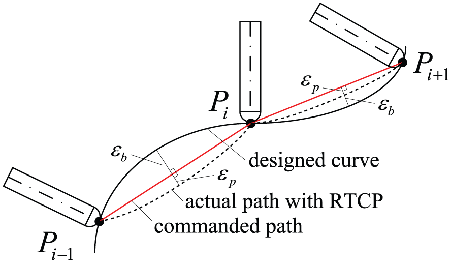
Comprehensive interpolation contour error with RTCP.
In the process of interpolation, contour error control must be carried out. When the contour error exceeds the allowable value, the interpolation step

Adaptive planning flow of interpolation feed rate.
Example analysis
To illustrate the comprehensive speed calculation method of five-axis interpolation with RTCP function, the interpolation path in the XZ plane with B axis is taken as an example. As analyzed above, if linear interpolation is carried out directly according to the original path, the over cutting error caused by rotation axis will reach 34.909 mm which will be caused scrapped workpiece directly. For multi-axis linkage path, it is less programmed into NC code directly to carry out multi-axis linear interpolation, but post processed in the process of code is designed. Subdividing the original path into multi micro path, and simulating the calculation using the self-designed software, Figure 13 shows the cutter location changing while different interpolation segments is inserted between two cutter locations.
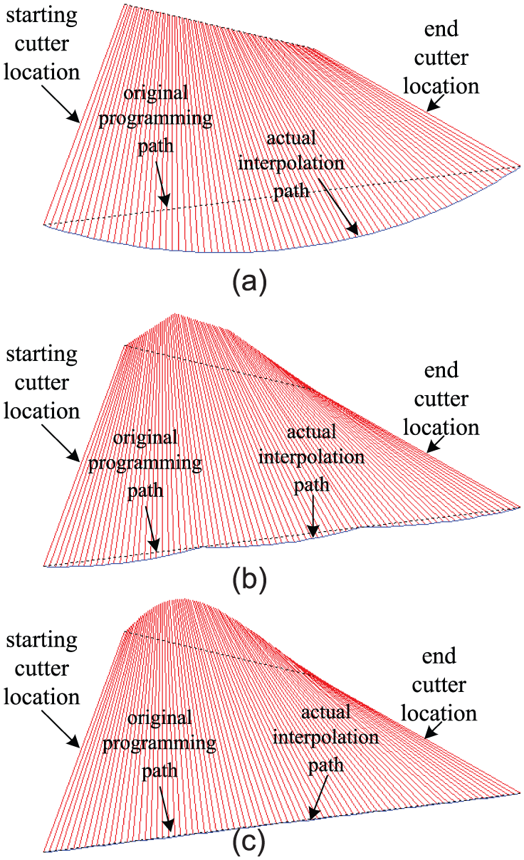
Cutter location trends with different interpolation segments: (a) cutter location trends with 1 interpolation segment, (b) cutter location trends with 3 interpolation segments, and (c) cutter location trends with 10 interpolation segments.
As shown in Figure 13(a), when there is only one interpolation segment, that is, without inserting any intermediate point, the actual RTCP interpolation degenerated into multi-axis linear interpolation, tool center path seriously deviates from the original programming path. With the increasing of interpolation segments, the actual tool center path tends to the original programming path more. In Figure 13(b), the Interpolation segments increase to three, nonlinear error caused by rotational motion reduces dramatically. In Figure 13(c), the Interpolation segments increase to ten, and the tool center path is close to the original programming path. But this post-processing method of inserting interpolation segments directly into cutter location will bring the following two problems to the subsequent machining.
In a standard approach, path refinement is generally divided by the original curve into many micro-segment, only the profile error of the workpiece in this refinement is considered, without considering the dynamic characteristics of machine tool and machining characteristics. In three-axis interpolation machine, as the profile error is controlled, the interpolation error will be limited in the controllable range. But in multi-axis CNC machine tools especially with the rotation axis or swinging axis, because the nonlinear error caused by rotating or swing motion superposes on the profile error, it results in the final interpolation error increasing, and the geometric precision of the workpiece is further decreased. At the same time due to the limit of the processing parameters such as the cutting speed and the actual bearing capacity of every axis in machine tool, the micro-segments which are post-processing refined in actual interpolation must be refined, which will result in great inconvenience to the feed rate real-time planning and the feed rate look-ahead.
After replacement of the machine tools or replacement of the cutting tool or tool wearing in machining process, because of the change of the swing tool bar length, the NC code generated from original post-processing will no longer applicable, and must be post processed again to regenerate according to the new machine tool structure parameters, thus the auxiliary operation time will be increased and the overall processing efficiency will be greatly reduced.
For perfecting the standard approach, an algorithm of interpolation feed rate planning under comprehensive constraints is proposed. The main idea of the algorithm is, real-time considering interpolation nonlinear error, machining parameters and carrying capacity of each axis, calculate the maximum interpolation step length of each axis in every interpolation cycle, so as to control the comprehensive feed rate of multi-axis synchronous CNC machining. The ultimate goal is to obtain optimal result in terms of machining precision, efficiency, and stability.
Supposing in NC machining with a swing axis, the swing processing nonlinear error limit is 0.0002 mm and the largest cutting feed rate is 7000 mm/min, the maximum allowed velocity of X and Z axes in swing center is 8000 and 5000 mm/min, respectively, the maximum allowed swing angular velocity of B axis is 6000°/s, and the interpolation cycle is 1.5 ms.
As shown in Figure 14, the interpolation step length and interpolation nonlinear error of a standard approach are calculated by CAM system. Interpolation segments are 426 and it may cause the interpolation step length to be too small and would reduce the feed rate while the interpolation cycle is fixed.
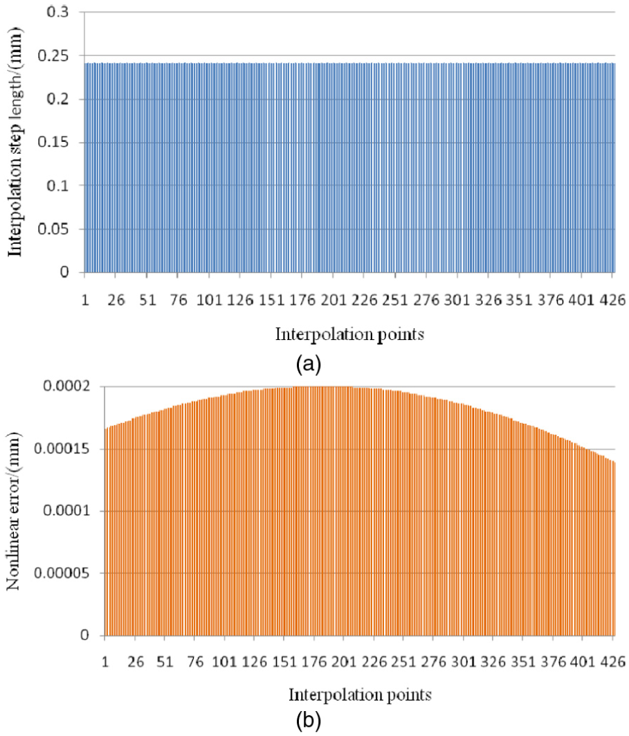
Interpolation step length and nonlinear error of standard approach: (a) interpolation step length of each interpolation segment and (b) nonlinear error in each interpolation segment.
As shown in Figure 15, the proposed algorithm with RTCP executes on the basis of CLF. All the interpolation nonlinear errors are controlled and the synthetic contour errors are below the permit value, but the interpolation step length could increase near start point and end point; thus, the interpolation segments reduce to 407. While considering machining parameters and carrying capacity of every machine axis comprehensively in one interpolation cycle, the small interpolation step length in every interpolation cycle will lead to very small interpolation nonlinear error, so the interpolation path accuracy is greatly improved.
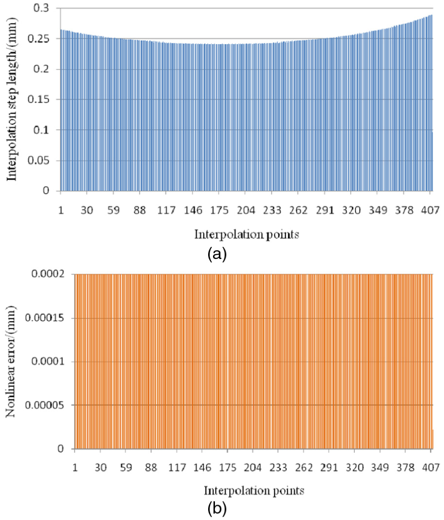
Interpolation step length and limited maximum nonlinear error with proposed RTCP function: (a) interpolation step length of each interpolation segment and (b) nonlinear error in each interpolation segment.
The interpolation step length in proposed algorithm varies according to the tool vector, thus will bring the tool center point feed rate fluctuations, and reduce the surface quality of the workpiece machined. In the practical application, the acceleration control of motion axis and the smoothing control of feed rate need to be considered (Figure 16). Feed rate control is generally realized by corresponding deceleration mode in actual interpolation. If there are subsequent interpolation lines, connecting velocity planning and velocity look-ahead at the junction should be carried out according to deceleration capacity of each axis. After setting the starting speed, jerk, translational axes acceleration, swing axes acceleration, stop speed and other parameters in the CNC system, calculation of interpolation coordinates and feed rate for practical application are shown in Figure 16. The increase of the interpolation segments make the speed switch between multi path smoothly, and the deceleration control for reducing switching speed is carried out in path junction, and the nonlinear error is further reduced.

Interpolation step length and nonlinear error of practical application by acceleration control: (a) interpolation step length of each interpolation segment and (b) nonlinear error in each interpolation segment.

Measured computation time of the algorithm: (a) interpolation step length of each interpolation segment and (b) nonlinear error in each interpolation segment.
The proposed algorithm must be completed within one interpolation cycle; otherwise, it will cause the machining code data “hungry.” It contains calculations about four constraint conditions. Where the constraint condition of tool center point cutting speed and another one of tool swing center rotating speed only involve in the coordinate transformation and thus lead to less computation time. For calculation of interpolation nonlinear error with RTCP, equation (16) is rather complex, but according to equation (17) and Figure 7, maximum nonlinear error is at the point
Verified by actual machining
The algorithm is verified by applying to a self-developed four-axis CNC system based on PC and motion control card. The CNC system can be configured to a multi-axis linear interpolation or interpolation with RTCP function, and the processing parameters is set as the same as in the aforementioned algorithm analysis. The data such as the interpolation coordinate and feed rate in every interpolation cycle are real-time stored in advance by the driver and then be read by the host computer software. As shown in Figure 18, the selected workpiece is a typical blade of variable cross section and is engraved and milled by a R2 ball end milling cutter. Any cross sections of the workpiece are composed of multiple segments of free curve, which is shown in Figure 19. In order to ensure the quality of processing, the specific curve interpolation is completed by linkage of the swing axis B, linear X and Z axes.
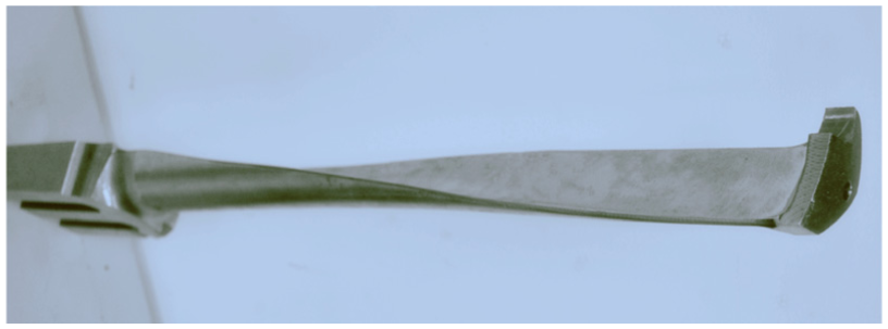
A typically variable-section blade workpiece.

One of section paths of the blade.
Three kinds of methods are used for multi-axis interpolation: first is to carry out multi-axis linear interpolation by CLF file, second is to use the corresponding post-processing program to complete the linear interpolation based on precise tool length by converting the original CLF code with tool vector into standard G-code of rotating tool center motion directly, and the third is to configure the CNC system into RTCP function interpolation using cutter location coordinates and tool vector data in the CLF.
Figure 20 shows the machining results by the original CLF. It can be seen that the system does not carry out refinement post-processing of nonlinear error control and enable RTCP function in interpolation machining, but directly carry out the axis linear interpolation, and larger interpolation nonlinear error is generated in each segment interpolation. So the actual interpolation path deviates from short line segment path of original design of profile approximation, and blade margin appears obvious phenomenon of over cutting, and processed component completely does not meet the requirements. Figure 21 shows the workpiece machined by multi-axis linear interpolation from the post-processing code which takes the interpolation nonlinear error allowed value as the maximum error control value in post-processing, so the interpolation nonlinear error meet the expected requirement and the feed rate is fast. But because of not fully considering the machine overload capacity for the moving ability and the acceleration of the rotational tool center, at the small curvature radius of the blade section curve, swing axis angle will vary greatly by a certain interpolation step length, thus easily leads to machine tool motion overload, the shake of machine tool is greatly enhanced, and the workpiece surface quality is more rough. Figure 22 shows the workpiece machined by the RTCP interpolation algorithm with swing axis, and the nonlinear error limit is 0.005 mm, the maximum cutting feed rate limit is 1000 mm/min, the allowed maximum speed limit at swing center of X and Z axes is 3000 mm/min and 2000 mm/min, respectively. Considering the preset interpolation nonlinear error, cutting parameters, and bearing capacity of the machine tool, feed rate will real-time change according to interpolation cycle. The actual interpolation calculation shows that the weightings of limited factors on interpolation step length are different of the curve in different areas. At points B and D of section curve, due to the large curvature radius and the little changes of swing axis angle, interpolation nonlinear error is not the main factors of feed rate, so feed rate is high. At points A and C of section curve, due to the small curvature radius and the great changes of swing axis angle, the interpolation nonlinear error and motion speed of the swing center must be limited, and the feed rate decreases; thus, the machining accuracy and surface quality improve. Although the curvature radius at points B and D is similar, because RTCP interpolation nonlinear error at point D has some compensative effect on profile error of processing code, the interpolation step length at point D is slightly longer than the step at B point and furthest improves machining efficiency, and overall efficiency is lower than the one of machining by post-processing code. Figure 23(a) shows the real-time feed rate by proposed approach, the feed rate is still smoothly with RTCP interpolation nonlinear error control. Chart (b) shows the errors detected by the laser measuring system between the actual machining path and the original design path. It shows that as the feed rate and curvature radius vary, the errors are adjusted adaptively. The errors result also contains the profile error of the generated code, so the final values are slightly over the limit of nonlinear error.
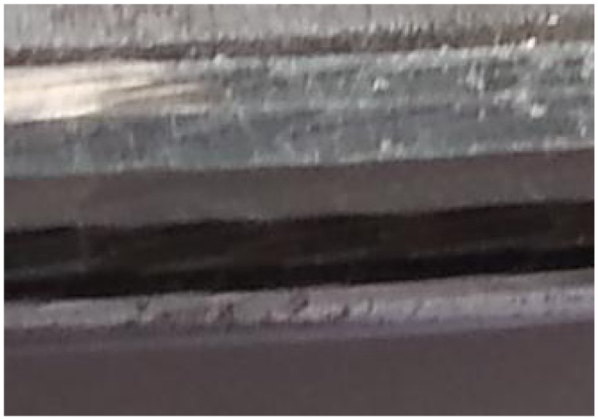
Manufacturing results by CLF.

Manufacturing results by post processed code.

Manufacturing results by RTCP interpolation.

Machining results by proposed approach: (a) feed rate by proposed approach and (b) error detection results by proposed approach.
Conclusion
A planning control method for the integrated five-axis feed rate with RTCP function is proposed in this article, the conclusions are as follows:
Five-axis NC machining tool path planning is interpolation according to the geometry information of components, but the rotating or swing motion in actual machining will cause a interpolation nonlinear error, and the error superposes on the path profile error, thus leads to a reduction in the machining precision.
The nonlinear error of five-axis interpolation is related to the angle increment of rotation or swing axis and tool length, under a certain tool length, the interpolation nonlinear error must be controlled by limiting each micro step increment or the interpolation step length of rotating or swing motion. The reduction of nonlinear interpolation error can be achieved by increasing the number of the interpolation steps, but how many interpolation steps should be take, as was not easy to determined. A maximum interpolation step length could be calculated within the permit of interpolation precision, and then fully considering the speed and acceleration of the drive axes of machine and other mechanical properties and machining characteristics of the tool center, a real-time feed rate planning and control approach for the integrated five-axis feed rate on the basis of analysis of interpolation nonlinear error with RTCP function is proposed. Thus, a stable machining is achieved and the workpiece surface quality is improved by controlling the nonlinear interpolation error. The approach could also be applied to the direct curve interpolation.
Footnotes
Academic Editor: Ramoshweu Lebelo
Declaration of conflicting interests
The author(s) declared no potential conflicts of interest with respect to the research, authorship, and/or publication of this article.
Funding
The author(s) disclosed receipt of the following financial support for the research, authorship, and/or publication of this article: The research in this article is supported by the Fundamental Research Funds for the Central Universities (No. NS2014045).