
Abstract
A new torque-loading method based on the direct torque control strategy for double motorized spindles is developed to achieve simulating the actual static and dynamic torque conditions and reduce the error of centration for back-to-back drive reliability bench test of double motorized spindles. First, the direct torque control theory and dynamometer control strategy of two motorized spindles are discussed, and then the control model of the motorized spindle is developed in the d-q coordinate system based on the direct torque control theory. In order to verify the proposed control model, the direct torque control strategy simulation model of double motorized spindles is constructed, and the virtual simulation tests are conducted. Finally, the torque-loading experiments controlled by the direct torque control theory with 10 and 7.3 kW motorized spindles are performed. Experimental results show that the profile of the desired torque can be accurately followed and the proposed dynamometer system has a good response ability of speed and torque.
Keywords
Introduction
Machine tools are the most basic equipment in the manufacturing industry. Technological level of machine tools is a sign of the development level of the equipment manufacturing industry. 1 Nowadays, high-grade machine tools in China have made great progress in speed, multi-axis linkage control, and complexity machining. However, an apparent gap of reliability has been a technical bottleneck for the development of computer numerical control (CNC) machine tools.2,3
Machine tools generally consist of several functional units. Therefore, improving the reliability of functional units is the key to improve the reliability of machine tools. As the main unit to generate cutting motion, a motorized spindle is a core unit of machine tools. For consisting of optronics, machine, electricity, liquid, and gas subsystems, themotorized spindle is the highest failure rate and lowest maintainability subsystem. 4 Reliability tests of motorized spindles are conducted to identify potential causes of failures. Based on these reliability tests, reliability evaluation could be performed and then improve the design of the tested motorized spindle.
For a long time, reliability tests of motorized spindles mainly rely on the field tracing tests because of the lack of loading simulation technology used for the accelerated reliability tests. Hence, loads of motorized spindles depend on the machining methods adopted by machine tools’ users. However, the working conditions in the field tests are uncontrollable and the test period is long enough, which cannot meet the increasing demand for product update. The conventional test approaches to evaluate the reliability and performance of the motorized spindle are running tests without loading, virtual simulation tests or torque-loading tests by a dynamometer. Among these methods, no loading tests, which is different from the actual loading conditions, are mainly conducted to measure the key performance. Therefore, these tests cannot replicate the actual motorized spindles working conditions. Furthermore, limited by the accuracy of the working conditions, virtual simulation results are also not reasonable.5,6 To evaluate the motorized spindle’s reliability and investigate potential problems, scholars and engineers performed lots of research on the motorized spindle’s reliability bench tests. Cao et al. 7 conducted a test for the motorized spindle of the grinding machines, and he obtained the grinder spindle vibration performance. Nevertheless, the ranges of the grinding force and torque were smaller for the limitations of the test samples. Li et al. 8 and Qiu and Liu 9 developed a motorized spindle performance test system using the non-contact electromagnetic loading method. Influencing by the magnetorheological fluid and electromagnetic, the testing system would generate a lot of heat in short testing time, which overheated the loading system. Therefore, it was impossible to conduct the reliability test for a long time period. JS Chen and KW Chen 10 and SC Chen et al. 11 developed two kinds of loading test systems for the motorized spindle using the mechanical spring and hydraulic cylinder. However, the accuracy of the dynamic and static performance was affected evidently by the friction that occurred between the tested spindle and the loading device.
As an alternating current (AC) induction motor, the motorized spindle is usually controlled by three control strategies such as the frequency conversion control method, the vector control method, and the direct torque control (DTC) method. In order to improve the reliability test efficiency and address the above problems, a new loading scheme based on the DTC method for double motorized spindles is proposed in this article. This article is organized as follows: section “Loading control theory of two spindles” outlines the DTC loading theory and the simulation of the proposed loading method is presented in section “Simulation of the dynamometer system.” The actual loading tests are conducted in section “Dynamic load test of the dynamometer system”; finally, section “Conclusion” concludes this article.
Loading control theory of two spindles
Description of DTC
DTC is a new type of frequency control technique which controls the stator flux and electromagnet torque directly in the stator coordinate without complicated coordinate transformation. It can enhance the static and dynamic performance for a variable frequency speed control system.
A block diagram of DTC strategy includes two hysteresis controllers which are shown in Figure 1. The stator flux controller imposes the time duration of the active voltage vectors, which can move the stator flux along the reference trajectory, and the torque controller determinates the time duration of the zero voltage vectors, which can keep the motor torque in the defined-by-hysteresis tolerance band. At every sampling time, the voltage vector selection block chooses the inverter switching state (SA, SB, SC), which reduces the instantaneous flux and torque errors.
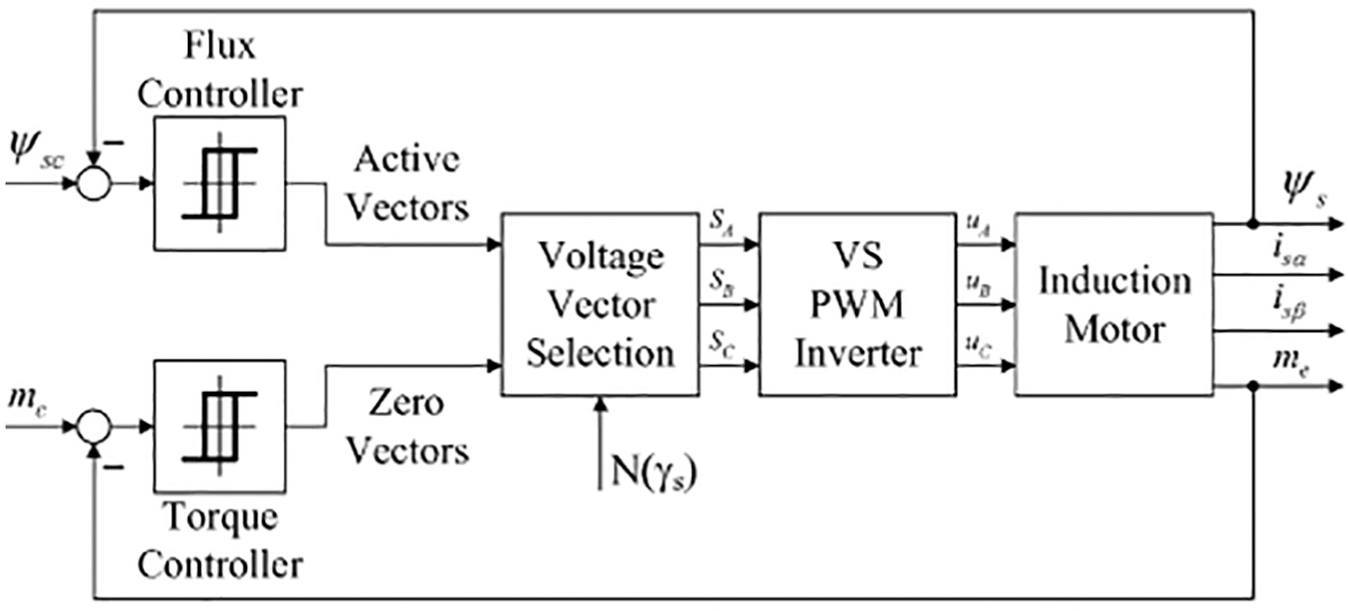
Block diagram of DTC strategy.
Basically, DTC strategies operating at constant switching frequency can be implemented by means of closed-loop schemes with proportion integration (PI), predictive/dead-beat, or neuro-fuzzy (NF) controllers. The controllers calculate the required stator voltage vector, averaged over a sampling period. The voltage vector is finally synthesized by a pulse width modulation (PWM) technique, which in most cases is the space vector modulation (SVM). During motor operation, the DTC scheme selects many times the zero voltage vectors to choose the optimal vector, which can be used to control working conditions of the stator flux. Meanwhile, the computed stator flux and torque are compared with the reference to ensure the spindle in an expected state.
When a motor is controlled by DTC schemes,12,13 the electromagnet torque is given by

where vectors of
Equation (1) shows that the electromagnet torque can be controlled by changes of the amplitudes of the stator and rotor magnetic motive force and changes of their corresponding angles. If the amplitude of flux linkage remains constant, equation (1) can be transformed into equation (2)

where
For
where
The electrical time constant is normally much smaller than the mechanical time constant, so the reaction speed of the stator flux is usually higher than that of the rotor. Therefore, when the flux linkage and the amplitude of stator flux are kept constant, the electromagnet torque can be controlled by changing the angle between the stator flux and current.
Dynamic dynamometer control strategy of two motorized spindles
The motorized spindle is similar to a synchronous or induction motor. Thus, the composite unit of a frequency converter and a motorized spindle can be equivalent to a dynamometer. That means the composite unit can realize a four-quadrant vector-controlled rotation. If the frequency of a motorized spindle controlled by the converter is higher than the actual one, the motorized spindle would operate in the electric state. On the contrary, when the frequency of a motorized spindle controlled by the converter is lower than the actual one, it would operate under the generator state. If one composite unit is coupled to the other composite unit by a coupler, and two composite units are controlled by different control strategies, this would make one motorized spindle run in the generator state and the other one operates in the electric state. Then two motorized spindles would be tested simultaneously. Therefore, the dynamometer system of two motorized spindles consists of two sets of composite units, which are powered by two sets of three-phase service, respectively.14,15
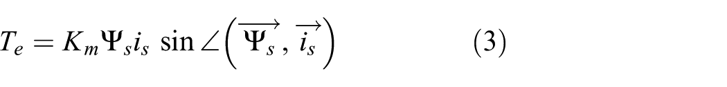
When one motorized spindle operates in the electric states (called the tested motorized spindle) and the other one runs in the generator states (called the loaded motorized spindle), parts of the electromagnetic torque of the tested motorized spindle are used to overcome the friction torque, and the other parts to drive the loaded spindle. It means that the tested motorized spindle overcomes the electromagnet torque of the loaded spindle and drives it rotating coaxially. The electromagnet torque of the tested motorized spindle is
where
The electromagnet torque of the loaded spindle can be expressed as

where
Substituting equation (5) into equation (4) gives

However, when the tested motorized spindle operates in the generator states and the loaded spindle in the electric states, it means that the loaded one drives the tested one and the electromagnet torque is described as

Motorized spindle equation
Compared with the static coordinate system, there is one new input variable of

where
The flux linkage equation is

where Ls, Lr, and Lm are the stator, rotor, and magnetizing inductances, respectively.
The rotor of the motorized spindle is a cage form rotor, so urd = urq = 0. Substituting equation (9) into equation (8) can give

where p is the differential operator.
The electromagnet torque in the d-q coordinate system can be shown as

where np is the number of poles of a motorized spindle.
Equation (9) is then substituted into equation (11) to yield

Simulation of the dynamometer system
Simulation model
The dynamometer system of two motorized spindles consists of two motorized spindles, a rectifier regulator, a speed controller, a DTC controller, and an inverter. The capacity and speed of the loaded motorized spindle are higher or equal to the tested one. The simulating schematic of the dynamometer system using the simulation package Simulink is shown in Figure 2.
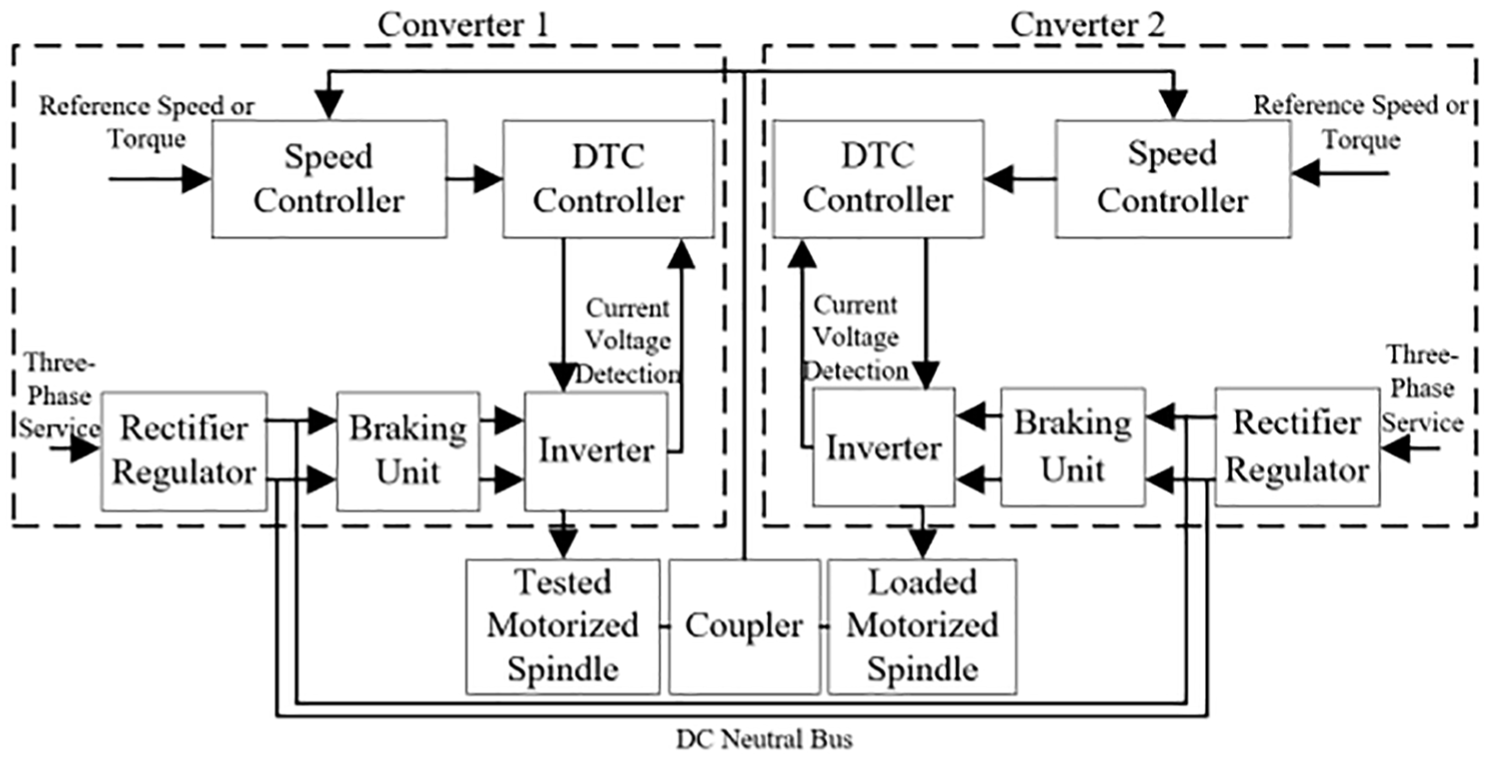
Schematic of the dynamometer system.
Figure 2 illustrates that the tested motorized spindle is coupled coaxially to the loaded one. Converter 1 controls the output speed of the tested motorized spindle by the speed control mode, while the loaded one rotates with the torque changing in the torque control mode by Converter 2. The system realizes the expected speed or torque by the speed or torque controller. Simultaneously, the speed and DTC controllers read the stator voltage and current at the beginning of a particular switching period to determine the best switching states for the inverter. Then one converter would utilize the reference voltage to achieve the reference speed or torque of the loaded motorized spindle. Moreover, the direct current (DC) neutral bus of two converters is connected to realize energy feedback and utilization.
Simulation results
Test of constant torque with changing rotation speed
Test of constant torque with a stair step rotation speed
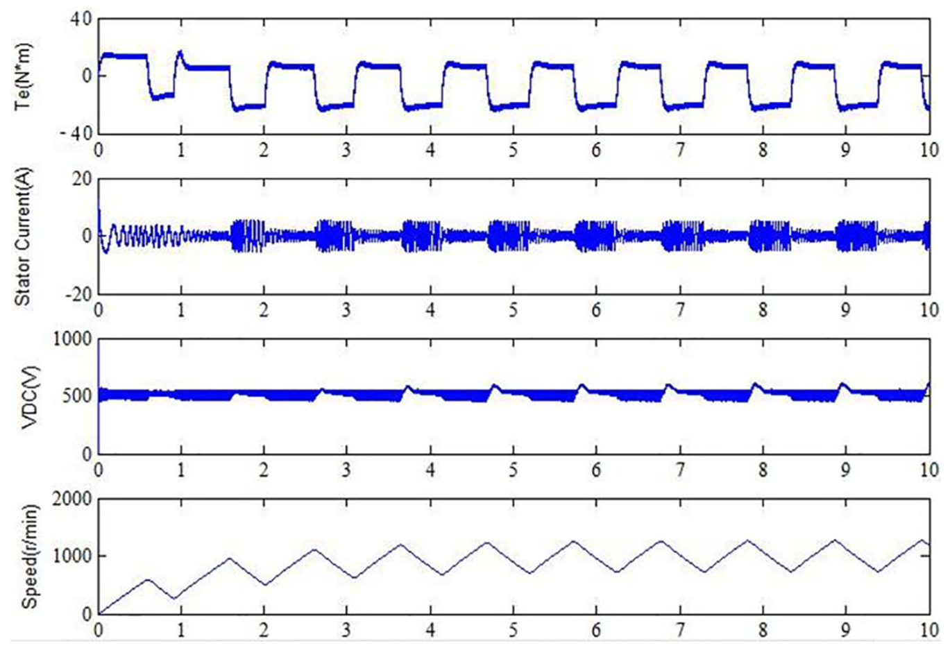
When t ∈ (0–1)s, (1–4)s, the reference torque of the loaded motorized spindle is set at 0, 400 N m, respectively. The reference speed is set at 400, 800, 1200 r/min when t ∈ (0–1)s, (1–2)s, (2–3)s, respectively. The response waveforms of the two motorized spindles simulated in Simulink are shown in Figures 3 and 4. It shows that when t is within the range of 0 s–0.4 s, the torque of the loaded motorized spindle is zero. In order to improve the speed, the electromagnet torque of the tested one is a high value, corresponding that the amplitude of the stator current is very high. At this moment, the tested one is in the electric state, while the loaded one in the generator state. And the electric power generated by the loaded one improves the voltage of the DC neutral bus and provides power for the tested one through the DC neutral bus. Therefore, within the range of 0 s–0.4 s, the voltage and current of the DC neutral bus are both higher than the normal running status (Figure 5 and 6).

Response waveforms of the tested motorized spindle with a stair step rotation speed driven by a constant torque in the Simulink environment.

Response waveforms of the loaded motorized spindle who generated a constant torque with a stair step rotation speed in the Simulink environment.

Current of the DC neutral bus when the dynamometer system is in the constant torque mode with a stair step rotation speed.
Stator flux linkage when the dynamometer system is in the constant torque mode with a stair step rotation speed.
When t ∈ 0.4 s to 1 s, the speed of the dynamometer system reaches the reference point, 400 r/min. To keep the system stability, the electromagnet torque of the tested motorized spindle and the output torque of the loaded one turn to zero. Therefore, the stator current of the tested one is kept low, similar to the voltage and current of the DC neutral bus.
When t = 1 s, the torque turns to 400 N m quickly and the reference speed of the dynamometer system becomes 800 r/min. To improve the speed, the torque of the tested one turns to about 200 N m, so the amplitude of the stator current increases quickly. At this moment, the tested one is in the generator state, while the loaded one in the electric state. The voltage and current of the DC neutral bus are also higher than the previous.
To guarantee the stability of the dynamometer system within the range of 1.4 s–2 s, the electromagnet torque of the tested one and the output torque of the loaded one turn to equal and opposite values. The former works in the generator state, while the latter in the electric state. At this moment, the current of the DC neutral bus increases because of the increase of the torque of the tested motorized spindle. The states of the dynamometer system from 2 s–4 s are similar to the states within the range of 1 s–2 s.
As illustrated in Figure 7, waveforms of the stator flux linkage show that the circle of the stator flux is regular with a small fluctuation. Thus, the simulation results prove that the proposed control strategy is fairly accurate with the actual conditions. The speed of the tested motorized spindle and torque of the loaded one can change with a smaller overshoot, short response, and stability according to the expected value and control states. In general, the dynamometer system of two motorized spindles exhibited good control and response ability of speed and torque in the constant torque test.
Response waveforms of the tested motorized spindle with a sinusoidal rotation speed driven by a constant torque in the Simulink environment.
Test of constant torque with a sinusoidal rotation speed
When t ∈ (0–1)s, (1–10)s, the reference torque of the loaded motorized spindle is set at 0, 400 N m, respectively. The reference speed is set at a sinusoidal form, whose amplitude is 400 r/min. The response waveforms of the two motorized spindles simulated in Simulink are shown in Figures 7 and 8.

Response waveforms of the loaded motorized spindle who generated a constant torque with a sinusoidal rotation speed in the Simulink environment.
When t ∈ 0.4 s to 1 s, the electromagnet torque of the loaded motorized spindle is zero, in order to improve the speed of the dynamometer system to 600 r/min, the torque of the tested motorized spindle increased greatly and then keep a relatively stable value. When the speed equals to 0, the torque of the loaded spindle approximates to 0. However, when t is greater than 1 s, the torque of the loaded motorized spindle is set at 400 N m. As shown in Figure 9, the changing law of the tested spindle torque changes with that of the loaded spindle speed. Meanwhile, to save the energy, the current of the DC neutral bus changes with the changing law of the loaded spindle speed. But at the initial time, the DC neutral bus current is greater than the other instant, which means part of energy are provided to the tested spindle and part are feedback to the power grid (Figure 10).

Current of the DC neutral bus when the dynamometer system is simulated in the constant torque mode with a sinusoidal rotation speed.

Stator flux linkage when the dynamometer system is simulated in the constant torque mode with a sinusoidal rotation speed.
Test of constant speed with changing torque
Test of constant speed with a stair step torque
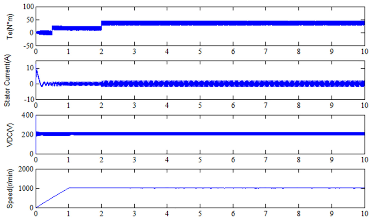
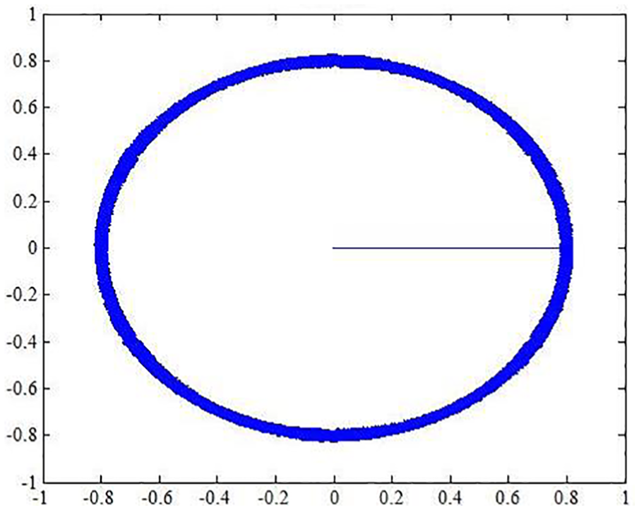
The speed of the tested motorized spindle is set at 1000 r/min, when the torque of the loaded one is 0, 200, 400 N m, respectively, corresponding that t is equal 0, 0.5, 2 s. The response waveforms of two motorized spindles are shown in Figures 11–14. The figures show that the stator flux circle is fairly regular with a smaller overshoot, while the speed of the tested one and torque of the loaded one have the ability to respond quickly with a smaller overshoot. This result indicates that the dynamometer system of two motorized spindles exhibited good control and response ability of speed and torque in the constant speed test.

Response waveforms of the tested motorized spindle with a constant rotation speed driven by a stair step torque in the Simulink environment.
Response waveforms of the loaded motorized spindle who generated a stair step torque with a constant rotation speed in the Simulink environment.
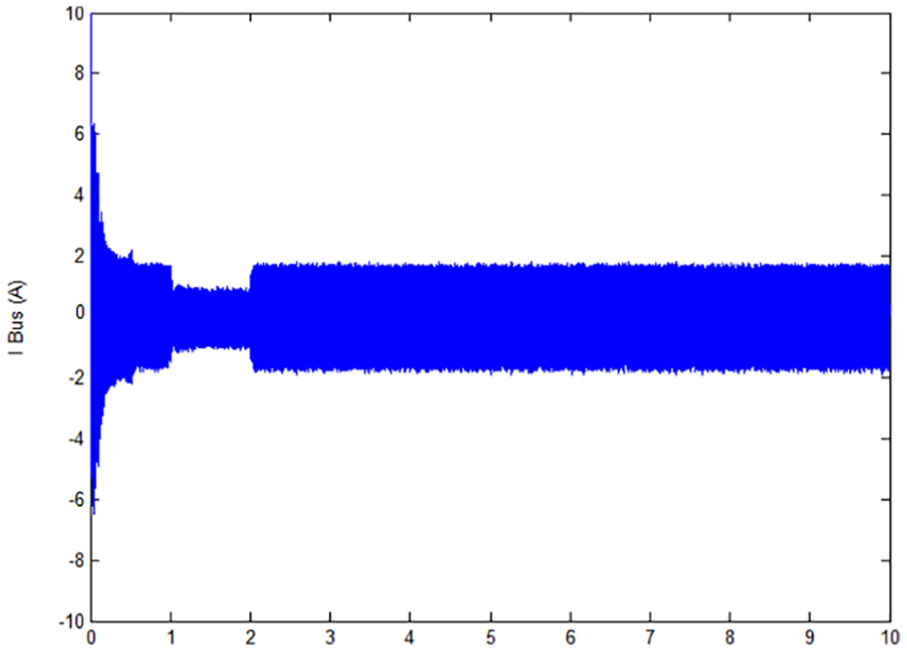
Current of the DC neutral bus when the dynamometer system is in the constant rotation speed mode with a stair step torque.
Stator flux linkage when the dynamometer system is in the constant rotation speed mode with a stair step torque.
Test of constant speed with a sinusoidal torque
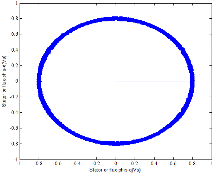
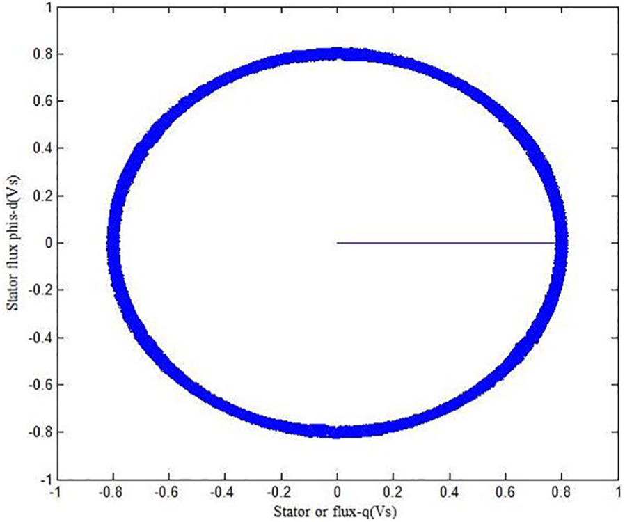
The speed of the tested motorized spindle is set at 1000 r/min and the torque of the loaded one is a sinusoidal torque whose amplitude is 40 N m. The response waveforms of two motorized spindles are shown in Figures 15 and 16. During 0 s to 0.2 s, in order to improve the rotate speed of the tested spindle, the tested spindle torque is higher than that of the loaded one and the curves of the loaded spindle torque and the current change obviously at the initial state. But when t is greater than 0.2 s, the system has a relatively steady property, while the torque of the tested spindle is higher than the other one until the speed reaches 1000 r/min. When t is greater than 1 s, the system keeps a stable state. Figures 17 and 18 show that the stator flux circle is fairly regular with a smaller overshoot. This indicates that the dynamometer system exhibited good control and response performance in the constant speed test with a sinusoidal torque.

Response waveforms of the tested motorized spindle with a constant rotation speed driven by a sinusoidal torque in the Simulink environment.

Response waveforms of the loaded motorized spindle who generated a sinusoidal torque with a constant rotation speed in the Simulink environment.

Current of the DC neutral bus when the dynamometer system is simulated in the constant rotation speed mode with a sinusoidal torque.
Stator flux linkage when the dynamometer system is simulated in the constant rotation speed with a sinusoidal torque.
Dynamic load test of the dynamometer system
Hardware design
Based on the dynamometer control strategy, a bench test of the dynamometer system has been constructed. The block diagram of the test bench is shown in Figure 19.
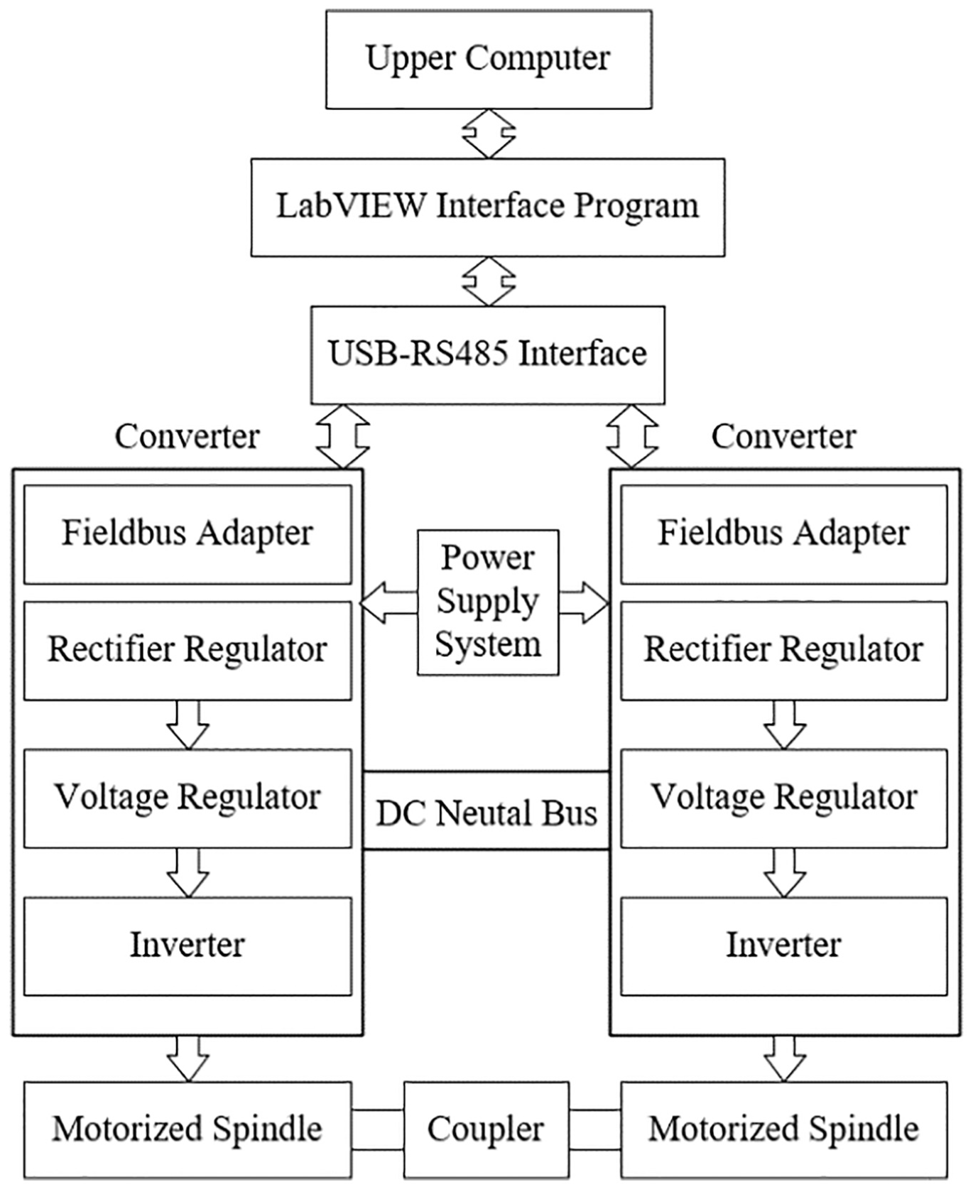
Block diagram of the dynamometer system.
The dynamometer system consists of two sets of composite units of which two motorized spindles are coupled by a torque transducer. The composite units are shown in Figure 20.

Connection diagram of the dynamometer system.
Software design
Parameter setting of the converter
Two motorized spindles are controlled by a 0.55–250 kW, 0.75–350 hp ACS880 thyristor, which can be used to control the permanent-magnet synchronous motor, asynchronous AC motor, and AC induction servomotor. For different control modes, control parameters can be set through the communication interface. So the tested motorized spindle can be controlled with the speed control mode by converter 1 and the loaded one controlled with the torque control mode by converter 2.
Table 1 shows that for the different control modes, drive parameters of the fieldbus adapters are also different. Moreover, parameters of start-stop mode (No. 20 and 21 parameters) and control mode (No. 22 parameters) should be modified according to the technical parameters of the motorized spindle (No. 99 parameters).
Parameters setting of two converters.

FBA: Fieldbus adapter; ABB: Asea Brown Boveri Ltd.
Control program of the dynamometer system
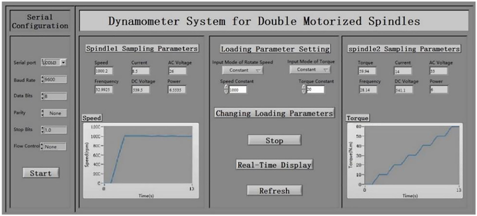
The control program of the dynamometer system consists of process control, data acquisition, data processing, real-time display, data initialize, and data storage. Therefore, the communication interface can display the real-time parameters of the dynamometer system, such as speed of the motorized spindle, torque, frequency, and neutral bus voltage. Figure 21 represents the front panel of the program, whose block diagram program is designed by VISA functions. The speed and torque control schematics are programmed by LabVIEW and they are shown in Figure 22(a) and Figure (2). Speed control commands of the motorized spindle in Figure 22(a) are generated by VI subfunction, which are written into converter 1 through VISA.Figure 22(b) shows that start command is inputted to converter 2, and then the speed control subfunction generates the torque control command to control the electromagnet torque of the loaded motorized spindle. To prevent the motorized spindle from reversing during experiments, the terminal command must be inputted to converter 2 before converter 1 and the schematic is shown in Figure 22(c).

Front panel of the control program in LabVIEW.

Schematic of the control program: (a) schematic for speed change, (b) schematic for torque change, and (c) schematic for the dynamometer system braking.
Loading test of the dynamometer system
To verify the feasibility of the dynamometer system, loading tests are conducted using the developed dynamometer system. The tested motorized spindle is 293 V, 19 A, 7.3 kW, 2-pole, 300 Hz, and 18,000 r/min of the maximum speed spindle, while the loaded one is 300 V, 21.3 A, 10 kW, 2-pole, 400 Hz, and 12,000 r/min.
Constant torque tests
In order to verify the dynamic response property, the constant torque tests with a stair step rotation speed and a sinusoidal speed are conducted. The responding speed parameters are set through the front panel.
The torque of the tested motorized spindle is set at 30% of the nominal torque, and the speed is a stair step signal whose initial value is 200 r/min. As shown in Figures 23 and 24, the speed, frequency, DC neutral bus voltage, voltage, torque, current, and power of two spindles can be shown on the front panel of the upper computer in real time. Compared with Figure 4, the torque of the loaded motorized spindle increases to the reference value in about 1 s time, but the simulation test shows that it reaches the reference value momently. In addition, seen from Figure 3, the speed of the tested motorized spindle gets to the reference speed nearly linearly. While the real test shows that the increase laws of speed are nonlinear. When the speed is a sinusoidal signal, the simulation result shows that the speed of the tested motorized spindle follows to a perfect sinusoidal signal. But at the phase, the speed of the tested motorized spindle changes greatly, and then after about 2 s, it approximates to a stable state.

Dynamic responses of the tested motorized spindle with a stair step rotation speed driven by a constant torque in the test.

Dynamic responses of the tested motorized spindle with a sinusoidal rotation speed driven by a constant torque in the test.
When the dynamometer system operates in the constant torque mode, the speed and torque can change with the given values and have little fluctuations. The loading torque has about ±1% error and the rotate speed has about ±1 r/min error. Regardless of the speed of the tested motorized spindle changes quickly (a stair step signal and a sinusoidal signal), the torque of the loaded one can operate at the setting conditions. Hence, the dynamometer system exhibits good control and response ability under the constant torque conditions.
Constant speed test
When the speed of the tested motorized spindle remains constant, the real tests that the torque of the loaded motorized spindle is a stair step and a sinusoidal signal were conducted respectively. The dynamic responses of two spindles are shown in Figures 25 and 26.
Dynamic responses of the tested motorized spindle with a constant rotation speed driven by a stair step torque in the test.

Dynamic responses of the tested motorized spindle with a constant rotation speed driven by a sinusoidal torque in the test.
Compared with Figure 11, the law of the speed is similar and the speed increases to the reference speed with almost linearly increases with time. While the increasing tendency of the torque is different, the torque of the loaded motorized spindle in the real test increases to the next step in about 1 s time, but the simulation test shows that it reaches the reference value momently. When the torque is a sinusoidal signal, we can see that the torque of the loaded motorized spindle reaches the stable state faster that of the real test, but the overall trend is similar.
As shown in Figures 25 and 26, the dynamometer system operates smoothly with fast speed and torque responses. The speed response has a small overshoot without torque overshoot. Therefore, the dynamometer system exhibited good control and response under the constant speed conditions.
Conclusion
In order to improve the loading precision and reliability test efficiency for motorized spindles, a new torque-loading method based on the DTC strategy for double motorized spindles is developed. The motorized spindle reliability bench tests and simulation tests are conducted in this article. Conclusions are as follows:
For addressing the problems that the torque and high speed are hard to load on the motorized spindle, a dynamometer system for double motorized spindles is constructed. The dynamometer system consists of two motorized spindles, which are connected by a coupling. The coupling ensures the alignment of the two motorized spindles. One motorized spindle is regarded as the loaded motorized spindle and the other serves as the tested one. The loaded and the tested one are controlled by two transducers which are composed of an inverter, rectifier, and other modules in torque control and speed control, respectively. The two motorized spindles in the reliability test can be experimented simultaneously, which improves the efficiency of the reliability test.
In the experiment, the torque of the loaded spindle is controlled by the DTC theory, which takes the torque directly as the controlled variables, rather than controlling spindle torque indirectly by controlling variables such as the spindle current and the flux linkage. In other words, the analysis method of space vector pulse width modulation is used in DTC to control the stator flux linkage and motorized electromagnetic torque straightly. This method can calculate the stator flux linkage and motorized electromagnetic torque in the coordinate system directly without complex coordinate transformation. Furthermore, PWM pulse width modulation and high dynamic property of the system are realized by flux linkage and direct control torque. Through rectifier, the bidirectional flow of electric energy between the power grid and the spindle is realized, and the energy of the reliability test of the motorized spindle has economized.
Two modes of constant speed control and constant torque control have been simulated and tested, respectively. The results indicate that the loaded motorized spindle working in the generator state can provide the load for the tested one, which cannot only maintain the constant torque, but also change the torque dynamically. In addition, the test one can be driven to rotate if the load one works in the electric state. When the tested one switches between different torque or speed, or the loading spindle changes from the electric state to the generator state, the whole process is smooth relatively and runs at tremendous speed. Besides, the DC buses realize the bidirectional flow of energy, which can save energy. Therefore, the proposed dynamometer system has a great value in engineering application.
Footnotes
Acknowledgements
The authors thank for JLU Science and Technology Innovative Research Team (JLUSTIRT).
Handling Editor: Zengtao Chen
Declaration of conflicting interests
The author(s) declared no potential conflicts of interest with respect to the research, authorship, and/or publication of this article.
Funding
The author(s) disclosed receipt of the following financial support for the research, authorship, and/or publication of this article: National Science and Technology Major Project (Grant No. 2018ZX04014001), Jilin Province Science and Technology Development Funds (Grant No. 20180201007GX and 20190302017GX), Special Plan of Provincial School Building (SXGJSF2017-2), Technology Development and Research of Jilin Province (Grant No. 2019C037-01), Changchun Science and Technology Planning Project (Grant No. 19SS011), Science and Technology Project of Jilin Provincial Education Department (Grant No. JJKH20180132KJ), Postgraduate Innovation Research Plan of Jilin University (Grant No. 101832018C188).