
Abstract
Manufacturing and, in particular, machining are responsible for a significant portion of global industrial energy consumption (25%). Previous research has shown that precise selection of cutting parameters can improve the energy consumption of machining processes. Cryogenic machining has attracted significant attention for improving the machinability of difficult-to-machine materials while also eliminating the environmental and health issues associated with the use of cutting fluids. Despite the advantages, there is a considerable research gap in cryogenic milling operations. This article investigates the effect of cryogenic cooling using liquid nitrogen in end milling of Ti-6Al-4V. A robust and rigorous methodology was developed and a series of machining experiments were conducted using a combination of cutting parameters repeated at dry, flood and cryogenic cooling environments. The investigations indicated that cryogenic cooling considerably reduce tool wear when compared to dry and flood cooling while allowing for using higher cutting speeds. The cutting tool used for cryogenic machining at 200 m/min cutting speed, 0.03 mm/tooth feed rate and 5 mm depth of cut showed minimum flank wear. Furthermore, the investigations demonstrated that using the machine’s coolant pump in flood cooling resulted in higher power and energy consumption than dry and cryogenic cooling. This article clearly shows that higher material removal rates are required in order to minimise specific machining energy. Therefore, since cutting speed is limited in dry machining, cryogenic machining is the most favourable as higher cutting speeds can be used. Using cryogenic machining at 200 m/min cutting speed resulted in an 88% reduction in energy consumption of the machine tool as compared to flood cooling at 30 m/min while minimum tool wear (10 µm) was detected. This clearly demonstrates the significant capabilities of cryogenic machining when compared with more conventional machining approaches.
Keywords
Introduction
Industrialisation and economic development at the cost of environment have been a matter of concern for centuries. 1 The increasing global power consumption and significant reliance on fossil fuels have raised serious concerns on meeting the demand, sustainability of the energy sources and their adverse impact on the environment. It has been reported that fossil fuels contribute to more than 80% of the global energy consumption 2 while the demand for energy is predicted to increase by 45% in 2030 as compared to 2011’s levels. 3 Jacobson and Delucchi 4 have proposed a large-scale conversion towards clean, renewable and reliable energy sources as a way to overcome energy insecurity and increasing environmental issues such as climate change and air and water pollution. However, the prospect of energy for the foreseeable future is still based on fossil fuels, and therefore, energy efficiency and rationalisation of energy consumption are the most effective methods of controlling increased environmental impacts of energy consumption. 3
The manufacturing sector is responsible for almost 30% of the global energy consumption5,6 with machining being one of the key components of manufacturing. It has been reported that 99% of the environmental impact of machining is due to electrical energy consumption. 7 Knowing that energy consumption is the integral of power consumption over time, many researchers8,9 have identified that machine tools’ idle power consumption is the single largest component of machine tools’ power consumption profile. Apostolos et al.10,11 reported that in laser machining, a significant portion of machines’ energy consumption is required for running the machine while only 5.7% of the total energy consumption is used for actual machining operation. The authors identified that in order to increase the efficiency in laser machining, higher laser powers and pulse are more favourable as less time is required to heat the workpiece material and less energy is lost between each pulse. 10 In grinding operations, Salonitis12,13 reported that almost 80% of the total effective power is drawn by the coolant pump and grinding wheel motor. Dahmus and Gutowski 14 reported that only 14.8% of the total machine tools’ energy consumption is used for material cutting. Based on this, Salonitis and Ball 5 proposed the following model for energy consumption in machining

where Eprocess is the energy required for cutting the material and Eperipherals is the energy consumed for running various components of the machine tool, for example, coolant pump and controls. Interestingly, the Eperipherals is not limited to material cutting processes, for example, machining, and it can be identified in other processes. For instance, Salonitis et al. 15 found that only 30% of the total energy consumed in casting is used for melting the material. Based on this, Mahrabi et al., 16 Salonitis et al. 15 and Dai and Jolly 17 proposed a number of techniques which can significantly reduce the energy consumption in foundry and casting operations.
In conventional machining operations, Balogun and Mativenga 18 identified that the cutting tool tip energy is considerably lower than the energy required for running the machine tool at no load. Therefore, they recommended minimising the idle time of the machine tool. Minimising the energy consumption of the machine tools when idle requires the use of more energy-efficient equipment improved design and a dematerialised machine frame/body. 18 However, energy conscious process planning can significantly reduce the energy consumption of a machine tool during material cutting.9,19 Similarly, Avram and Xirouchakis 20 have identified excess operating time and unreasonable load on the machine tools’ drives as two major ways of wasting energy which can be addressed in process planning for machining operations. Aramcharoen and Mativenga 9 have identified that the machine tools’ energy demand is generally affected by tool wear and tool path which are generally overlooked. Various researchers21,22 have identified the importance of considering tool wear/life and energy consumption, simultaneously. This is mainly due to the fact that cutting parameters not only affect the material removal rate but also have the significant effect on tool wear. 22
While 80% of Ti-6Al-4V is used in aerospace and medical industries, it is described as the most used titanium alloy forming 50% of the global titanium metal production. 23 Titanium and its variant alloys are one of the most commonly used structural materials in aerospace and medical industries due to high specific strength, hardness and wear resistance. 24 High cutting temperatures, short tool life and poor surface integrity are inherent characteristics that make machining titanium notoriously difficult. Due to the poor thermal conductivity, the heat generated at the cutting zone accumulates resulting in thermal softening of the cutting tool, adhesion and diffusion wear. It is reported that about 80% of the heat generated at the cutting zone is conducted through the cutting tool as compared to 50% for steels. 25 Titanium is chemically reactive to all known cutting tool materials and welds onto the cutting tool resulting in chipping and premature tool failure. 25
In order to control the heat generated at the cutting zone, the generous use of cutting fluids at high pressures is typically recommended. 26 However, cutting fluids and, more specifically, water-miscible fluids (soluble oil or emulsion) are considered as environmental pollutants which require constant maintenance and costly disposal. 24 Moreover, many governmental organisations such as the UK Health and Safety Executive (HSE), 27 US Occupational Safety and Health Administration 28 and Canadian Centre for Occupational Health and Safety 29 have identified cutting fluids as hazardous substances. Cutting fluids require routine maintenance to reassure their performance as bacterial and fungal growth can deteriorate their cooling/lubrication characteristics.24,30 The presence of harmful chemicals such as formaldehyde and aromatic chains and the existence of dead bacterial masses such as endotoxin are proven sources of health hazards. 31 The exposure to cutting fluids is linked to a group of occupational health diseases ranging from asthma and dermatitis32,33 to various types of cancers.34,35
Cryogenic cooling has been acknowledged as an alternative method for cooling in machining difficult-to-machine materials.36–38 In this technique, a controlled amount of liquid nitrogen (LN2) is sprayed into the cutting zone in order to remove the heat generated at the cutting zone and alter the material properties of the cutting tool and workpiece. 39 Hong and Zhao 40 reported that cryogenic cooling in turning Ti-6Al-4V alloy has resulted in five times improvement as compared to flood emulsion cooling. Pusavec and Kopac 41 reported that using LN2 coolant in turning titanium alloy, the cutting tool can withstand higher cutting speeds as compared to dry and flood cooling. This has resulted in up to 70% reduction in machining cost. 41 Nitrogen is a colourless and odourless gas which forms 78% of the air. 36 It is lighter than air which disperses into air after application eliminating the requirement for cleaning and extra ventilation. 38
Pušavec and Kopač 42 reported that cryogenic cooling allows for extended tool life and higher productivity in machining Inconel 718. Based on this, they found that considering the energy used for cleaning parts and chips from conventional coolants and manufacturing cutting tool inserts, cryogenic machining is more sustainable than conventional water-miscible flood cooling. Pušavec and Kopač 42 identified 90 m/min cutting speed as a breaking point where the energy requirements for producing cutting tools surpass the energy requirements for liquefying nitrogen. Fratila 43 highlighted the importance of considering the power consumption for preparing cutting tools, circulating and preparing cutting fluids and cleaning parts/chips in conventional machining. Truesdale and Shin 44 stated that significant cost reduction can be achieved using higher cutting speeds in cryogenic machining of nickel-based alloys. Furthermore, Lu and Jawahir 45 used Process Sustainability Index (ProcSI) method to comprehensively analyse the sustainability performance of cryogenic machining. Lu and Jawahir 45 identified that if applied correctly, cryogenic machining can significantly improve the sustainability performance of machining processes.
Although there is a considerable amount of research in cryogenic machining, Shokrani et al. 36 identified that a significant body of this research is concentrated on single-point cryogenic turning operations leaving a major research gap for multi-point intermittent operations such as milling. It is particularly important as unlike multi-point milling, single-point cutting does not suffer from cyclic mechanical and thermal load. This research aims to bridge this gap by investigating the effect of cryogenic cooling on tool wear, power and energy consumption and specific machining energy in solid carbide end milling of Ti-6Al-4V titanium alloy as compared to conventional dry and flood cooling.
Methodology
In order to minimise the noise and ensure repeatability and reproducibility of the results, a systematic methodology was developed as shown in Figure 1.
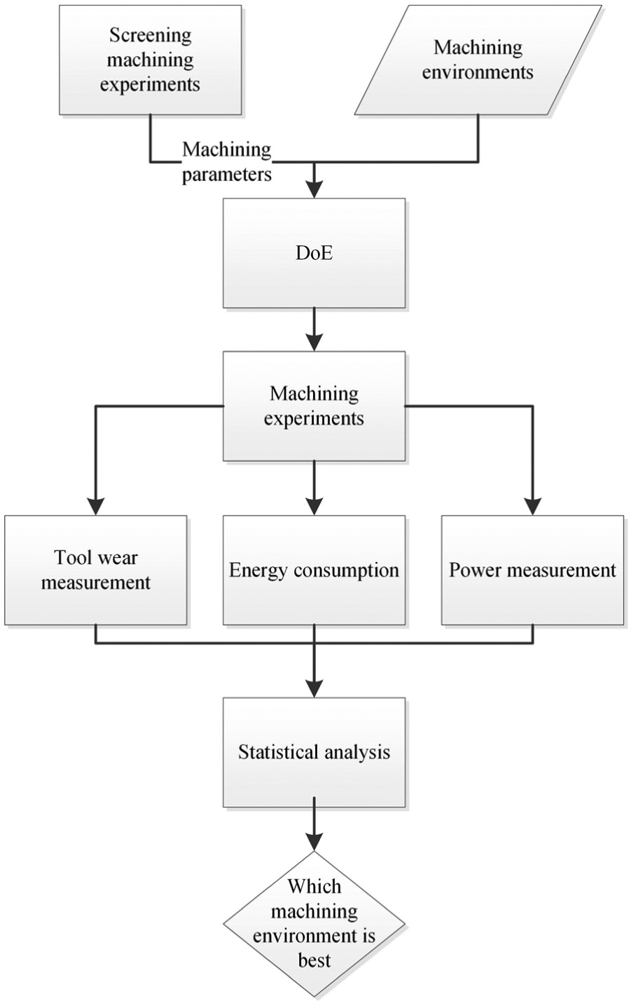
Methodology for empirical investigation.
The investigations were based on comparing the effects of cryogenic cooling with conventional dry and flood cooling. The machining experiments were end-milling operation using solid carbide cutting tools and were repeated three times to ensure repeatability of the process. An intact 12-mm-diameter solid tungsten carbide cutting tool with 3 flute and TiN-TiAlN coating with 12° rake angle and 38° helix angle was used for each machining experiment.
In order to investigate the effect of cryogenic cooling and fully capture the effect of various parameters, a hybrid design of experiment (DoE) was developed for experimentations, as illustrated in Figure 2. Cutting speed, feed rate and depth of cut were identified as the major cutting parameters affecting the machining performance in end-milling operations. 46 Therefore, in this DoE, an L9 orthogonal array was used to generate a meaningful combination of cutting speed, feed rate and depth of cut. Three levels of maximum, minimum and medium were used for each parameter to generate the L9 DoE.
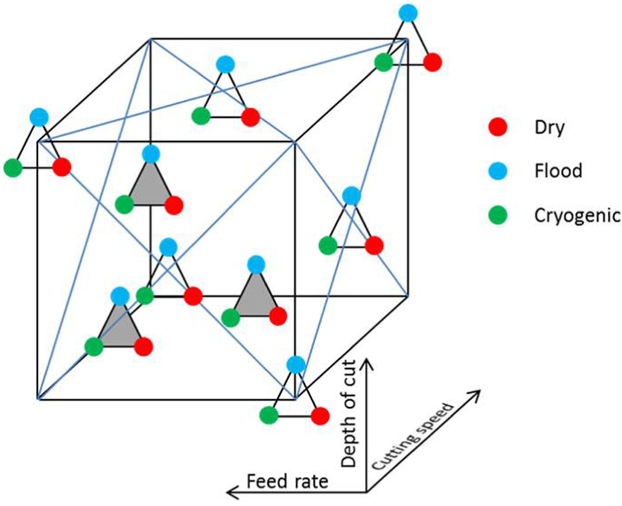
L9 design of experiment with repetition for dry, flood and cryogenic cooling machining environments.
As shown in Figure 2, to include machining environment for the experiments, the L9 DoE was repeated three times under dry, flood and cryogenic cooling environments. The levels for each machining parameter were based on initial screening experiments47–49 and the machine tool’s and cutting tool’s capabilities.
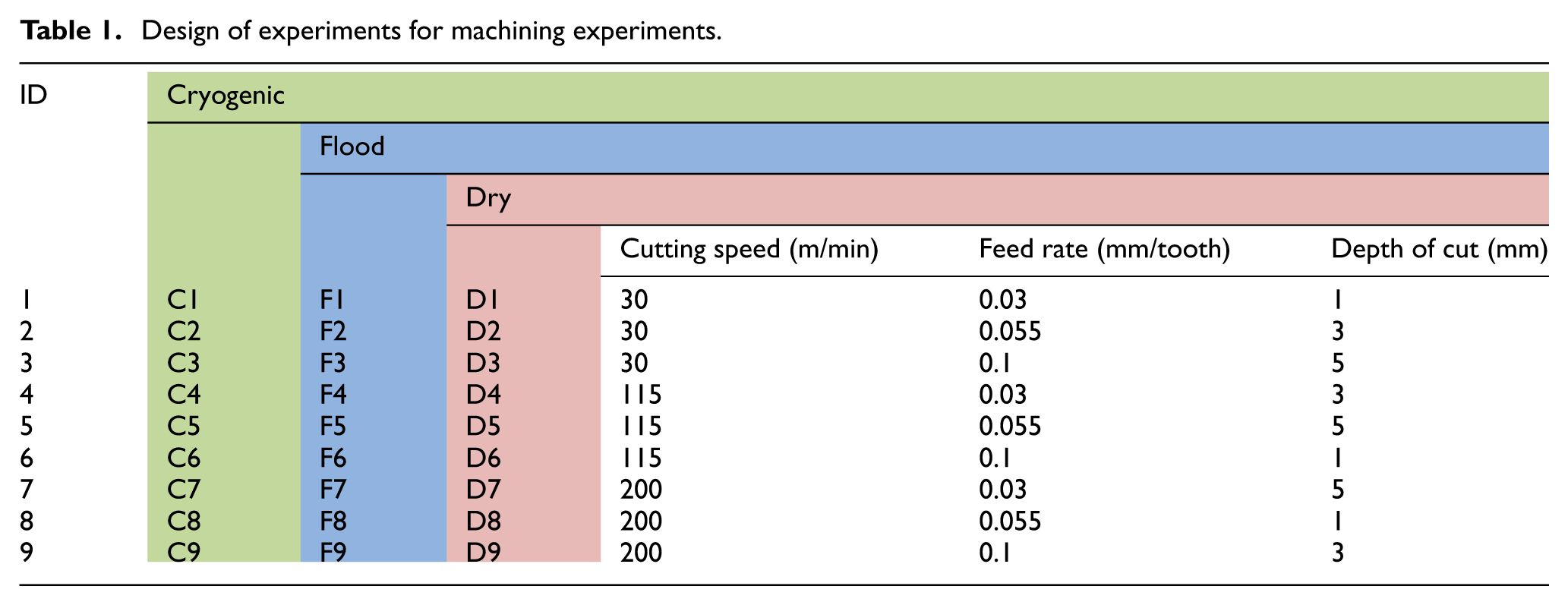
Table 1 demonstrates the detailed hybrid L9 × 3 DoE used for this investigation. Using this DoE, the machining environments are compared using a full factorial method while the effects of cutting parameters are also taken into account using L9 orthogonal array. Each machining experiment was repeated three times to ensure repeatability. Based on BS ISO 5725-1:1994 50 and BS ISO 5725-3:1994, 51 in the context of precision measurement, many factors (e.g. operator, equipment, environment and time) may affect the accuracy and correctness of the measured results. Therefore, the recommendations of these standards were strictly followed throughout the experimentation and measurement.
Design of experiments for machining experiments.
The machining experiments were conducted on a Bridgeport VMC 610 vertical computer numerical controlled (CNC) milling centre. For flood cooling experiments, water-miscible cutting fluid with extreme pressure additives at 8% concentration was used as recommended by the supplier. A cryogenic cooling nozzle was designed and built in-house for cryogenic machining experiments.48,49 Figure 3 demonstrates a schematic view of the system. The nozzle was designed to spray a minimum amount of liquid nitrogen (LN2) at −196°C and 1 bar along the cutting tool into the cutting zone based on screening experiments and as identified by Shokrani et al. 49 As shown in Figure 3, the LN2 is supplied through a self-pressurised Dewar which eliminates the requirements for an external power supply.
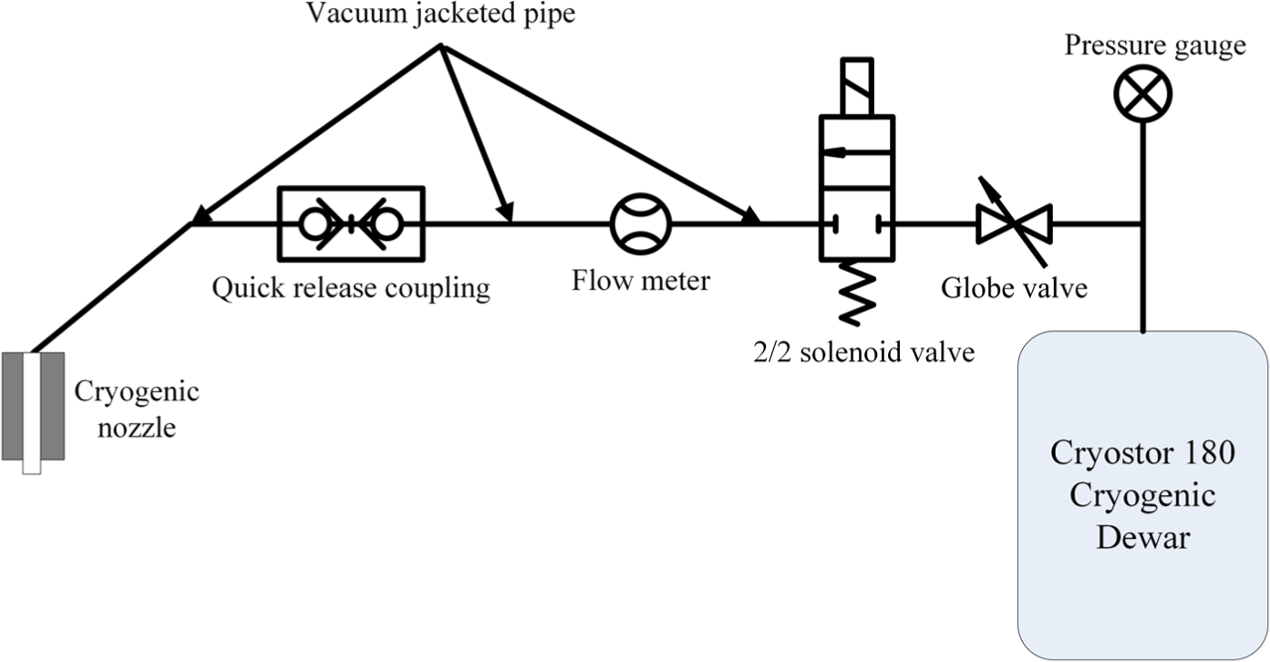
Schematic view of the cryogenic cooling system used for cryogenic machining. 49
A block of annealed Ti-6Al-4V alloy with dimensions of 50 mm × 50 mm × 150 mm was supplied for each machining experiment. The average hardness of the blocks was 285% ± 5% HV which was measured using a Vicker’s hardness tester.
The machining experiments consisted of 4 mm × 150 mm straight side milling along the test piece blocks. The tool overhang was kept constant for all experiments to minimise the variations due to tool deflection. The power consumption of the machine tool was monitored during the experiments using a Hioki Clamp on Hi-tester 3169-20 power demand analyser which was wired into the machine tool.
The energy consumption of the machine tool and the specific machining energy were calculated from the machine tool’s power consumption using equations (2) and (3), respectively 52
where E is the energy in joules, P is the power in watts, V is the volume of machined material in mm3, t0 is the time in seconds when cutting tool engages with the material and t is the time in seconds when the cutting tool leaves the material.
After the machining experiments were conducted, the cutting tool was dismounted and cleaned by acetone. The cleaned cutting tool was then examined under a tool maker’s microscope equipped with a high-resolution digital camera. The tool wear was measured following the instructions provided by ISO 8688-2:1989, 53 and all tool wear phenomena, for example, chipping and notching, were treated as flank wear for comparison.
Results and analysis
The results from machining experiments are presented and analysed below. Moreover, the effect of the machining environment on tool life, power consumption, energy consumption and specific machining energy are further investigated.
Tool wear
After conducting the machining experiments, the flank wear of the cutting tools was measured for each experiment. The average tool wear results of the experiments are provided in Figure 4. The results indicated that in most cases, cryogenic cooling produced the lowest tool wear as compared to dry and flood cooling. Adversely, on average, the highest tool wear was detected on the tools used in dry environment.
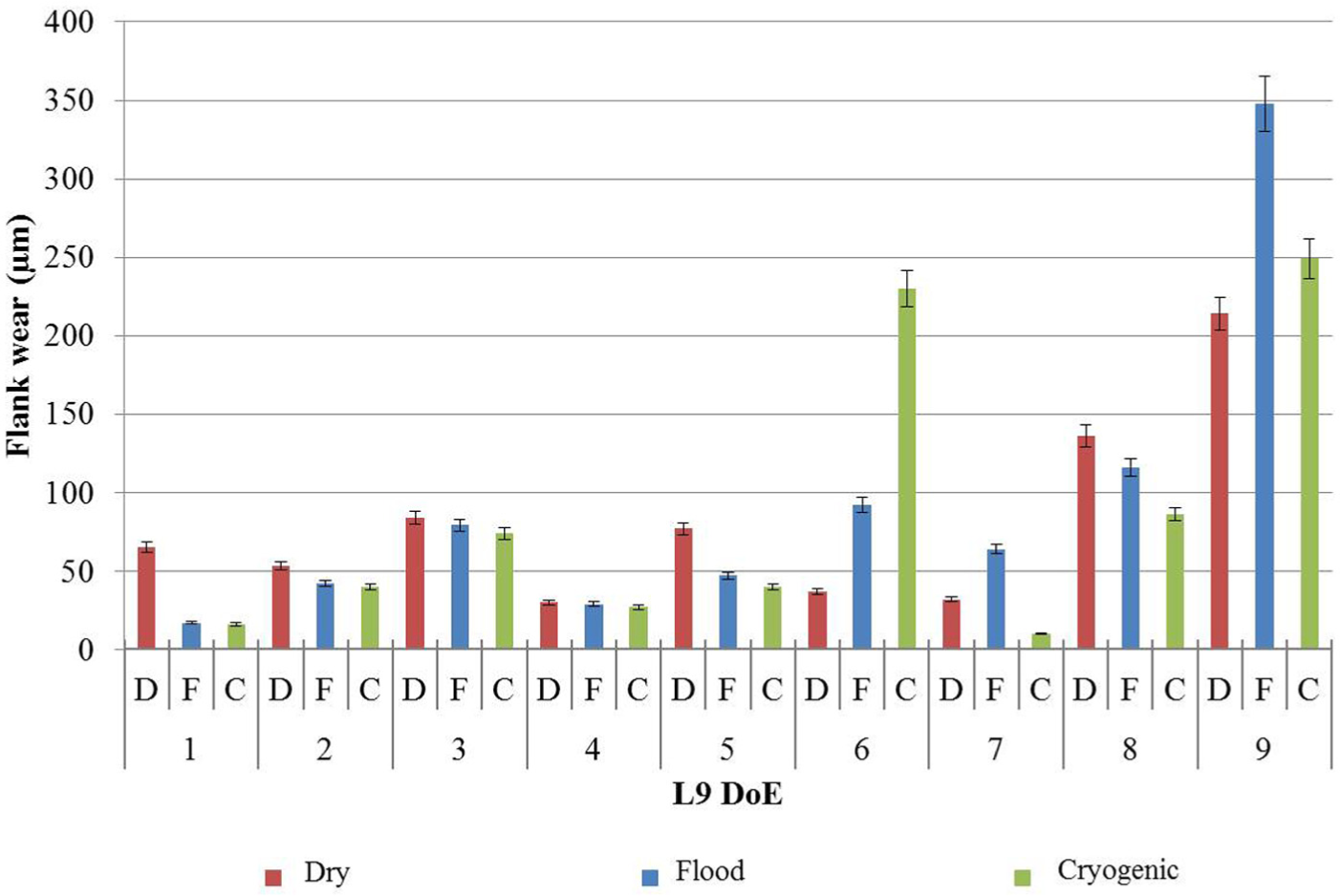
Tool wear for each machining experiment.
As illustrated in Figure 4, increasing the feed rate has a significant effect on tool wear which is irrespective of machining environment. Furthermore, the data for tool wear indicate that cutting speed significantly intensifies the effect of feed rate on tool wear. As shown in Figure 4, comparison of the measurement results for tool wear revealed that the smallest flank wear in cryogenic machining is associated with experiment C7 (10 µm), while they are W1 (17 µm) and D4 (30 µm) for wet and dry machining, respectively. From this, it can be concluded that lower tool flank wear can be expected in cryogenic machining while increased productivity can be achieved as a result of higher cutting speed in comparison with dry and wet machining.
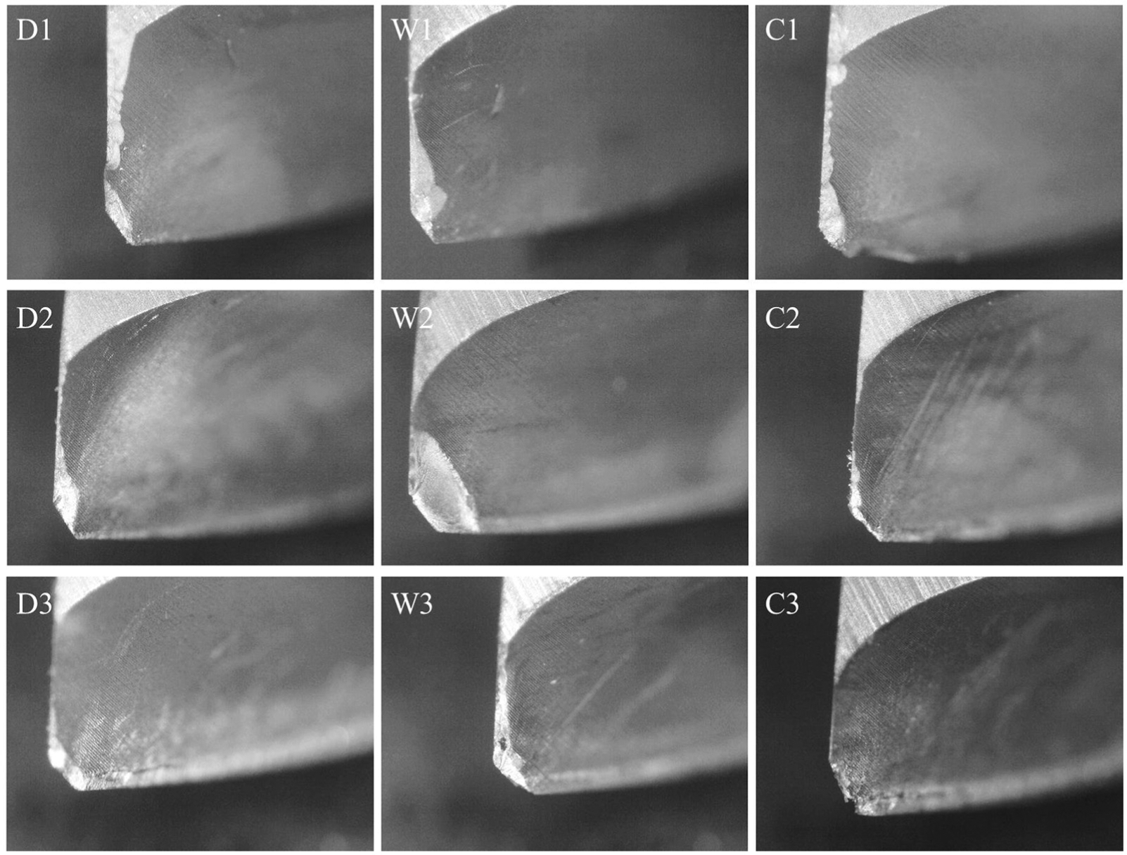
The second lowest tool wear was also attributed to the tool used under cryogenic cooling for experiment C1 at 30 m/min cutting speed, 0.03 mm/tooth and 1 mm depth of cut. Analysis of the micrographs of the cutting tool, illustrated in Figure 5, indicates that the mechanical tool wear mechanisms, for example, abrasion and chipping, are dominant at lower cutting speeds and feed rates. In contrast, thermomechanical and chemical phenomena such as attrition, crater wear and adhesion were observed at higher cutting speeds and feed rates. For instance, while abrasion was the dominant tool wear mechanism for D1, W1 and C1 (Figure 5), smearing and adhesion can be seen for the tools D9, W9 and C9. Moreover, smearing on the flank face was detected on the cutting tools which are more profound at lower cutting speeds.
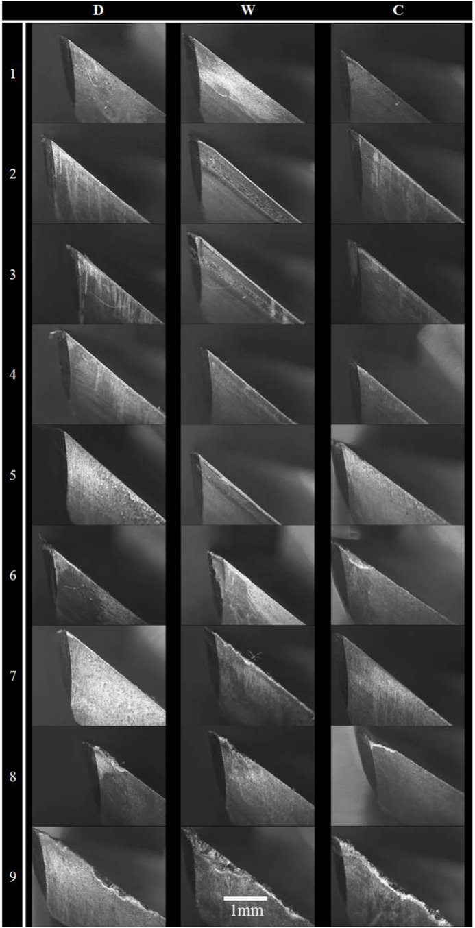
Micrographs of the cutting tools used for machining experiments.
The tools used for experiment 9 showed the highest tool wear across all machining environments. As explained in the methodology, the maximum level of cutting speed and feed rate was used for experiment 9. Thermomechanical wear mechanism was dominant for all cutting tools in experiment 9. The tool wear was initiated by crater wear and chipping of the cutting edge and was followed by attrition and abrasion. As shown in Figure 5, significant chipping on the rake face and attrition and abrasion wear on the flank face resulted in tool failure in experiment 9. It is noteworthy to mention that catastrophic failure occurred for two of the cutting tools used for experiment D9 and the cutting tools failed prematurely before reaching the 600 mm machining length. Therefore, the value shown in Figure 4 for tool wear is only representative of one experiment.
Unlike the flank face, the rake face is not in direct contact with machined surface. However, welding and formation of built-up edge on the rake face have the potential of weakening the cutting edge by making crater wear. As shown in Figure 6, flaking, crater wear and formation of built-up edge were dominant for all machining experiments irrespective of machining environment. It has been noticed that the crater wear formed a narrow line adjacent to the cutting edge on all the cutting tools.
Flaking and crater wear on the tools used in machining experiments.
Constant flow of the chips over the rake face removes material from the cutting tool adjacent to the cutting edge and forms crater wear. This potentially weakens the cutting edge resulting in chipping and tool failure. As illustrated in Figure 6, cryogenic cooling significantly reduced the severity of this phenomenon showing the potential to improve the tool life.
Power consumption
The power consumption of the machine tool was monitored at a sampling rate of 1 Hz during the machining experimentations. Figure 7 illustrates an example of the power consumption of the Bridgeport VMC 610 machine tool with and without using coolant pump. The power consumption graph shown in Figure 7 can be categorised into eight distinct areas illustrated under the graphs. In region 1, the machine is turned on and the emergency stop button is pressed. Releasing the emergency stop (region 2) will result in activating the machine’s drives and therefore increasing the machine tool’s power consumption from 470 to 870 W in idle mode. In the third region, the coolant pump was turned on for flood machining graph for 50 s. As shown in Figure 7, there is a peak at the start of the graph indicating inrush for the coolant pump motor. On average, the coolant pump adds 800 W to the total machine tool’s power consumption independent of cutting parameters. At the end of the third region, the coolant pump was turned off for 50 s (region 4). Since no coolant pump is used for dry machining, the power consumption of the machine tool was identical in the third, fourth and fifth regions for dry cutting graph. The coolant pump was turned on at the start of region 5 and the machine was set for machining. Following the process plan, at the end of region 5 and start of region 6, the spindle was turned on and the cutting tool moved to the start position for machining with rapid move. This together with the spindle motor’s inrush has resulted in a sharp peak in region 6. Afterwards, the cutting tool moves with feed towards the workpiece material. In region 7, the cutting tool engages with workpiece material resulting in increased power consumption. When the cutting tool exits the workpiece at the end of region 7, the move with feed continues for 10 s, the spindle and coolant pump stop and the power consumption graph plunges back to the idle mode.
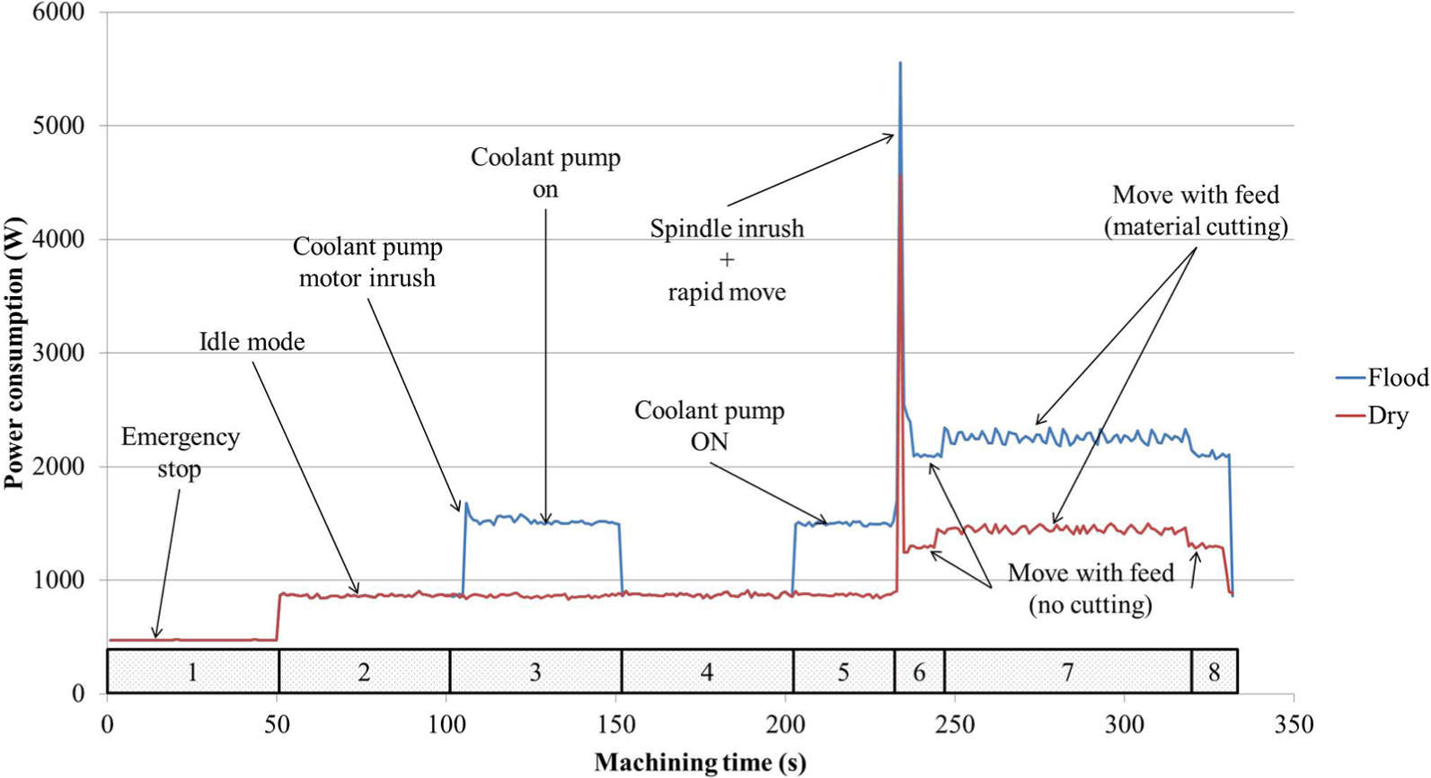
Example power consumption graphs of CNC milling process.
In order to identify the effect of various cutting parameters and machining environment on power consumption, the power consumption of the none-material cutting moves, for example, idle mode, rapid movement, plunging and move with feed without material cutting were isolated. Furthermore, in order to remove the noise from the measurements, a Gaussian filter was applied on the measured results. Salonitis 13 and Salonitis and Ball 5 found that the peripherals of the machine tool, for example, coolant pump, lubricant pump and controller, have constant power consumption which is not affected by cutting parameters. Therefore, they suggested that the monitoring procedure has to be designed in a way to be able to detect and consider these elements for power consumption. In this study, the idle power consumption of the machine was identified to be constant irrespective of the machine tool’s state. Furthermore, the power consumption for coolant pump and rapid move was constant.
The average power consumption of the machine tool was then calculated for each machining experiment. As shown in Figure 8, the power consumption of the machine tool is distinctly higher for all experiments conducted under flood cooling. This is due to the average 880 W power consumption of the machine tool’s coolant pump. Analysis of the means for the power consumption indicated that the lowest power consumption was attributed to dry machining as illustrated in Figure 9.
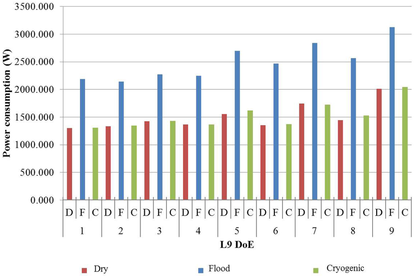
Power consumption of the machine tool for each machining experiment.
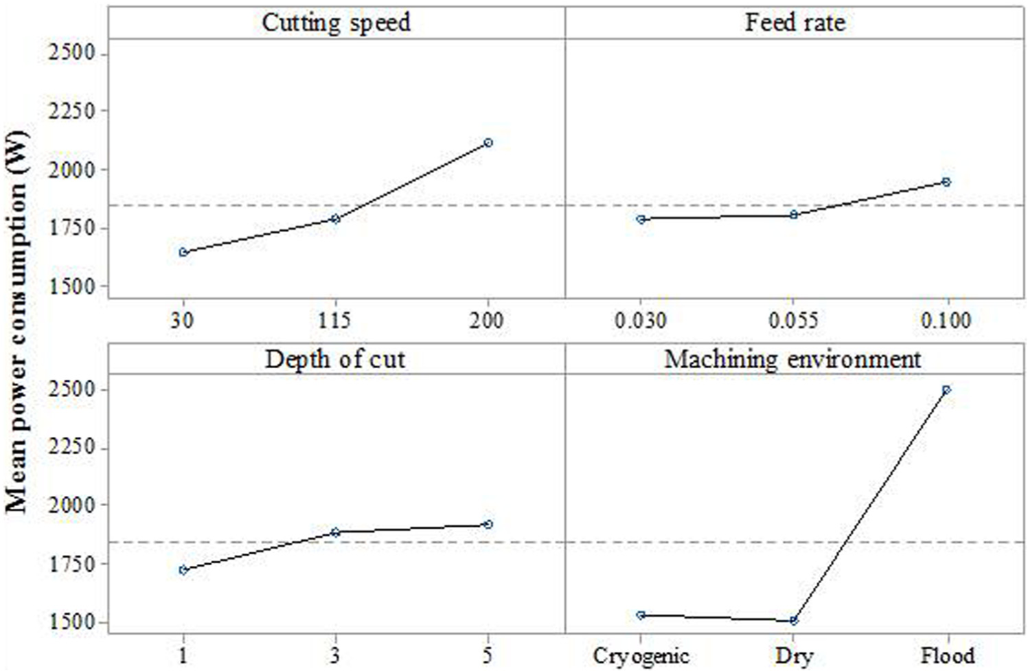
Analysis of means for power consumption.
On average, the power consumption in cryogenic machining was 1.5% more than that of dry machining. This can be due to the increased material hardness at extremely low cryogenic temperatures as stated by Hong and Zhao. 40 As shown in Figure 10 (top), the histogram of power consumption for machining environments indicated that the measurement results are skewed towards flood cooling. Therefore, 880 W was deduced from the power consumption of the experiments in flood cooling to isolate the effect of coolant pump on the power consumption. Analysis indicated that the effect of machining environment where coolant pump’s power consumption is isolated is not statistically significant.
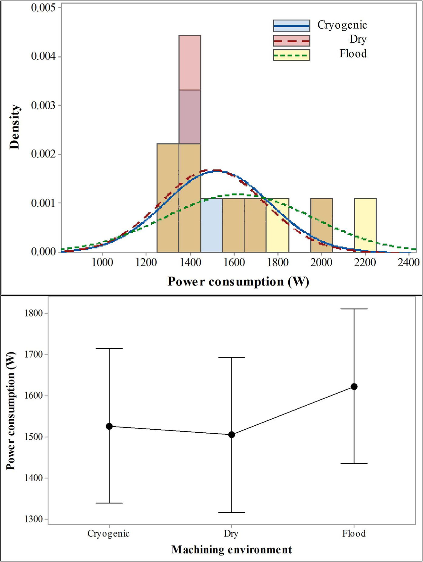
Histogram of power consumption using dry, cryogenic and flood cooling (top) and mean power consumption of various machining environments when coolant pump’s power consumption is isolated (bottom).
As shown in Figure 10 (bottom), while the average power consumption in flood cooling is higher than that of dry and cryogenic machining, the wide range of measurement results (standard deviation) does not confirm a statistically significant difference between the means.
Furthermore, the analysis of means, shown in Figure 9, suggests that lower levels of cutting speed, feed rate and depth of cut should be used in order to reduce power consumption in milling operations. Although it seems logical to reduce the rotational speed of the machine tool’s spindle and axes and reduce the torque by choosing lighter depth of cut, this would significantly affect the productivity and material removal rate. Moreover, while the power consumption is a useful guide for choosing the right equipment (spindle power, axes motors, etc.) for machining, it does not necessarily reflect the amount of energy required for machining a component.
Energy consumption and specific machining energy
As explained in the methodology, energy is the integration of power consumption over time and evidently, it is significantly affected by the machining time. For this investigation, the energy consumption of the machine tool was calculated for each machining experiment from the power consumption and is illustrated in Figure 11. Moreover, the specific machining energy was calculated to indicate the amount of energy used by the machine tool for cutting a unit volume (1 mm3) of Ti-6Al-4V as demonstrated in Figure 12.
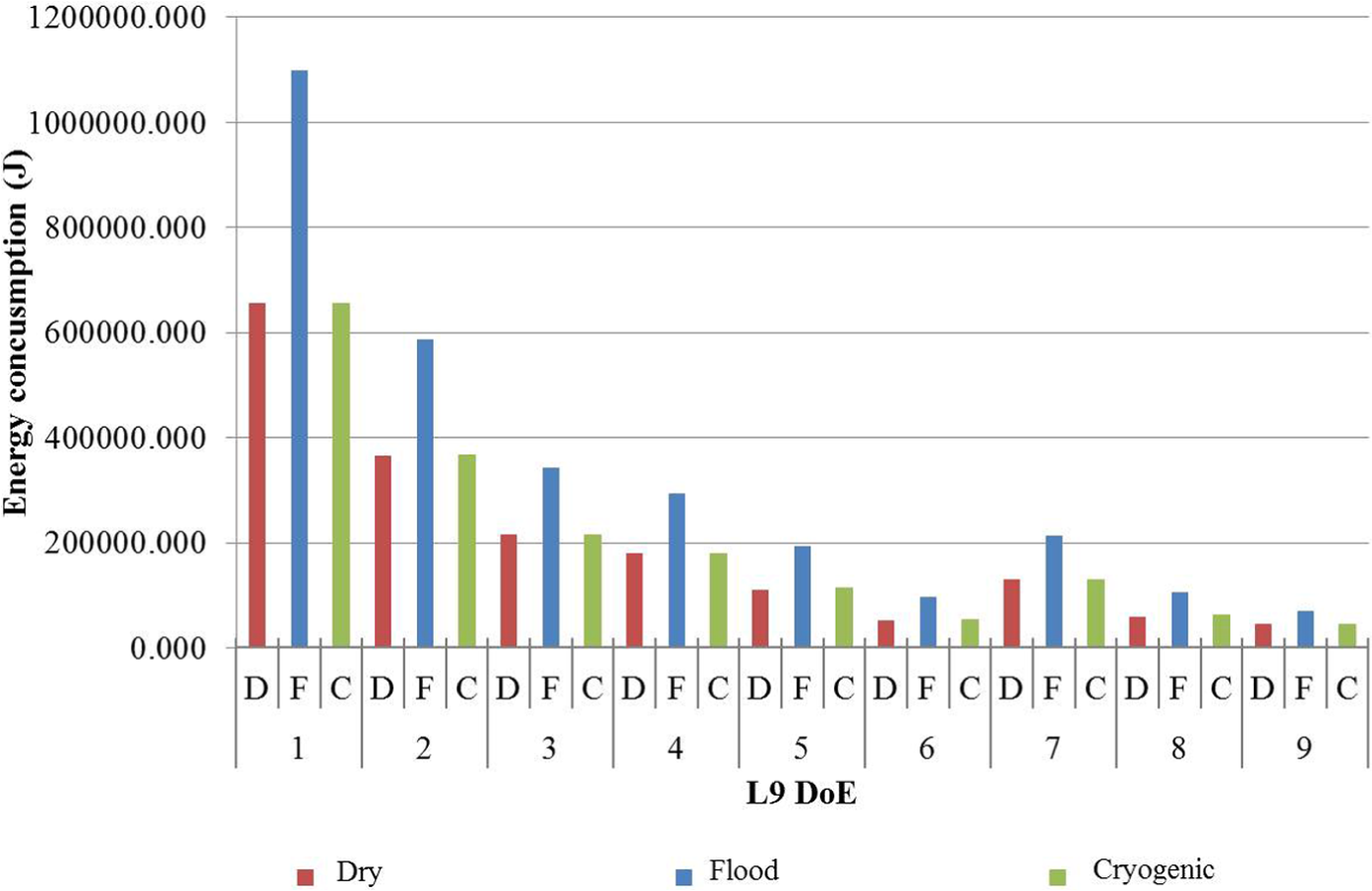
Energy consumption of the machine tool during each machining experiment.
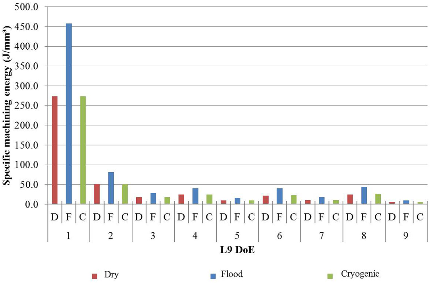
Specific machining energy for each machining experiment.
As shown in Figure 11, increased material removal rate through using higher cutting speeds and feed rates has significantly reduced the energy consumption and specific machining energy. Since the machining time for similar experiments under different machining environment is identical, similar conclusions to the power consumption can be drawn for the effects of machining environment on energy consumption. The analysis shows that flood cooling is the least favourable machining environment mainly due to the significant energy consumption of the coolant pump. As shown in Figure 13, the Boxplot graphs indicated that the average energy consumption is higher for flood cooling while there is no significant difference between dry and cryogenic machining. Moreover, the Boxplot graphs indicated the existence of outliers and skewness in the measurement results.
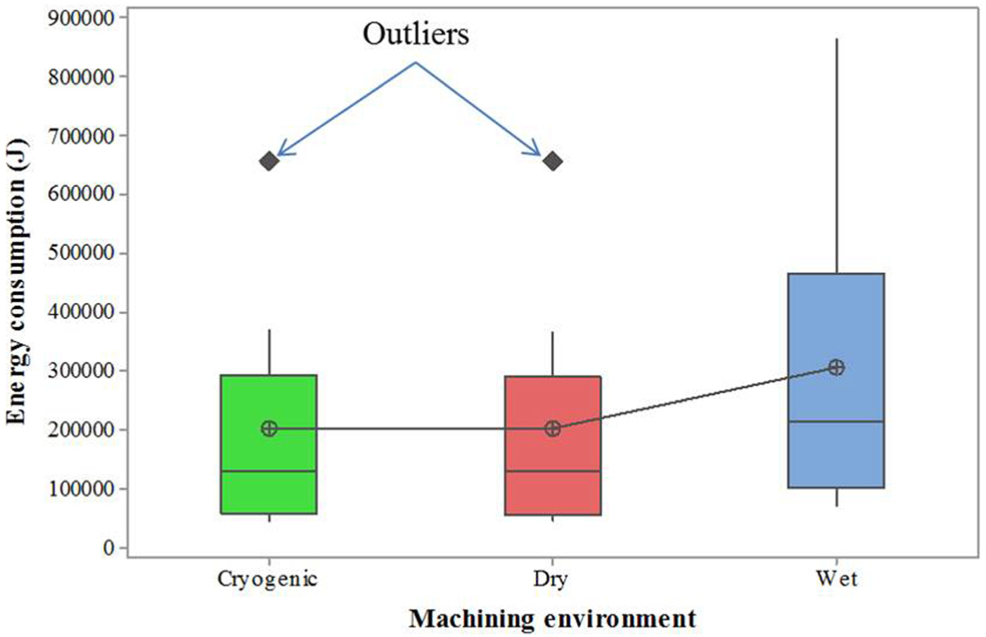
Boxplot graphs of energy consumption for machining environment.
Therefore, the signal-to-noise (SN) ratio of the results using equation (4), smaller-is-better, was used for the analysis as recommended by Xin 54

where for experiment Y, y is the measured values and n is the sample size.
Analysis of mean SN ratio graphs, as shown in Figure 14, indicated that higher levels of cutting speed and feed rate have the largest mean SN ratio and therefore are more favourable. The analysis indicated that the effect of depth of cut on the energy consumption is not as significant while lighter depths of cut are more favourable. By definition, it can be understood that the higher the cutting speed and feed rate, the higher material removal rate and hence shorter machining time. Therefore, lower energy is required for machining the test piece material. In contrast, higher depths of cut induce more torque on the spindle and axes motors resulting in higher energy consumption.
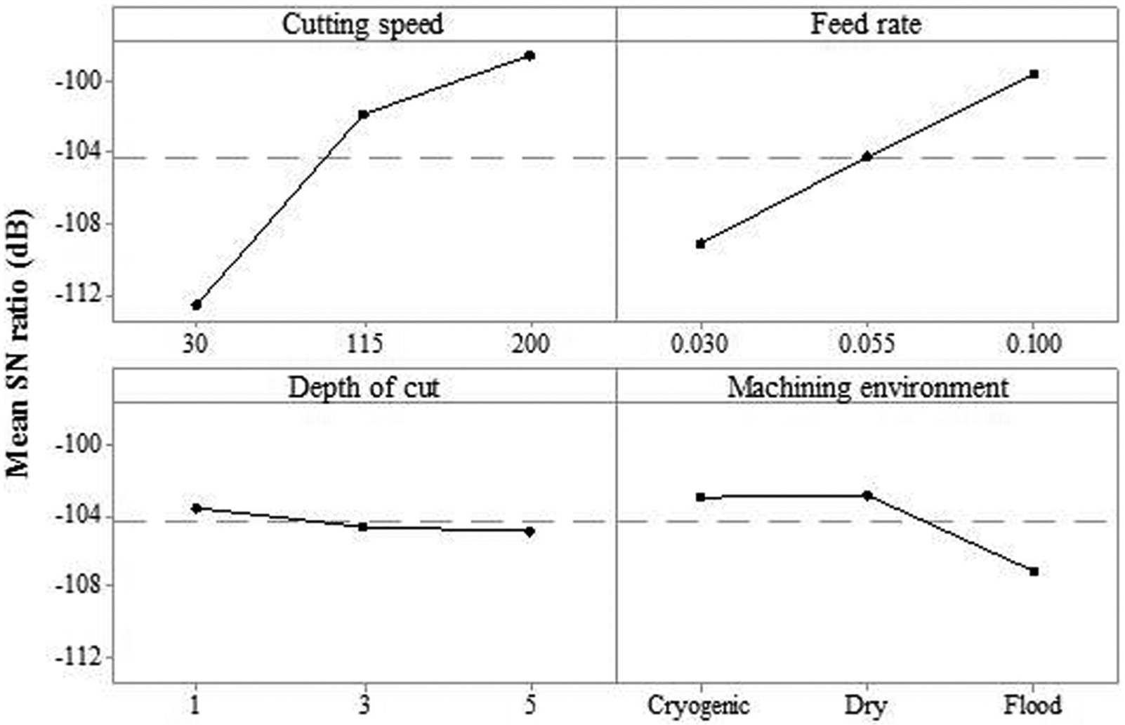
Mean SN ratio graphs of energy consumption.
The analysis of specific machining energy (Figure 12) demonstrated that experiment 1 has the highest specific machining energy while increasing cutting parameters significantly reduces the specific machining energy. As shown in Figure 15 (left), the Boxplot graph of the specific machining energy for machining environment indicates that the specific machining energy is not significantly affected by machining environment. As explained previously for power and energy consumption, the use of coolant pump resulted in higher specific machining energy for experiments conducted under flood cooling. Isolating the coolant pump energy consumption from the analysis, it was revealed that the effect of machining environment on the specific machining energy is very limited as shown in Figure 15 (right). Furthermore, it was found that all groups contain outliers which necessitate SN ratio analysis.
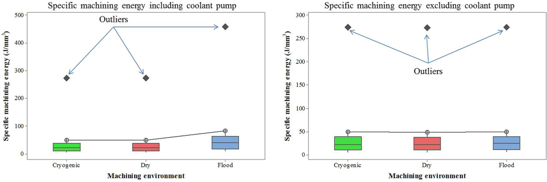
Boxplot graphs of specific machining energy including the coolant pump (left) and excluding the coolant pump (right) power consumption.
The SN ratio analysis of the data for specific machining energy, illustrated in Figure 16, indicated that the higher levels of cutting speed, feed rate and depth of cut have the highest mean SN ratio and therefore are most favourable for reducing the amount of energy required for machining a unit volume of Ti-6Al-4V material. Dry and cryogenic machining demonstrated almost equal mean SN ratio and are more favourable than flood. The analysis revealed that increasing material removal rate through utilising higher cutting speeds, feed rates and depths of cut is the most convenient way of minimising specific machining energy. This way, the total energy consumption for machining a part will also be minimised.
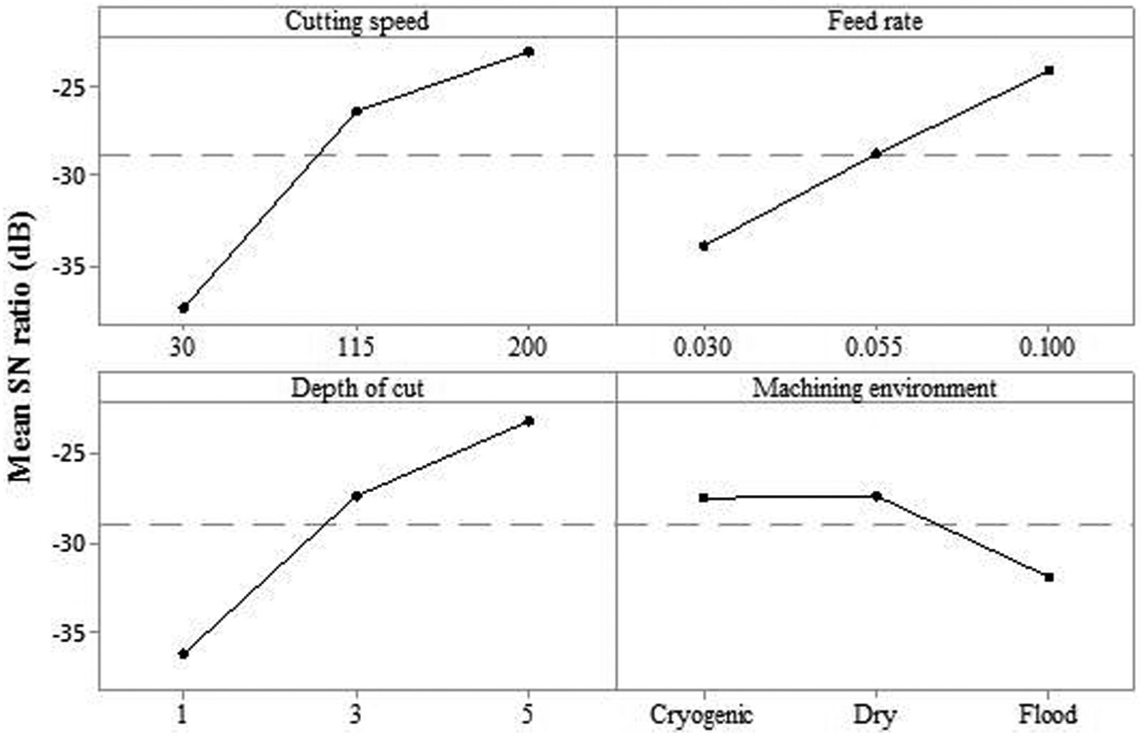
Mean SN ratio graphs of specific machining energy for input parameter.
Discussion
Analysis of the cutting parameters and machining environment indicated that cryogenic machining is the best way to minimise tool wear and therefore improved tool life in machining Ti-6Al-4V titanium alloy. Bordin et al. 55 and Venugopal et al.56,57 reported that cryogenic cooling considerably reduced tool wear in turning Ti-6Al-4V workpieces. Specifically, the authors found that cryogenic cooling restricted the adhesion wear on both rake and flank faces. Similarly, limited crater wear was observed on the rake face as compared to dry machining. This is in agreement with the findings of this research in cryogenic CNC milling where the tools used for cryogenic machining had lower crater wear as compared to their counterparts used for machining in dry and flood cooling.
As shown in Figure 17, the Ti-6Al-4V alloy used in this study consists of alpha-titanium phase with hexagonal close-packed (hcp) structure and beta phase with body-centred cubic structure (bcc). In Figure 17, the alpha-titanium plates appear darker and beta-titanium boundaries are shown in brighter colour. The deformation of metals takes place by sliding (slip) of closed pack planes in the crystal structure. An ideal hcp structure with c/a ratio of 1.633 has three slip systems along its (0002) basal planes in the direction of
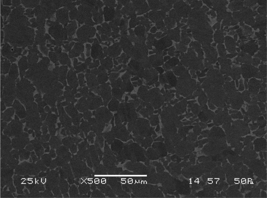
SEM micrograph of the Ti-6Al-4V titanium alloy used in this research.
As shown in Figures 18 59 and 19, 60 reducing the material temperature to −196°C significantly reduces the percent elongation and fracture toughness of Ti-6Al-4V alloy, respectively. This, in turn, facilitates material cutting, reduces tool wear and allows for employing higher cutting speeds. Furthermore, the investigations revealed that using a cryogenic environment at −196°C facilitates heat removal from the cutting zone and reduces chemical affinity between cutting tool and workpiece materials enabling using higher cutting speeds.
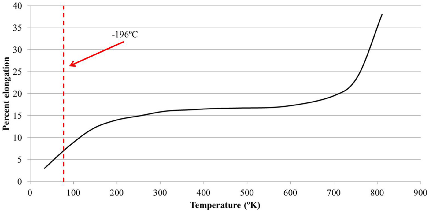
Percent elongation versus temperature graph of Ti-6Al-4V.

Fracture toughness versus temperature graph of Ti-6Al-4V. 60
For instance, the lowest tool wear occurred on the tool used in experiment 7 at 200 m/min cutting speed. Similar observations have been reported by Hong and Broomer 30 and Kalyan Kumar and Choudhury 61 in turning operations. Hong et al. 62 stated that in turning operations, at high cutting speeds of 150 m/min, the cutting tools failed prematurely under flood cooling while five times improvement was achieved using cryogenic machining. The authors noted that the improvement in tool life is more significant at higher cutting speeds. Similar observations are reported by Khan and Ahmed. 63
The analysis for power consumption indicated that a significant amount of energy is used for coolant pump in the machine tool. This has made flood cooling the least favourable machining environment from power and energy consumption point of view. Based on the experimental results, the coolant pump accounted for 36%–44% of the total power consumption of the machine tool. Similar observations were reported by Gutowski et al. 8 that 85.2% of the machining power consumption is constant even if the machine is idle. The researchers 8 attributed this to the pumping of coolant, lubricant and hydraulic fluids. Aggarwal et al. 64 conducted a series of comparative machining experiments to identify the effect of cryogenic cooling in turning of AISI P20 steel. In their research, machining environment, cutting speed and depth of cut were found to be the most significant parameters affecting power consumption. They identified the elimination of coolant pump’s power consumption as a result of dry and cryogenic machining as an underlying reason for the significance of machining environment for power consumption. Moreover, although cryogenic cooling has increased the hardness of AISI P20 steel by 10%, the researchers found that cryogenic cooling has resulted in lower power consumption than dry machining. They attributed this reduction to the reduced cutting temperature and therefore machining stress and cutting forces. 65 In contrast, the investigations, detailed in section ‘Power consumption’, indicated that that cryogenic cooling resulted in 1.5% increase in power consumption as compared to dry machining. Hong et al. 66 stated that cryogenic cooling produced higher cutting forces than dry machining in turning of Ti-6Al-4V. They attributed this rise to the increased material hardness and strength as a result of cryogenic temperatures.
In order to minimise the energy consumption of a machine tool, higher levels of cutting speed and feed rate are desired. This is mainly due to the fact that the amount of energy required for running the machine tool is significant. 8 Fratila 67 noted that in machining 16MnCr5 alloyed steel, the amount of energy used for cutting material is 45% less than the actual machine tool’s energy consumption. Therefore, reducing the machining time can significantly reduce the energy consumption. The experiments clearly showed that employing 200 m/min cutting speed is possible using cryogenic cooling which results in almost seven times reduction in machining time. As shown in Figure 20, Li et al. 7 reviewed the energy consumption of various machine tools and noticed that on average, only 17% of the total machine tools’ energy consumption is due to the servo drives. In contrast, on average 31% of the machine tools’ energy consumption is associated with coolant/lubricant system which is close to the 40% increase in energy consumption in flood cooling found in this research (see section ‘Energy consumption and specific machining energy’).
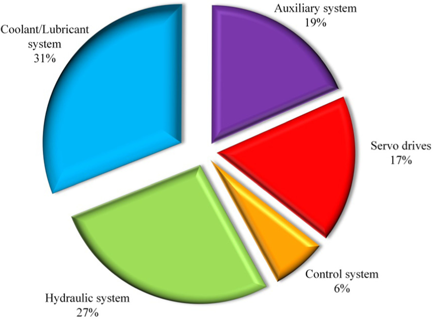
Energy consumption breakdown of a machine tool.
The most important parameter for energy-efficient machining, however, is the specific machining energy as it defines the amount of energy required for machining a specific part. Helu et al. 68 claimed that one way of achieving sustainability and reducing resource cost is to increase the cutting speed and the depth of cut. However, it is noted that this may deteriorate the cutting tool faster and hence not applicable.21,68 The analysis of the data detailed in section ‘Results and analysis’ indicated that increasing material removal rate using higher values for cutting speed, feed rate and depth of cut is the most effective way of minimising specific machining energy. Since titanium is notoriously considered a difficult-to-machine material, employing higher cutting speeds and feed rates is generally not applicable, using conventional machining techniques. 24 As demonstrated in experiment 7, cryogenic cooling has shown promising potentials for allowing using higher values of cutting speed (200 m/min) and therefore increased material removal rate and lower specific machining energy. Comparison between the experiment C7 and F1 indicates that seven times increase in cutting speed has resulted in about 88% reduction in energy consumption while increasing the productivity by seven times. Despite this, for sustainable manufacturing, the energy consumption for preparing liquid nitrogen and preparation, maintenance and disposal of water-miscible cutting fluid together with the environmental impact of manufacturing cutting tools should be considered.
Conclusion
A systematic methodology was developed to investigate the effects of cryogenic cooling in machining Ti-6Al-4V and investigate the power consumption, energy consumption and specific machining energy in end-milling operations. Based on the experimental results and analysis, the following conclusions were drawn:
The investigations indicated that cryogenic cooling is the most favourable machining environment to minimise tool wear in end milling Ti-6Al-4V while eliminating the use of hazardous water-based cutting fluids.
The 12-mm-diameter coated solid carbide cutting tool used for cryogenic machining at 200 m/min cutting speed, 0.03 mm/tooth feed rate and 5 mm depth of cut possessed the lowest tool wear among all combinations of cutting parameters and machining environments.
This study indicated that mechanical tool wear phenomena, such as chipping and abrasion, are dominant at lower levels of cutting speed and feed rate. Increasing the cutting speed and feed rate resulted in thermal and mechanical tool wear mechanisms such as adhesion, built-up edge and crater wear.
The coolant pump of the machine tool consumes a significant portion of the machine power making dry and cryogenic cooling the most favourable machining environments for minimising power consumption. The analysis revealed that on average 40% of the power consumption in flood cooling is attributed to the coolant pump. Introducing the workpiece material to cryogenic temperatures results in an increased material hardness and therefore 1.5% increased power consumption in comparison to dry machining.
Increasing material removal rate is necessary for minimising specific machining energy. However, tool life is a limiting factor for realisation of higher material removal rates through increased cutting speed, feed rate and depth of cut. Using cryogenic cooling, the material removal rate of more than 9500 mm3/min with minimum tool wear was achieved. Through increased material removal rate, cryogenic cooling has shown significant potential to minimise specific machining energy.
Cryogenic cooling allowed for a sevenfold increase in cutting speed and productivity while 88% energy saving was achieved. This indicates the significant potential of cryogenic cooling for revolutionising machining of titanium alloys.
Footnotes
Declaration of conflicting interests
The author(s) declared no potential conflicts of interest with respect to the research, authorship and/or publication of this article.
Funding
The author(s) disclosed receipt of the following financial support for the research, authorship, and/or publication of this article: The authors would like to acknowledge the industrial partners for supporting this research.