
Abstract
Most of the early five-axis computer numerical control systems do not have the function of five-axis tool length compensation. When the tool length changes in five-axis machining, the original numerical control program will not be able to continue to be utilized. At the moment, the cutter location file needs to be post-processed again to generate the new numerical control program through modifying the value of the pivot length. In order to solve the above problem, this article proposes a five-axis tool length compensation method using the numerical control program with macro variable for five-axis machine tools with dual rotary heads or with a rotary head and table. First, by analyzing the structure of the specific five-axis machine tool, a kinematics model of the five-axis machine tool was established and solved. Second, a post-processor for the five-axis machine tool was developed, and the pivot length as a macro variable was written into the numerical control program through the post-processor. Moreover, the five-axis tool length compensation was implemented by modifying the macro variable of pivot length in the numerical control program. Finally, a turbine blade was machined on a five-axis machine with a rotary head and table, the generated cutter location file was converted into the numerical control program with macro variables by using the proposed method, and the generated numerical control program was simulated on the solid cutting simulation software. Simulated results verify the effectiveness of the proposed method. In addition, the proposed method can be widely applied to early five-axis machine tools without the function of five-axis tool length compensation.
Keywords
Introduction
The tool length compensation is one of the important functions for the modern computer numerical control (CNC) system. In three-axis CNC machining, when tool length changes (e.g. tool wear or tool replacement), the CNC system can implement the function of tool length compensation by modifying the value of tool length in the CNC system registers (such as G43 and G44). At the moment, the original NC program can still be used. 1 However, in five-axis NC machining, it is relatively difficult to implement the tool length compensation due to the continuous change in tool orientation. 2 At present, famous foreign CNC system companies have developed five-axis CNC systems with the function of tool length compensation (i.e. rotate around tool center point (RTCP)). For example, the standard configuration of five-axis CNC system from Siemens Company does not contain the function of five-axis tool length compensation, but you can enable this function through purchasing a five-axis function package. 3 Therefore, the cutter location (CL) data file can be post-processed to generate the NC program by using the generalized five-axis post-processor or the built-in post-processor of computer-aided design (CAD)/computer-aided manufacturing (CAM) software.4–9
Many scholars have also done a lot of research work on five-axis tool length compensation. Tang and Bian 10 analyzed the basic principle of tool length compensation in five-axis machining and gave parameter setting and application of the Siemens CNC system with five-axis tool length compensation function. Chen and Wang 2 analyzed the difference between the spindle programming and the RTCP programming, and derived the calculation equations of tool length compensation. Liang and Wang 11 analyzed the RTCP function of five-axis CNC system and derived the equations of RTCP function. Fan et al. 12 proposed a new design of interpolated algorithm integrated with RTCP function based on detailed analysis of the kinematics principle of five-axis machine with dual rotary tables. Hu et al. 13 introduced a new real-time compensation RTCP module theory to meet the goal of high-precision compensation and the reasonable use of traditional resources.
However, many corporations still have some early five-axis CNC machine tools in the practical application, which do not have the function of five-axis tool length compensation. Hence, when tool length changes in five-axis machining, the original NC program will not be able to be reused. At this moment, the value of tool length needs to be modified, and the original CL file is then post-processed to generate the new NC program with the commercial post-processor (such as post builder of Unigraphics (UG)). The above approach will increase a lot of work for process planner and extend the total machining time. In addition, the early five-axis CNC system can also be upgraded by purchasing the newly five-axis machining module. It will raise the usage cost of five-axis machine tools.
Therefore, this article presents a five-axis tool length compensation method using the NC program with macro variable for five-axis machine tools with dual rotary heads or with a rotary head and table. The proposed method can be applied to early five-axis CNC machine tools without the function of five-axis tool length compensation. Furthermore, the proposed method neither raises the additional usage cost of machine tools nor increases the work of process planner and the total machining time. The remainder of this article is organized as follows. Section “Principle of five-axis tool length compensation” investigates the principle of five-axis tool length compensation. Then, section “Method of five-axis tool length compensation” describes the detailed method of five-axis tool length compensation, and section “Simulation and verification” illustrates the simulated results. Finally, the conclusions are given in section “Conclusion.”
Principle of five-axis tool length compensation
In five-axis end milling of sculptured surfaces, a ball nosed cutter, a flat end cutter, and a torus cutter are generally utilized. Because the torus cutter can be converted into other types of cutter by modifying tool geometry, the torus cutter will be considered as an object to state the principle of five-axis tool length compensation.
As shown in Figure 1, S denotes the design surface and P denotes a cutter contact (CC) point on the surface; the torus CCs tangentially with the surface S at point P, R denotes the major radius of the torus cutter, r denotes the minor radius of the torus cutter; the spindle center intersects the center of B-axis with point O
piv, and the distance from the CL point to point O
piv is called the pivot length. Here, O
pos represents the CL point,
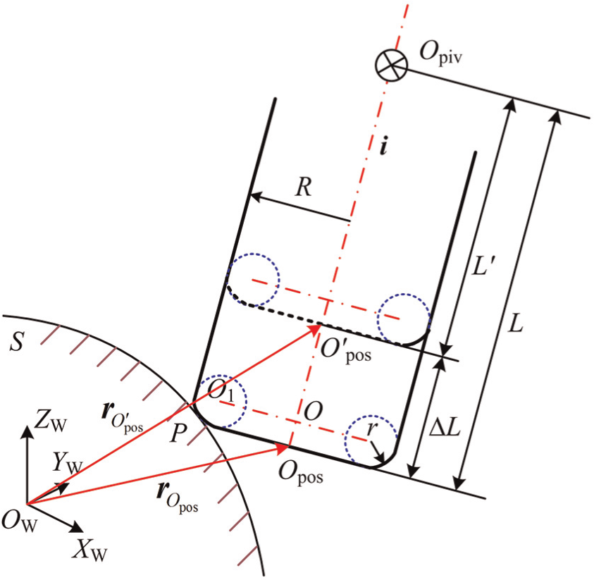
Principle of five-axis tool length compensation.
Method of five-axis tool length compensation
Structure of five-axis machine tool with rotary head and table
Figure 2 is a structural scheme of a typical five-axis machine tool with the rotary head of B-axis and table of A-axis. In the figure, the characters B and A denote the rotary head and table, respectively. The five-axis machine tool adopts the CNC system of SINUMERIC 840D. The travel ranges of tree translational axes are X700 mm, Y400 mm, and Z300 mm, respectively. The travel ranges of two rotational axes are B± 45° and A± 360°, and A-axis is able to rotate continuously.
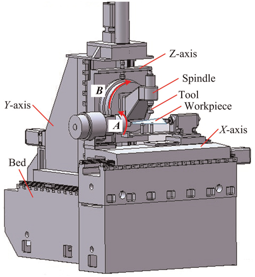
Structure of five-axis machine tool.
Kinematics modeling and solving of five-axis machine tool
The above five-axis machine tool is considered as an example to illustrate kinematics modeling and solving of the machine tool. By analyzing the specific configuration of the machine tool, we can obtain motion relationships between each axis of the machine tool, that is, the kinematics chain of the five-axis machine tool, as shown in Figure 3. The kinematics chain consists of a rotary table, translational table, machine bed, spindle, the cutting tool, and so on.
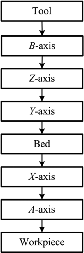
Kinematics chain of five-axis machine tool.
To describe the axis movement of the machine tool, coordinate systems of the five-axis machine tool are created as shown in Figure 4. O
m
X
m
Y
m
Z
m represents the machine coordinate system (MCS), and the machine origin O
m is located at the center of right end plane of A-axis. O
m1
X
m1
Y
m1
Z
m1 represents the coordinate system fixed with B-axis, the origin O
m1 is the intersection point of the spindle center and the center of the B-axis, and each coordinate axis direction of O
m1
X
m1
Y
m1
Z
m1 is parallel to that of O
m
X
m
Y
m
Z
m. O
w
X
w
Y
w
Z
w represents the WCS connected to the workpiece, in which the CL data are given, and each coordinate axis direction of O
w
X
w
Y
w
Z
w is parallel to that of O
m
X
m
Y
m
Z
m. O
t
X
t
Y
t
Z
t represents the coordinate system fixed with the tool, whose origin is located at the point of tool tip or tool center; each coordinate axis direction of O
t
X
t
Y
t
Z
t is parallel to that of O
m
X
m
Y
m
Z
m. In the initial state of the machine tool, it is assumed that the tool axis is parallel to the Z-axis of the MCS, and the origin of O
m1
X
m1
Y
m1
Z
m1 is coincident with that of O
m
X
m
Y
m
Z
m. The position vector of point O
w in the coordinate system O
m
X
m
Y
m
Z
m is (x
0, y
0, z
0)T. In the coordinate system O
t
X
t
Y
t
Z
t, the unit vector of tool position and tool axis is (0, 0, 0)T and (0, 0, 1)T, respectively. Suppose the original pivot length is L, and the actual pivot length is L′,
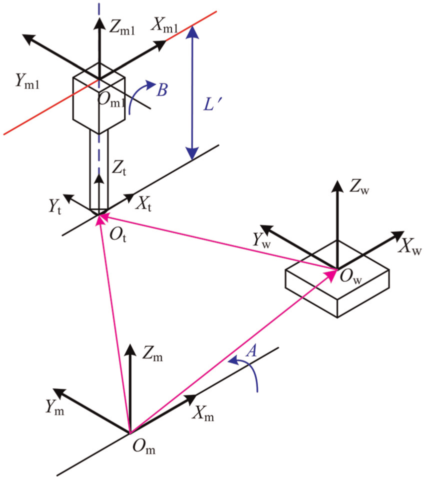
Coordinate systems of five-axis machine tool.
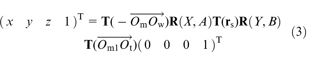
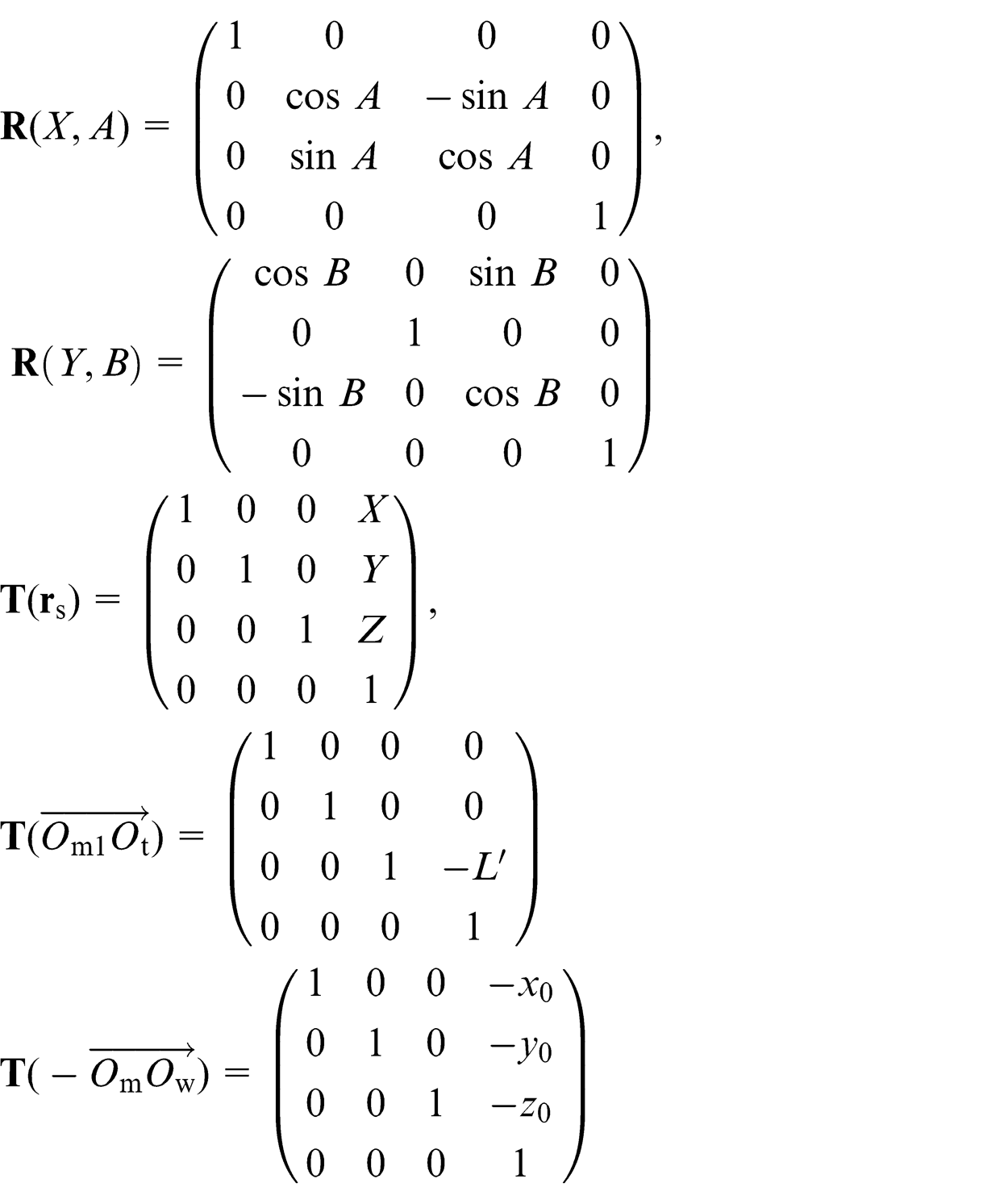
According to the kinematics chain of the machine tool, a set of transformation equations can be derived as follows
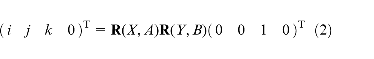
where
Equation (4) can be derived by equation (2) as follows
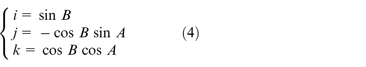
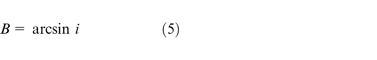
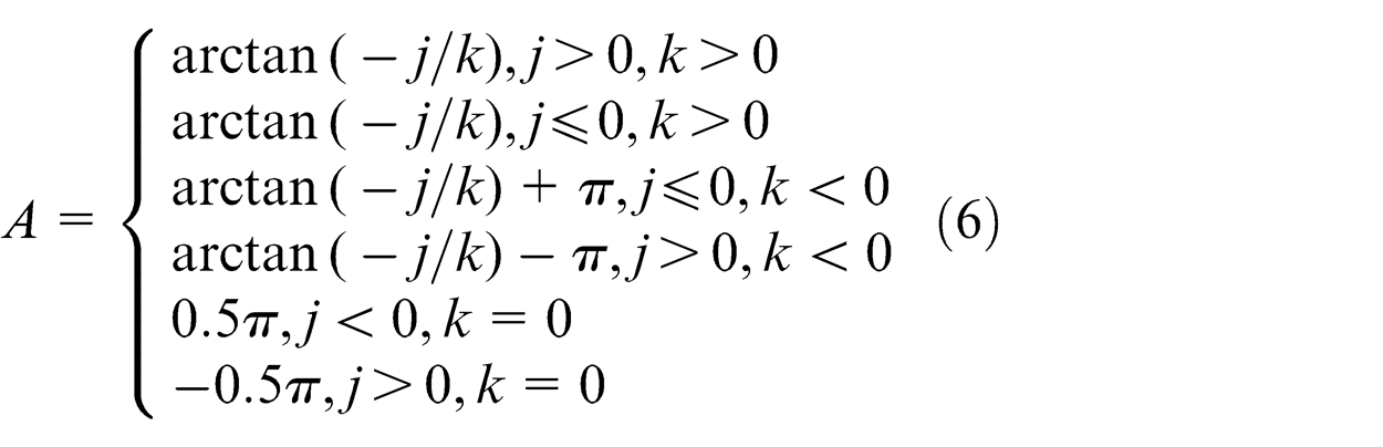
If the rotational ranges of B-axis and A-axis are [−45°, 45°] and [−180°, 180°], respectively, the rotational angles can be solved from equation (4) as follows
With equations (3), (5), and (6), the translational axes of the machine tool can be solved as follows
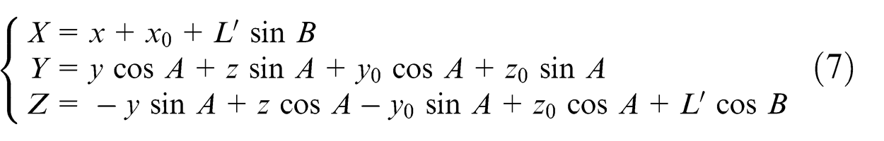
where x 0, y 0, and z 0 denote the initial workpiece origin offset with respect to the MCS, and L′ represents the actual pivot length.
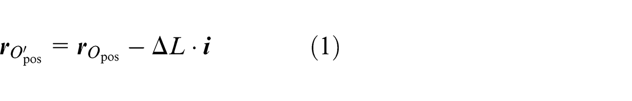
Consequently, the machine coordinates can be determined by equations (5), (6), and (7), that is, the value of each movement axis of the machine tool can be obtained through post-processing the CL file. Up to now, the transformation equation of five-axis machine tool is obtained when the axis direction of the WCS is consistent with that of the MCS. It can be seen from Figure 1 that the change in tool length does not affect the tool orientation, but alters the position vector of tool position. Consequently, the rotary angles of the machine tool (e.g. B and A) remain the same in the NC program, which can be still determined with equations (5) and (6). While the tool length changes, the tool length compensation in five-axis machining can be realized by translating the increment of ΔL along the tool axis vector.
Post-processor development of five-axis machine tool
By using calculation equations of coordinate axes of the five-axis machine tool in the previous section, the actual pivot length value can be set as a macro variable which can be provided by different CNC systems to computer linear axis values in the NC program. Then, a post-processor whose interface is shown in Figure 5 was developed with Visual C 6.0++. The software can not only generate the NC program according to the input value of pivot length in the software interface but also generate the NC program with a macro variable of pivot length. Furthermore, the tool length compensation can be implemented by modifying the value of the macro variable. For example, the macro variable of R parameter is provided by the Siemens CNC system. If R1 represents the pivot length, the NC program with R parameter will be produced by clicking the command of post-process with macro variable in the post-processor software.
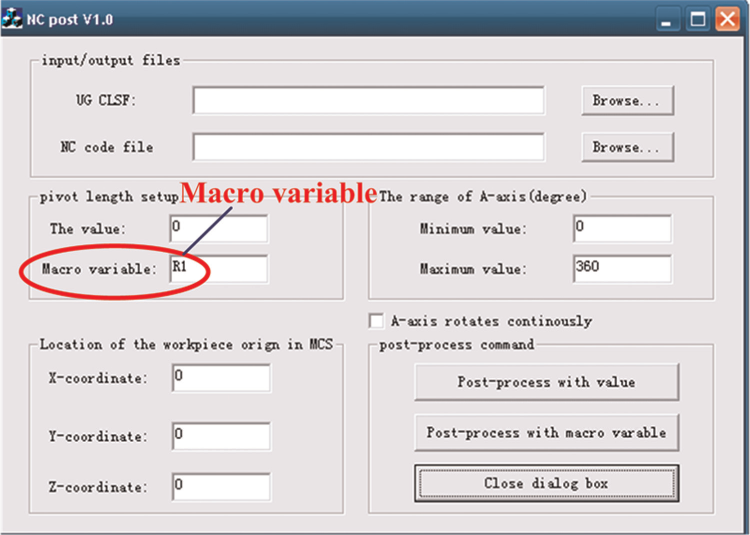
Interface of post-processor software.
Simulation and verification
In order to verify the validity and effectiveness of the proposed compensation method, an aero-engine blade shown in Figure 6 was machined on the five-axis machine tool. The generated NC programs with and without the macro variable of the pivot length were then simulated on the software VERICUT, respectively.
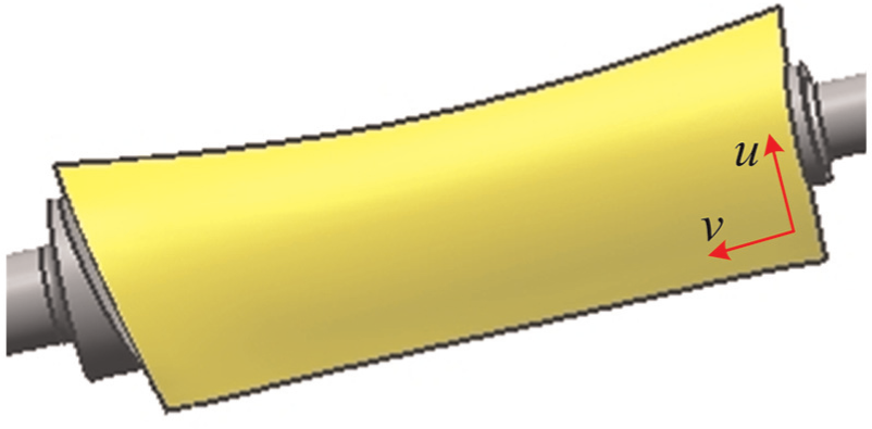
Blade surface.
Assuming the tool moves along u direction, and the machining ranges are v∈[0.1, 0.9] and u∈[0.0, 1.0]; the tolerance of step length is 0.005 mm and the total number of tool paths is 21; tool orientation is determined by “Relative to the drive” of multi-axis machining strategies, the inclination angle is 8°, and the yaw angle is 0°. A torus cutter with the major radius of 10 mm and the minor radius of 1 mm was used to machine the blade surface, and tool paths were generated in the UG/CAM software as shown in Figure 7. Moreover, the corresponding CL file was also obtained, as shown in Figure 8. Then, the NC program with the macro variable was produced by the post-processor developed in this article, as shown in Figure 9.
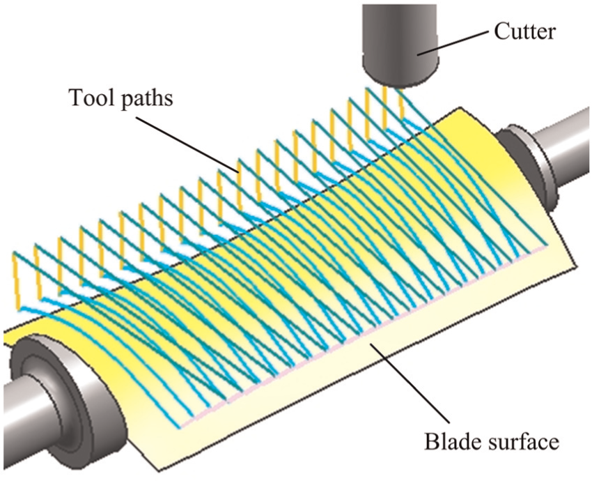
Tool paths generated in the UG/CAM software.
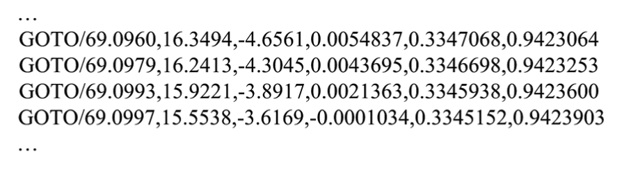
Cutter location file.
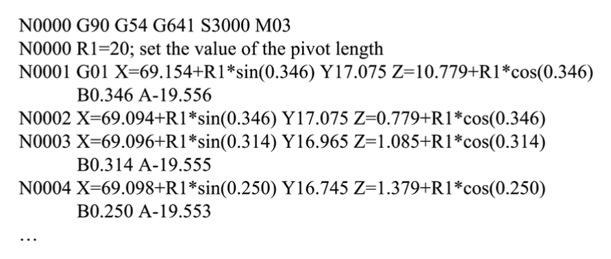
NC program with macro variable.
If R1 was set to be 20 mm in the NC program, and the value of the pivot length L was set to be 20 mm in VERICUT, machining simulation results were as illustrated in Figure 10, in which different colors represent different machining error values. It can be seen from Figure 10 that the maximum excess is about 0.05 mm. If R1 was set to be 20 mm in the NC program, and the value of the pivot length L was set to be 19.9 mm in VERICUT, machining simulation results were as illustrated in Figure 11, where the magenta regions represent the excess value of 0.1 mm. If R1 was set to be 19.9 mm in the NC program, and the value of the pivot length L was set to be 19.9 mm in VERICUT, machining simulation results were as illustrated in Figure 12. It can be seen from Figure 12 that the maximum excess is also about 0.05 mm.
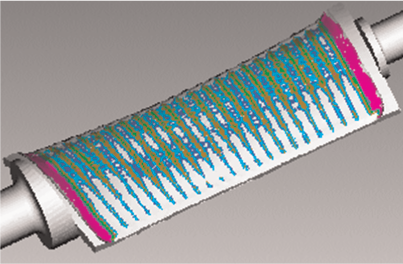
Simulation results with L = 20 mm and R1 = 20 mm.
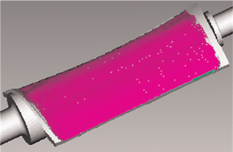
Simulation results with L = 19.9 mm and R1 = 20 mm.
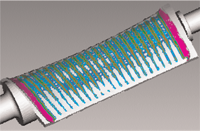
Simulation results with L = 19.9 mm and R1 = 19.9 mm.
As seen from Figures 10 and 11, if the tool length decreases by 0.1 mm, and the original NC program is still utilized, machining errors will increase by 0.1 mm. As can be seen from Figures 11 and 12, if the tool length decreases by 0.1 mm, and the value of the macro variable reduces by 0.1 mm, machining errors in Figure 12 are completely identical to that in Figure 10. Therefore, the tool length compensation function in five-axis machining can be achieved by modifying the macro variable value in the NC program (see Figure 9).
Conclusion
This article proposes a five-axis tool length compensation method using the NC program with macro variable for five-axis machine tools with dual rotary heads or with a rotary head and table. When the tool length changes in five-axis machining, the five-axis tool length compensation can be implemented by modifying the macro variable of pivot length in the NC program. The proposed method neither raises the additional usage cost of machine tools nor increases the work of process planner and the total machining time. Simulated results verify the effectiveness of the proposed method. In addition, the proposed method can be widely applied to early five-axis machine tools without the function of five-axis tool length compensation.
Footnotes
Appendix 1
Declaration of conflicting interests
The authors declare that there is no conflict of interest.
Funding
This work was supported by National Natural Science Foundation of China [grant number 51105026], the specialized Research Fund for the Doctoral Program of Higher Education [grant number 20111102110021], and the Promotive Research fund for Excellent Young and Middle-aged Scientists of Shandong Province [grant number BS2013ZZ002].