
Abstract
Hemiplegia, apoplexia, or traffic accidents often lead to unilateral lower limb movement disorders. Traditional lower limb rehabilitation equipments usually execute walk training based on fixed gait trajectory; however, this type is unsuitable for unilateral lower limb disorders because they still have athletic ability and initiative walking intention on the healthy side. This article describes a wearable lower limb rehabilitation exoskeleton with a walk-assisting platform for safety and anti-gravity support. The exoskeleton detects and tracks the motion of the healthy leg, which is then used as the control input of the dyskinetic leg with half a gate-cycle delay. The patient can undergo walk training on his own intention, including individual walking habit, stride length, and stride frequency, which likely contribute to the training initiative. The series elastic actuator is chosen for the exoskeleton because the torque output can be accurately detected and used to calculate the assisted torque on the dyskinetic leg. This parameter corresponds to the recovery level of a patient’s muscle force. Finally, the walk-assisting experiments reveal that the rehabilitation exoskeleton in this article can provide the necessary assisting torques on the dyskinetic leg, which can be accurately monitored in real time to evaluate a patient’s rehabilitation status.
Introduction
Human walking is the most basic mode of coordinated and voluntary movement with smooth transition, appropriate step length, and stable energy consumption. 1 Exercise therapy based on neurodevelopment facilitation theory is a fundamental rehabilitation method for lower limb movement disorders caused by hemiplegia, apoplexia, or accidental disability resulting from traffic accidents or natural disasters. 2 The application of rehabilitation exoskeletons can free physiotherapists from heavy manual labor and improve training efficiency in terms of the precise motion control and real-time recording of training parameters; this application contributes to the evaluation of rehabilitation. Rehabilitation exoskeletons can be broadly categorized into two types: lower limb wearable style and foot pedal style.
With the exoskeletons of the first type, patients usually undergo training on a treadmill; during training, both legs are tied to the exoskeleton and the upper body is supported by anti-gravity bundling belts. A suspension device is applied to balance the weight of the exoskeleton and part of the patient’s body weight. The exoskeletons of this style generally comprise a walk-assisting platform, an exoskeleton of the upper body, and two legs. Foot parts are usually not considered in these exoskeletons, such as WalkTrainer 3 and Lokomat 4 developed in Switzerland, SUBAR developed at Sogang University, 5 ALEX developed at the University of Delaware, 6 and lower limb walking assistant robot developed at Zhejiang University. 7
For the second type, a pair of multi-variant pedal structures is connected to a patient’s feet for the rehabilitation training. The advantage of this approach is that uneven ground and changing terrains can be simulated to achieve training diversity. The Skywalker by MIT, 8 the 6-degree-of-freedom (DOF) gait rehabilitation robot by Sogang University, 9 and the Haptic Walker by Benjamin Franklin University 10 are significant examples of the second type of exoskeletons.
Traditional lower limb rehabilitation equipments usually execute walk training by driving the legs on the basis of the fixed gait trajectory, which precludes a patient’s initiative. As such, they seem unsuitable for unilateral lower limb disorders because the equipment may interfere between the fixed gait trajectory and the initiative walking intention of the healthy leg.
This article proposes a wearable lower limb exoskeleton for the rehabilitation training of unilateral lower limb disorders. A wearable exoskeleton with a walk-assisting device has been designed to help during walk training. The exoskeleton detects and tracks the healthy leg’s motion in real time; the exoskeleton also provides the necessary assisting torque of the dyskinetic leg. The main design goals of this article are as follows: to improve the training initiative and to dynamically calculate the muscle torques on the dyskinetic leg, and these torques can be used as an evaluation index of rehabilitation training.
Motion analysis of human lower limbs
The motion analysis of lower limbs is of great significance for the walking mechanisms research and the exoskeleton design. It mainly includes the gait characteristics and its influencing factors. The clinical gait analysis (CGA) data are generally used for the human walking analysis and the exoskeleton design. 11 The walking motion is implemented by a multi-dimensional pelvic movement and associated rotations of the hip, knee, and ankle joints. Figure 1 shows the DOFs of the lower limbs. The pelvis plays an important role in maintaining upper balance and increasing the stride length, but its rotation ranges and power consumption are relatively small. 12 So it could be designed as a passive joint. The movements with relatively large rotation ranges are the flexion/extension rotation at the hip, knee, and ankle joints. And the rotation ranges are about 50°, 60°, and 20° in sequence. The other DOFs at the hip and ankle joints are also with micro motions to perform a harmonious and natural walking posture. This will contribute to the vertical upper body and ensure the center of gravity is located between the two feet. As there is a walk-assisting device to keep balanced walking and to support the exoskeleton weight and part of the patient’ body weight, the foot parts tend to be not necessary. Finally, the designing architecture is determined as active driving at hip and knee, and passive rotation joints for the pelvic movement.

DOFs of human legs.
The gait trajectory exhibits individual differences. In general, individual walking habits, different walking speeds, and various body weights are the main influencing factors. In a study, 11 three groups of CGA data have been provided by detecting different groups of subjects. The walking speed is 1.3 m/s and the body weight is 75 kg. The significant differences are shown on the joint angle curves because of the different walking habits of the subjects. In another study, 13 the effects of different loads (0, 10, 20, and 30 kg) and walking speeds (0.8, 1.3, and 1.7 m/s) have been evaluated; the results reveal large joint angle deviations in the joint angle trajectories. The maximum joint angle variations caused by different individual walking habits, speeds, and loads are shown in Table 1.

The large joint angle deviations imply that the fixed gait trajectory is unsuitable for rehabilitation training, especially for patients who suffer from unilateral lower limb disorders but still exhibit an athletic ability and initiative walking intention on the healthy leg. Therefore, intentional walk training can be conducted to drive the dyskinetic leg by real-time detecting and tracking the motions of the healthy leg.
Exoskeleton mechanical design
Several major aspects, such as similar DOF distribution with the human body, human–machine connection method, and walking stability, should be considered in exoskeleton design and system implementation.
Exoskeleton design with the walk-assisting platform
The rehabilitation exoskeleton includes a pelvis segment and two pseudo-anthropomorphic legs. A walk-assisting platform is also required for safety consideration and anti-gravity support. If necessary, a suitable ankle–foot orthosis can be added to the rehabilitation exoskeleton if a patient suffers from some complications, such as foot drop or strephenopodia caused by long-term underactivity.14,15
Pelvic motion is multi-dimensional with small amplitudes. The hip joint exhibits three rotational DOFs as a spherical pair. The knee joint displays a complex skeletal conformation with two DOFs. The knee external/internal rotation is locked when the joint is completely straight and gradually released during the bending process. This rotation DOF could be combined together with the external/internal rotation of the ankle and then not considered. As a result, the knee joint can be designed with one DOF (flexion/extension). Overall, the DOF distribution of the rehabilitation exoskeleton is designed as follows:
Three rotational DOFs at the pelvic and three translational DOFs at the walk-assisting platform;
Three DOFs at the hip (equivalent to a spherical pair);
One DOF at the knee (simplified as a revolute pair).
The overall mobile lower extremity rehabilitation exoskeleton is shown in Figure 2. Four universal casters are placed on the walk-assisting platform, and these casters enable the arbitrary direction of walking. The multi-dimensional pelvic motions are also implemented on the walk-assisting platform. As shown in Figure 3(a), the coronal and sagittal axes are determined by two rotational joints. The vertical axis is realized by the motion of four universal casters on the ground. The up–down motion of the human upper body is achieved by a pair of linear guide rails and sliders.

Mobile lower extremity rehabilitation exoskeleton with a walk-assisting platform.

DOFs design of the mobile lower extremity rehabilitation exoskeleton: (a) DOFs design on the walk-assisting platform and (b) DOFs distribution of the exoskeleton leg.
Pseudo-anthropomorphic powered legs mainly function to detect and track the movements of the healthy leg in real time and subsequently to provide necessary torque assistance for the dyskinetic leg. As shown in Figure 3(b), the hip and knee flexion/extension rotations are power driven; the other DOFs passively move along with the human body.
Man–machine connection modes
The functions of the man–machine connections on the healthy and dyskinetic legs are different. On the healthy side, the connection should detect and track the human joint movements in real time. On the dyskinetic side, the connection should provide the necessary assisted torques for the hip and knee joints. Therefore, connection devices should be respectively designed.
The dyskinetic leg should be driven by the exoskeleton; thus, a rigid binding method is applied to the thigh and shank. For the healthy leg, the hip and knee rotations are detected by the 2-DOF flexible bundling device, as shown in Figure 4. The ranges of the two sliding freedoms are both ±10 mm and maintained at the middle position by balance springs. The stiffness coefficient is very small (2 N/mm) to ensure a relatively low interaction force under the condition of the man–machine position deviation. A thin-film force sensor is placed and preloaded by a pair of balance springs in the lead–lag translational direction. The human movement intentions and the position deviation between the wearer and the exoskeleton are detected by measuring the increase or decrease of the preload force, as shown in Figure 5.
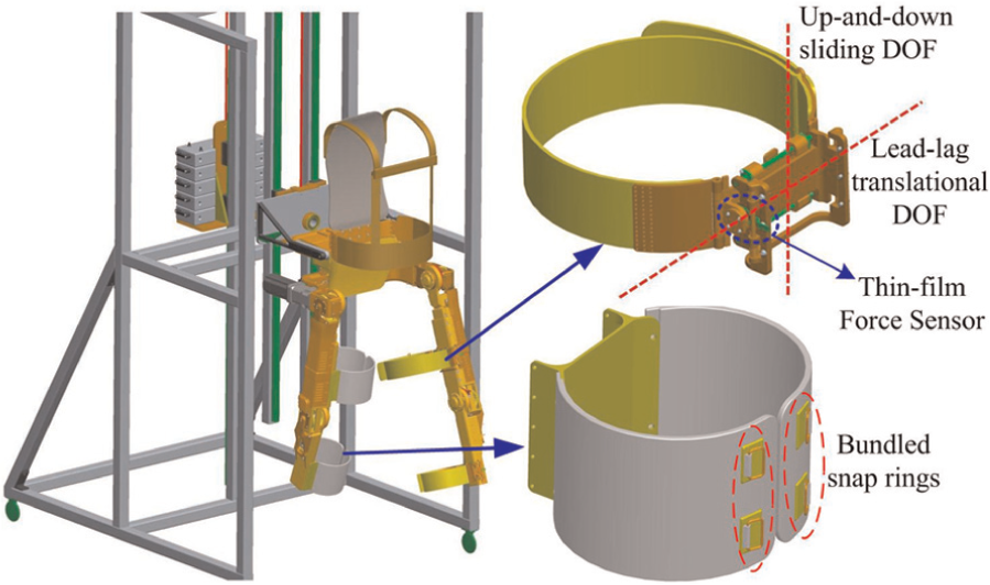
Man–machine connection devices for both the healthy and dyskinetic legs.

Schematic diagram of the 2-DOF flexible bundling device.
Implementation of the walk-training process
For unilateral lower limb movement disorders, the initiative movement of the healthy leg is used to guide the rehabilitation training process. The healthy leg’s motion is detected and used as a control input of the dyskinetic leg with half a gate-cycle delay. The exoskeleton tracks the healthy leg and positions the dyskinetic leg on the basis of the detected joint angle trajectories.
Joint angle detection and follow-up control on the healthy leg
On the healthy side, the exoskeleton tracks the joint motions of the human leg in real time and the control goal is to reduce the man–machine interaction forces caused by

Simplified model of the joint angle detection on the healthy leg.
The hip rotation centers of the human and the exoskeleton are in a superposition state. The exoskeleton joint angles


where
The block diagram of the follow-up control to the healthy leg is shown in Figure 7.
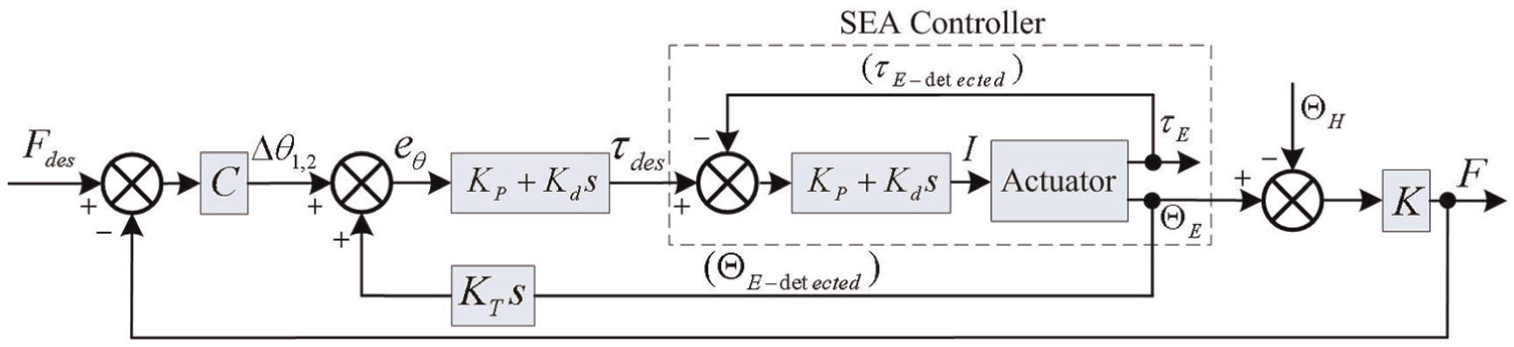
Follow-up control diagram of the healthy leg.
Position control of the dyskinetic leg
On the dyskinetic side, the calculated hip and knee angles of the healthy leg (

Position control diagram of the dyskinetic leg.
Rehabilitation evaluation index
The muscular torque of the dyskinetic leg is the most intuitive evaluation index to evaluate rehabilitation; this value is difficult and inconvenient to detect. A compromise solution is presented by measuring the necessary assisted torques on the dyskinetic leg, and the muscular torque of each patient can be obtained. The SEA is chosen for the exoskeleton joints because the series spring can act as a torque sensor. The structure diagram of the SEA actuator is presented in Figure 9. The torque output can be accurately obtained as follows

where

Joint drive model of the exoskeleton.
On the healthy side, the motor driving torque (

When the dyskinetic leg does not exert any force during walking and its motion is absolutely driven by the exoskeleton, the motor driving torque is
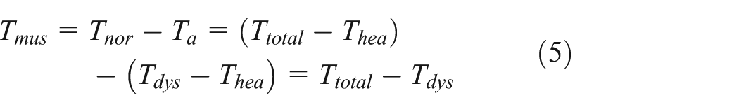
The assistant torque (
Walk-training performance test
Before the test is applied to unilateral lower limb disorder patients, initial walk-assisting experiments should be conducted to evaluate the tracking performance on the healthy leg, the position control performance on the dyskinetic leg, and the walking flexibility.
As shown in Figure 2, the exoskeleton weight is approximately 30 kg. A load of 60 kg is installed on the other side of the walk-assisting platform for gravity balance. The body weight of the subject is approximately 60 kg. So nearly half of the body weight can be supported by the bundling belts on the shoulders and waist to simulate patients with lower limb muscle weakness. Moreover, the gravity balance weight can be increased or decreased to fit different patients. The imitative subject is required to apply minimal exertion on the right leg to simulate the muscle weakness of patients. The walking process is shown in Figure 10, and the experimental steps are listed in Table 2.

Walking process conducted in the laboratory environment.
Description of the experiment steps and the data processing.

The exoskeleton is always in the state of weightlessness. On the healthy side, the exoskeleton joint rotations only need to overcome the influence of the inertia, friction, damping, and so on. So the motor driving torques are small. On the dyskinetic side, the exoskeleton needs to drive the dyskinetic leg during the swing phase and then support the body weight during the supporting phase. As a result, the motor driving torques are relatively large.
The interaction forces on the healthy leg are illustrated in Figure 11. The maximum interaction forces on the thigh and shank are less than 10 N. The maximum angle deviations at the hip and knee are calculated as 1.15° and 0.86°, respectively. The small man–machine interaction forces and angle deviations confirm that the exoskeleton can efficiently track the movement of the healthy leg.
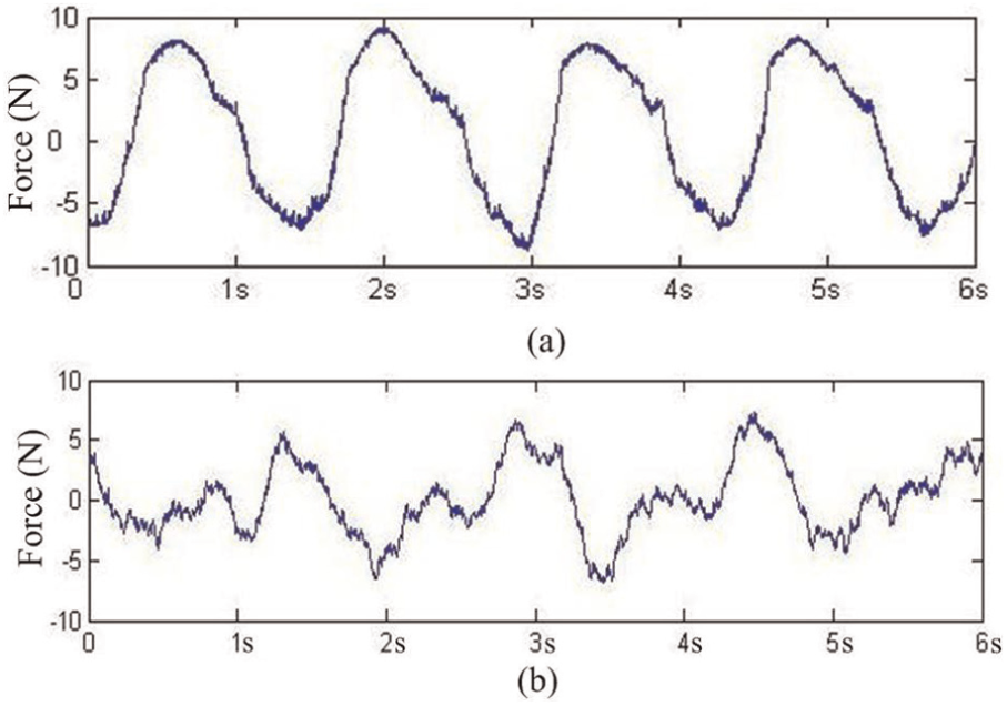
Interaction forces of the healthy leg: (a) the interaction force on the left thigh and (b) the interaction force on the left shank.
For the dyskinetic leg, Figure 12 shows the control input (joint angles of the healthy leg) and the control output (actual angles of the dyskinetic leg). The two curves are almost coincident, and the transitions are smooth.

Control input (joint angles of the healthy leg) and the control output (actual angles of the dyskinetic leg): (a) the hip input and output angles and (b) the knee input and output angles.
The motor driving torques of the three experiment steps were illustrated in Figure 13. The joint torque records during the walk process show that all the muscular torques required for normal walking (
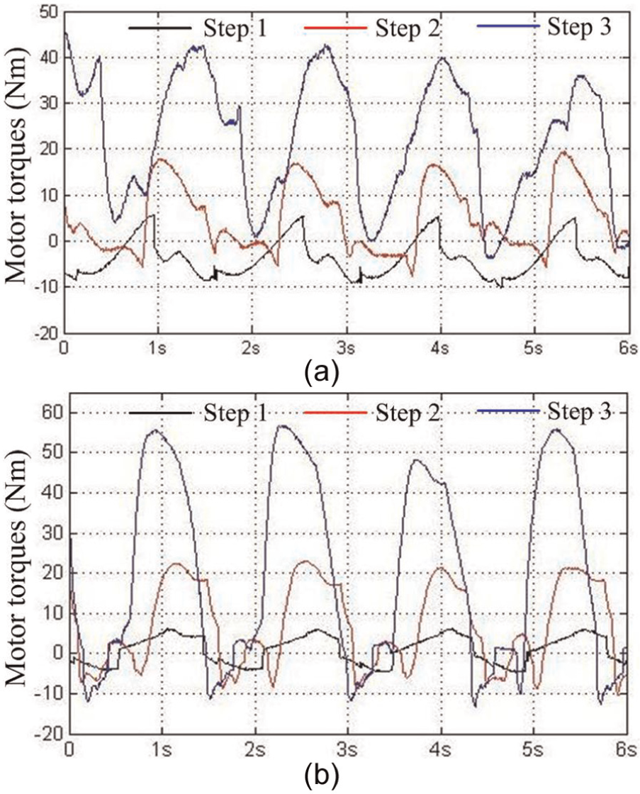
Motor driving torques during the three experimental steps: (a) the motor driving torques at the hip joints and (b) the motor driving torques at the knee joints.
Conclusion and future work
A mobile lower limb rehabilitation exoskeleton is presented for the walk training of patients with unilateral leg movement disorders. The mechanical system comprises a lower limb exoskeleton, a walk-assisting platform, and two different styles of man–machine connection devices. The motion of the healthy leg is detected and tracked by the exoskeleton leg, and the recorded motion data are then used as the control input of the dyskinetic leg with half a gate-cycle delay. Initial walking experiments show that the muscular torque (
Footnotes
Academic Editor: Yong Chen
Declaration of conflicting interests
The author(s) declared no potential conflicts of interest with respect to the research, authorship, and/or publication of this article.
Funding
The author(s) disclosed receipt of the following financial support for the research, authorship, and/or publication of this article: The work reported in this article is funded by “National High Technology Research and Development Program of China (863 Program)” (Grant No. 2012AA041505) and “Self-Planned Task of State Key Laboratory of Robotics and System (HIT)” (Grant No. SKLRS201201A02).