
Abstract
Disabled people require assistance with the motion of their lower limbs to improve rehabilitation. Exoskeletons used for lower limb rehabilitation are highly priced and are not affordable to the lowerincome sector of the population. This paper describes an exoskeleton lower limb system that was designed keeping in mind that the cost must be as low as possible. The forward kinematic system that is used must be a simplified model to decrease computational time, yet allow the exoskeleton to be adjustable according to the patient's leg dimensions.
1. Introduction
The 21st century has seen the realization of wearable robots. From their first introduction into the industrial workplace in the 1960s (Craig, 2005), robots have developed at an incredible rate and now encompass almost every aspect of modern society. Wearable robots are defined as “a mechatronic system that is designed around the shape and function of the human body, with segments and joints corresponding to those of the person it is externally coupled with” (Mohammed and Amirat, 2008). A bio-mechatronic system is needed for such wearable robots, which is the integration of biology, mechanical, electronic and computer engineering, as shown in Figure 1 (Naidu et al., 2012). Due to technological developments, robotic exoskeleton systems have evolved from rudimentary prototypes with limited application to highly sophisticated devices. These systems have the ability to enhance the performance of humans and enable disabled individuals to perform actions according to the Activities of Daily Living (ADL).

Bio-Mechatronics integration concept
There are approximately 250 000 cases of spinal cord injuries per annum in the United States of America alone (Koslowski, 2009). Severe trauma to the spinal cord may result in paraplegia or tetraplegia. Paraplegia is the loss of motor function in the lower extremities, usually with retained upper limb functions. Damage to the central nervous system or spinal cord injuries may result in such a loss of upper or lower limb motor functions (Stokes, 2010). An exoskeleton structure is required for individuals who have lost their motor functions in their lower limbs. Such an injury could result in the implementation of the lower limb exoskeleton.
The concept of using an exoskeleton for protection or enhancement has been around for hundreds of years. However, it was only recently that powered exoskeletons became a reality. One of the first contributions to early development of powered exoskeletons was “HARDIMAN”. This full body exoskeleton was designed by General Electric Co. in the 1960s, comprising an inner and outer exoskeleton which operated on a master/slave control scheme (Pons, 2008). In the last five years there has been major development in exoskeleton systems (Mohammed and Amirat, 2008). Systems such as the Hybrid Assistive Limb (HAL), which is now in the fifth generation, and Berkley's BLEEX, display cutting edge modern technology.
HAL-5 was designed by researchers at the University of Tsukuba, Japan. The HAL-5 was aimed at meeting both strength augmentation and rehabilitation requirements. HAL-5 is a full body exoskeleton which is controlled by two control schemes, namely “Bio-cybernetic control” and “cybernetic robot control” (Sanaki, 2006). The former control scheme utilizes electromyography (EMG) signal detection for augmentation operation. The latter control scheme is used for repetitive activities or when there are no viable EMG signals. This draws on a database of predefined motions for a specific operator (Inc, 2011).
BLEEX is a lower limb robotic exoskeleton which was developed by researchers at the University of California, Berkley, in an effort to improve the load bearing capabilities of the operator. BLEEX is controlled through a highly sensitive control system which uses data from sensors on the exoskeleton to predict the movement of the operator. However, there are no sensors measuring the interaction force between the operator and the exoskeleton (Kazerooni, 2005).
The objectives and contribution of the research were to design, simulate, design and test a lower limb exoskeleton system, which would be the initial construction for future research on advanced robotic prosthetics. This system would be mainly used for rehabilitation of the lower limbs by means of motion within the gait cycle. Future development and research could then be based on this research.
This paper investigates the integration of the biological and mechanical systems within a body, and that of the designed exoskeleton. The objectives and contributions were to develop a forward kinematic model of the system to allow for the motions of walking. The exoskeleton system is required to cost less than US$ 3,000, therefore requiring a system that is reliable, safe and with a simplified control system. Simulations for the gait cycle are shown and tests are performed to show the relationship between actuators and the rehabilitation of a person in motion.
2. Biological and Mechanical Integration
The lower limb of the human skeleton comprises three primary joints, namely the hip, knee and ankle. The Degrees Of Freedom (DOF) each joint permits is illustrated in Figure 2 (Sanaki, 2006).

Lower limb degrees of freedom
The research of the lower limbs initially neglected stability and focused mainly on the motion of the system. The operator's balance could be maintained through the use of stability aids, such as crutches. The aim of the research is to rehabilitate the motion of a person's legs. Hip abduction/adduction and internal rotation do not play a significant role during the walking cycle (Hian Kai et al., 2009), and were omitted from the design. The design developed is seen in Figure 3, which permitted walking in a straight line. This straight line walking means that the hip, knee and ankle joints permit articulation of the limbs in the sagittal plane (Naidu et al., 2011b).

Lower limb design
The ranges of motion for the joints are constrained such that hyper-extension and hyper-flexion do not occur. These ranges are tabulated in Table 1 (Naidu et al., 2011b). Mechanical stops at the extremities act as a failsafe in the event of an electrical or software failure from the safety switches. Lower operational limits can be entered on a graphics user interface (GUI) should a patient need rehabilitation at lower angles.
Joint range of motion

Both the hip and knee DOF were actuated, while the ankle joint was designed to be passive. A torsion spring mounted at the ankle was used to return the foot plate to a neutral position during the swing phase of the walking cycle. Data from clinical gait analysis (Riener et al., 2002) were evaluated to determine the joint torques for the actuated DOF. For a 100 kg system, the torque requirement for hip extension was 80 Nm. The torque required for knee extension during stair climbing was 140 Nm and 50 Nm during walking. Actuators were selected such that the maximum torque was met, which allows for the operator to be raised or lowered from a seated position. Electric linear actuators from Phoenix Mecano's LZ60 range were selected as they offered high speed/load capabilities and a less bulky design than direct mounted rotational actuators.
3. Customizable Kinematic Model
A kinematics analysis was undertaken for the lower limb exoskeletons. The Denavit-Hartenberg (D-H) convention was incorporated for assigning the reference frames. The transformation matrix shown in Equation (1), represents joint i relative to joint i-1. The exoskeletons are rigid serial mechanisms, which allow for the end-effecter to be represented relative to the fixed base frames (Craig, 2005).

Where:
αi–1=distance from zi–1 to zi about xi–1
αi =angle from zi–1 to zi about xi–1
θi =angle from xi–1 to xi about zi
di =distance from xi–1 to xi along zi
The lower limbs have identical kinematic chains, thus the fixed reference frame was defined at the hip, and the transformation matrices relating the ankle to the reference frame were found. These matrices can be seen in Equations (2) – (4), which have been derived from Equation (1) (Naidu et al., 2011b).


The forward kinematics of the exoskeleton leg were obtained using Equation (5) (Craig, 2005). This kinematics model relates the end-effector to the origin of the base frame, which is represented by the GH joint.

3.1 Inverse Kinematic Models (Naidu et al., 2012)
Several inverse kinematic iterative methods exist, of which the Damped Least Squares (DLS) method is superior around singularities and complex designs. The DLS method implements the Jacobian of the positional vector of the mechanism and is required to solve the change in ϑ i (Buss, 2004).
Matrix

The iteration of small angle changes is a function of the Jacobian and results in a linear derivation of the inverse kinematics.
The Jacobian is represented by Equation 7 (Buss, 2004). This will result in an m x n matrix; in this model m = 3 and n = 4.

The change in ϑ i can be determined by Equation 8 (Buss, 2004).

J', λ and I represent the Jacobian transpose, damping factor and identity matrix respectively. The damping factor compensates the computational problems as a result of singularities (Na et al., 2008).
The multiplication of the Jacobian with its transpose produces a square matrix which allows for the computation of the inverse of this multiplication. The error value is the difference between the initial position and the target position. This is updated in the iteration. The algorithm of the DLS method is illustrated in Figure 4. The iteration process is dependent on the error value which is initially calculated. The angle change is then iteratively solved and the error value and joint angles are updated. This process is repeated until the error value is reduced to a desired tolerance.
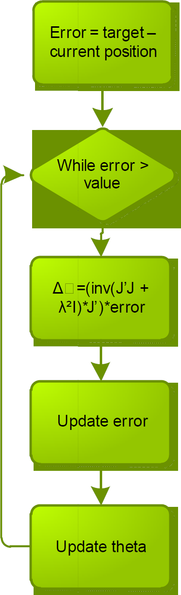
Flowchart illustrating the iteration process of the DLS method
The inverse kinematics were derived analytically and verified through simulations on Matlab®. The workspace, seen in Figure 5, was modelled with the use of Matlab®, which used a random number generation method, and depicts the maximum range of motion for each leg. For simulation purposes, limb lengths were set to L1 = 500 mm and L2 = 430 mm for the thigh and shank respectively.

Range of motion for lower limbs
The plane in Figure 5 represents the sagittal plane, with the anterior of the model facing the positive x direction. The workspace depicts the range of motion of the swing leg (blue), while the stance leg (green) is included for visual reference only. The full scope of the workspace includes the joint ranges both for motion while standing upright and in a seated position.
4. Control Architecture
Instructions such as joint changes or co-ordinate points are performed on a GUI. The data is sent to Matlab® which calculates the relevant kinematic calculations. The calculated or inputted joint angles are then sent to the relevant microcontrollers which will carry out the motor control operations. The Robotic Communication Protocol (Stopforth et al., 2011) was used to send data between the devices. A PD control system was implemented on the system. A GUI interface allows the user to control the exoskeleton system through Matlab®. The kinematic models are calculated and these angles are used as references within the control system. Feedback encoders allow for the positional control model, which is shown in Figure 6. The microcontroller relays the position control back to Matlab®.
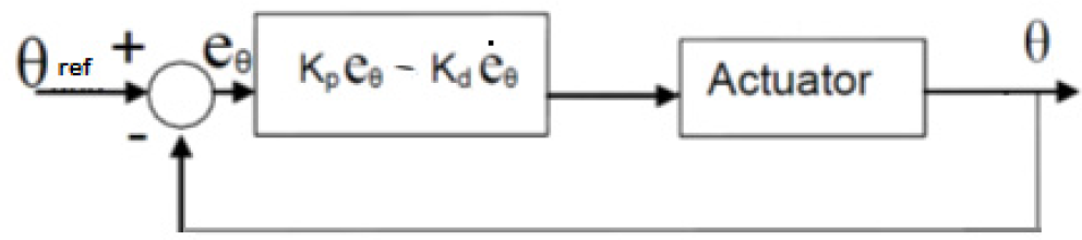
Control architecture of the PD control implemented in the exoskeleton system
The microcontroller that was used for the control of the linear actuators and sensory network is the ATMega 1280 on an Arduino board. Limit switches were placed on the actuators to act as a fail safe system, should the feedback from the encoders on the actuators give inaccurate results. The limit switches acted as homing positions, which reset the counters on the encoders and therefore prevented the person from injuring themselves. The electronic integration of the system is shown in Figure 7.

System integration of the exoskeleton legs
5. Tests and Results
The design of the lower limb exoskeleton was kept simple so as to have a platform to perform tests and observe the interaction of the human-machine interaction. The design of the lower limb exoskeleton that was constructed is shown in Figure 8.
Construction of the lower limb exoskeleton that is being tested for comfort and motion
A stand was developed to mount the exoskeleton legs to, allowing for free motion as if the person were walking on air. This eliminated the problematic area of instability and injuring of any person due to the exoskeleton tipping and falling.
The LZ60P0150 linear actuators from Phoenix Mecano were used in the design of the exoskeleton legs. These actuators operate at 36 V and can exert a force of 2000 N. Tests indicated that there is a linear relationship between the actuator feed-rate and the gait cycle, as shown in Figure 9.

Graph of feed rate (x 10−1 m/s) vs.gait cycle
The graph in Figure 9 shows that the actuator with a feed-rate of approximately 28 mm/s would allow the knee joint to rotate 90° in 1 second. Results shown in Figure 10 indicate the relationship between the actuator length and flexion of the leg.

Graph of actuator length (mm) vs.knee flexion
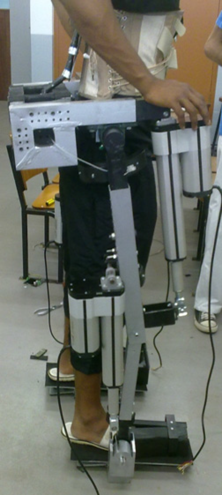
The graph in Figure 10 shows that for a 120° revolution, the actuator moves from 270 mm down to 118 mm, giving the required stroke length of approximately 150 mm. Full motion of the actuators allow for the full gait cycle to be completed, as required for rehabilitation. The final design of the lower limb exoskeleton being tested is shown in Figure 11.

The lower limb exoskeleton being tested
The control system was tested for the weight of 100 kg person. The walking motion was initiated to complete a gait cycle within 3 seconds. The hip flexion and knee extensionjoint angles were monitored for the gait cycles, and the average values were recorded as illustrated in Figure 12 and Figure 13 respectively. Constraint limits of 55° and 60° were placed for the hip and knee joint respectively.

Average hip flexionjoint angle within the gait cycle

Average knee extensionjoint angle within the gait cycle
The maximum power of the actuators for the hip flexion and knee extensions were recorded as being 110 W and 50 W respectively.
6. Conclusion
The lower limb prototype exoskeleton was designed that allowed for hip, knee and ankle joint articulation in the sagittal plane. Other DOF were eliminated on the exoskeleton frame as these motions were used less often for leg rehabilitation. The exoskeleton legs were designed to allow for adjustability and the rehabilitation of a person with a weight less than 100 kg. This weight restriction allowed for a safety factor to be included.
The D-H notation was used to derive the forward kinematics of the mechanism. The D-H parameters were used to derive the relative joint transformation matrices. The workspace of the design was simulated to determine the range of motion. The Damped Least Square method was used to solve the inverse kinematics of the system, allowing determining the angle of each joint.
The feed-rate of the linear actuators was found to be 28 mm/s allowing the knee joint to rotate 90° in 1 second, as required for the gait cycle. For a 120° revolution, a stroke length of 150 mm is required. The results that were obtained for walking motion have shown that the control algorithm and architecture have caused an overshoot for the knee joint of 1° above the constraint limit (60°) indicated on the GUI. An undershoot was observed by the hip joint, which is possibly due to the load on the actuators that damped the chance of an overshoot.
The operation of the biological leg and previous lower limb exoskeletons were researched. The mechanical properties of the biological leg were correlated to the design and development of the exoskeleton legs to allow rehabilitation in the sagittal plane. The objectives explained in the introduction were achieved. The integration of the electronic system to control and operate the mechanical system was explained in the paper. Safety implementation of the system was integrated mechanically, electronically and by means of software. The research has developed a prototype system that allows for the rehabilitation of a person's lower limbs, which came to a total cost of under US$ 3,000. Satisfactory results were obtained to allow future work to be performed on the system.
6.1. Future Work
The actuators that were used in the prototype system had a low torque and speed which could be increased to allow rehabilitation of people with greater weight. Higher torque actuators that have a low weight ratio would be more beneficial, but would increase the cost. The prototype system could be improved and expanded for different types of applications. Adaptive control architecture could be implemented into the GUI model that will take into account the weight of the person. These variables could be determined by sensors placed on the exoskeleton lower limb system.
The designed lower limb exoskeleton system will allow for rehabilitation in an up-right position. Investigation of a lower limb rehabilitation system in a seated position could be considered, with the use of an impedance control system.