
Abstract
Human fingers are essential for many everyday activities, making them vulnerable to a variety of injuries. Finger rehabilitation may be required to restore key functions like range of motion, strength, agility, neurological recovery, and pain relief, especially after events like a stroke. Besides several rehabilitation devices being investigated, there is still a need for a reliable and user-friendly solution. Thus, this paper presents the first steps in the development of an innovative mechanism for rehabilitation of the human finger that allows flexion and extension of individual movements of each phalanx or combined movements for each finger. The proposed device consists of an exoskeleton with an articulated mechanism placed on each finger. The mechanical structure for moving each phalanx consists of a six-bar articulated mechanism with a slider, whose movement is made by a linear actuator. The design process is carefully described, starting from the finger kinesiology, followed by a kinematic modeling of the proposed device, 3D CAD modeling, and the construction of a prototype to index finger, including its control architecture. Both simulations and experimental tests are carried out, showing a suitable behavior of the proposed device in performing both individual and combined flexion/extension exercises of a human finger.
Introduction
Human hands are used for the most diverse daily tasks, and due to this fact, they are subject to different types of injuries. The human body can also be affected by neurological diseases that can compromise hand movements. Therefore, rehabilitation protocols may be necessary to restore/improve finger movements. Procedures for rehabilitation of human fingers involve repetitive movements performed by healthcare professionals who usually lack specific tools to assist in this task. The goal of rehabilitation is to treat or lessen difficulties brought on by neurological aftereffects, chronic illnesses, injuries sustained during pregnancy or childbirth, and workplace and traffic accidents. Rehabilitation can be required to help a person with a handicap rehabilitate physically and psychologically and prepare them for social reintegration, rehabilitation is a global, dynamic process. 1 Furthermore, modern technologies have increased life expectancy, increased the number of elderly people, and made imperative the use of rehabilitation therapy for treating chronic diseases, improving the quality of life, and reducing the impact of disabilities and cardiovascular diseases. 2
The specific field of hand rehabilitation is particularly challenging due to the complex features of the human hand.3–4 The human hand has the function of touching, pressing, holding, releasing, and manipulating objects; performing a variety of motor tasks; and controlling finger movement is essential for these activities. In the event of injuries, coordination of finger movements may be compromised, making daily activities difficult or impossible. After finger movement problems, treatment by hand rehabilitation specialists is required, who administer exercises using external force with passive exercises or by motivating the patient to actively move their fingers to strengthen the muscles. 4 Finger rehabilitation is necessary to help patients regain function in hands and fingers after injuries or surgeries, thus improving the quality of life and regaining control of daily tasks. The finger rehabilitation has the objective of restoring functional range of motion, agility, and strength, adapting to new function in the case of stroke problems, and pain relief with exercises such as proposed in in the work of Kabir et al. 3
Robotic structures can assist in the rehabilitation process by facilitating and promoting natural processes of healing and regeneration and stimulating, optimizing, and compensating for residual capacities. These processing steps frequently require multiple repetitions of finger movements at different amplitudes.5–6 But the complexity of the human hand makes it difficult to develop a suitable device for its rehabilitation. The hand is the distal part of the forearm. This is made up of the carpus, metacarpus, and phalanges. It is formed by the wrist, palm, back of the hand, and fingers. The hand has 27 bones and 17 joints, 7 which makes the task of developing a device that reproduces these movements extremely complex. 8
The current generation of hand rehabilitation devices can be divided into articulated mechanisms (such as exoskeletons) and “wearable” robotic components/soft mechanisms that can facilitate finger mobility. 9
In reference, 10 a finger rehabilitation device was presented based on an exoskeleton architecture for flexion/extension of the finger using cables. The proposed device has five degrees of freedom, each of which is responsible for moving each finger. In reference, 11 an exoskeleton architecture for flexion/extension of one finger was presented as a function of the mechanism synthesis adapted to the patient's finger characteristics with one degree of freedom. In reference, 12 an exoskeleton-based articulated mechanism for finger flexion/flexion all the fingers together with one degree of freedom was presented. In references,13–14 an exoskeleton mechanism with 2-degrees-of-freedom that permits finger flexion/extension movement was presented. In reference, 15 a six-bar mechanism for index finger flexion/extension rehabilitation was proposed. The exoskeleton mechanism with just one degree of freedom is not able to follow the goal trajectory of the fingertip. Other exoskeleton-based articulated mechanisms are presented in references.16–23
In reference, 24 a soft robotic exoskeleton system was presented using a pneumatic flexion element to activate the flexion/extension of the finger. The system was replicated on each finger. A similar idea was implemented in reference 25 with a different geometry of the soft actuators. In reference, 26 a finger exoskeleton design concept using Shape Memory Alloy wires was presented to finger flexion/extension. Other soft mechanism examples are presented in the review papers.4,27–28 The soft robotic devices to finger rehabilitation are promising options in terms of reducing complexity and size and because they have more tolerance for alignment with biological joints. 4 Nonetheless, the soft mechanism can only move all the phalanges together, and the intrinsic nonlinearity needs to be considered in the control system. 25
Most mechanisms present in the literature focus on the combined rehabilitation of phalangeal movements, not allowing the individual movement of each phalanx. In references,29–30 an exoskeleton actuated by cables was proposed with the capacity for combined movement of the phalanges or with the individual movement of the proximal and intermediate phalanges, without individual control of the distal phalanx. In references,31–32 an exoskeleton composed of mechanisms attached to each phalanx, actuated by cables that allow the individual movement of each phalanx or in a combined manner, is proposed. Due to the flexible nature of the cables, the control system ends up being more complex to compensate for errors in the desired trajectories.31–32
Table 1 groups together information on various prototypes developed for human finger rehabilitation, focusing on parameters such as weight and dimensions, capacity to serve a specific finger or several fingers of the human hand, and whether they are capable of individual movements of the finger phalanx rehabilitation. Table 1 also determines the type of mechanism used and the actuators used to move the mechanisms.
Finger rehabilitation devices.

The literature highlights several common issues with the existing finger exoskeleton, such as their inability to adapt to different users. Additionally, they are often bulky, heavy, and difficult to wear. 33 Some of the common problems with finger exoskeletons that have been discussed in the literature can be enumerated here, including the fact that, because they are custom-made for each patient, they are usually not adaptable for different subject fingers, have a large structure and are heavy, or are challenging to wear. 32 New materials, manufacturing processes, sensor developments, and control improvements need to be considered when creating new finger rehabilitation devices to address the above-mentioned known limitations of the existing devices, such as reported in references.3–4,22,34 Furthermore, the design of a hand exoskeleton must overcome several challenges, such as those related to safety, ergonomics, usability, transportability, and wearability.3–4,24–28 Most devices described in the literature permit only simultaneous phalange finger flexion and extension10–12,15–25 (Table 1).
Rehabilitating each phalanx of the finger separately is important 35 for several reasons: each phalanx may have different types of injuries or movement limitations, and specific rehabilitation allows for more targeted and effective treatment for the condition of each phalanx;36–37 each phalanx is moved by different tendons and muscles34,36 and rehabilitating each phalanx separately allows the patient to regain function gradually, which may be less painful; 35 working each phalanx separately can help improve mobility and strength more effectively, 36 since each part of the finger may have different levels of stiffness or weakness; focused rehabilitation can help prevent complications, such as adhesion formation or loss of range of motion, 38 that can occur if all phalanges are treated uniformly; each patient may have different needs, and individualized rehabilitation allows treatment to be tailored to the specific capabilities and limitations of each phalanx. In this way, this paper proposes the design of a novel articulated mechanism using linear actuators that reproduces the primary flexion/extension movements of the finger by enabling both the independent movement of each phalanx or by their combined motion. With an emphasis on finger flexion and extension movements, this structure should enable the implementation of finger rehabilitation/recovery movements, accommodating varying speeds and limits of operation.
This paper proposes the design and prototyping of an easy-to-use, small, and inexpensive (cost below 250 dollars) exoskeleton that also allows for multiple adjustments to adapt to most of the population. In particular, section “Kinesiology of the human finger” outlines the Kinesiology of the human finger, aiming to define the design requirements in terms of the primary dimensions and motion ranges of the human finger. Section “Kinematic models of the human finger and exoskeleton” proposes a kinematic model of the finger and outlines the kinematic model of the proposed exoskeleton. Section “CAD/CAE design model” describes the design of the proposed exoskeleton by presenting its CAD/CAE model. Section “A built prototype” describes a built prototype with its control system. Section “Experimental results” reports the results of experimental tests and suggestions for future work. Section “Conclusions” complete the paper.
Kinesiology of the human finger
The human hand is the part of the upper limb distal to the forearm, composed of the carpus, metacarpus, and phalanges. This is composed of the wrist, palm, back, and fingers, including an opposable thumb. 7 Except for the thumb, which has two phalanges, every finger has three phalanges (proximal, middle, and distal). Every phalanx consists of a body, a distal head, and a proximal base. The orientation of the phalanges is followed by the finger joints. There are two planes of motion possible in the metacarpophalangeal joints: flexion/extension and adduction/abduction (two degrees of freedom). The proximal interphalangeal (PIP), distal interphalangeal (DIP), and metacarpophalangeal (MCP) joints make up the human finger. There is one degree of mobility for flexion and extension in each joint, plus an additional degree of freedom for abduction and adduction movements in the MCP joint (lateral movement of the finger). In this way, these movements are classified into five types: Flexion, Extension, Adduction, Abduction, and Opposition. The most relevant and effective movements of a finger are flexion and extension. Accordingly, we shall consider these key motions for the proposed rehabilitation device.
Flexion is defined by the angular change between the finger phalanges in the direction of hand closure, whereas extension refers to the opposite movement, marked by the angular variation in the direction of hand opening. The angular variations at the joints of a single finger are coplanar in terms of both flexion and extension. 7 According to references,7,39 the ranges of motion for finger joints during flexion are detailed in Table 2, while the driving force for the movement of each index finger joint, based on reference, 23 are shown in Table 3. It should be noted that hyperextension, which is movement beyond the anatomical position, is not included in the values presented in Table 2. The necessary dimensions of the phalanges used in this study were sourced from reference, 40 as detailed in Table 4. The cross-sections of the phalanges are considered ellipsoidal, representing the width (major axis of the elliptical section), by the thickness (minor axis), and the length denoted as l in Table 4. Figure 1 illustrates the key hand dimensions required for the design of the proposed device, based on reference. 41

Hand dimensions (mean ± std [mm]). 41
Range of motion of flexion of the joints of the human hand. 7

Finger force of motion for flexion. 23

Phalanges dimensions of the fingers as based on reference. 40

Kinematic models of the human finger and exoskeleton
The human finger
For the kinematic modeling, a simplification of the human finger was adopted, consisting of three phalanges and three rotational joints, considering only the flexion and extension movements of the fingers (Figure 2). The adopted architecture is like a serial robotic structure. 42 In reference, 8 the mathematical modeling of the index finger is presented as a serial structure with 3 degrees of freedom (Figure 2), and its workspace was obtained. The index finger workspace was used as the expected rehabilitation trajectory for the finger.

Simplified representation of the human finger into a mechanism model.
The proposed exoskeleton
The objective of this paper is to allow the movement of each finger phalanx individually or in combination, and to promote full range of motion of the finger and prevent interference with other fingers, the exoskeleton was designed to be mounted on the back of the hand. To achieve this goal, a six-bar mechanism with a cursor (Figure 3) was selected for the synthesis of its dimensions based on the range of motion and dimensions of the fingers and hands presented in section “Kinesiology of the human finger.” This paper focuses on modeling the mechanism for the index finger.

Proposed mechanism in its initial configuration. Angle between the actuator and the horizontal (ϕ). Angle between phalanges (
From the values of the initial coordinates of A, D, E, and F, together with the values of the lengths L1, L2, L3, L4, and L5, it is possible to calculate the effect of the linear variation of the actuator, P, on the angle formed between the phalanges,

Configuration of the device for calculating the angle
The functioning of the mechanism in Figure 3 is summarized by the expressions:


In a similar way to the calculation with given 


The path synthesis of mechanisms42–44 was used to obtain the device dimensions. Based on the dimensions of the phalanges and the range of motion of each joint (section “Kinesiology of the human finger”), the basic dimensions of the mechanism were established, and the phalanx rehabilitation trajectories were plotted as a function of the dimensional variation of each segment of the mechanism. From the families of trajectories obtained, those dimensions where it was not possible to achieve the expected flexion and/or collision with another phalanx occurred were discarded. By analyzing the trajectories, the dimensions indicated in Table 5 are obtained, considering the dimensions compatible with the hand and with the stroke of commercial compact linear actuators.
Initial values of the proposed mechanism [mm].

CAD/CAE design model
Based on the mathematical model, a Computer Aided Design (CAD) model of the device for the rehabilitation of human hand fingers was developed. Several issues were addressed for a functional design. How will the equipment be attached to the user? How will the users have to position themselves to use the equipment? How will the equipment be able to adjust to different users with different hand/fingers of different sizes?
This paper innovates by allowing each mechanism to move independently, allowing each phalanx to move alone or in combination. Solid Edge software was used to carry out mechanical design and system operation simulations based on the dimensions listed in Table 5 and section “Kinesiology of the human finger.” The device parts are designed to be made of aluminum 1060 and ABS 3D printed (rings finger connections). The linear actuators used have a stroke of 50 mm, a force of 25 N, and a speed of 30 mm/s. It should also be noted that since physiotherapy exercises require time, with sessions generally lasting 30–40 min, 34 the user should be able to remain comfortable for long periods of time. Thus, a base like a chair armrest was created. In Figures 5 and 6, it is possible to see the final device design. The patient's finger is quickly fixed to the device, and the user fits their hand and finger inside the equipment, with the arm resting on the support.

Lateral view of the CAD design of mechanism in Figures 3 and 4. Linear actuators (A). Support to hold the user's forearm (B). Model of a finger (C).

Isometric view of the CAD model of the finger rehabilitation device. Fixing rings (D). Forearm support upholstery (B).
The device was designed to be usable by 98% of the population 45 based on the dimensions provided in section “Kinesiology of the human finger.” To this end, several levels of adjustment have been implemented, as reported in Figures 7 and 8. To deal with different hand/finger sizes and allow the mechanism to be used for different fingers, except the thumb, two adjustments were incorporated. In Figure 7, it is possible to see the slot in which the mechanism is attached, allowing for horizontal adjustment of the layout of the mechanism for rehabilitation of different fingers. For the adjustment of different hands with different depths, two sets of nuts and bolts were used to attach the plate with the slot to the forearm support, allowing for vertical adjustment of the equipment (Figure 7). For a snug fit to different finger depths, adjustable rings were used to secure the device to each phalanx (Figure 8).

Horizontal finger adjustment (blue direction of displacement) and vertical hand depth adjustment (red direction of displacement). Brass nut (A). Slot for horizontal adjustment (B). Spindle for vertical adjustment (C).

Adjustable rings in the proposed device in Figure 6. Rings (A). Finger (B).
Figure 9 shows the prints of the Computer Aided Engineering (CAE) simulation of the distal phalanx motion, and Figure 10 shows the prints of the CAE simulation of the proximal finger flexion. From the CAD/CAE simulations, it is possible to verify the movement of the mechanisms responsible for the movement of the phalanges, depending on the individual or combined activation of the linear actuators.
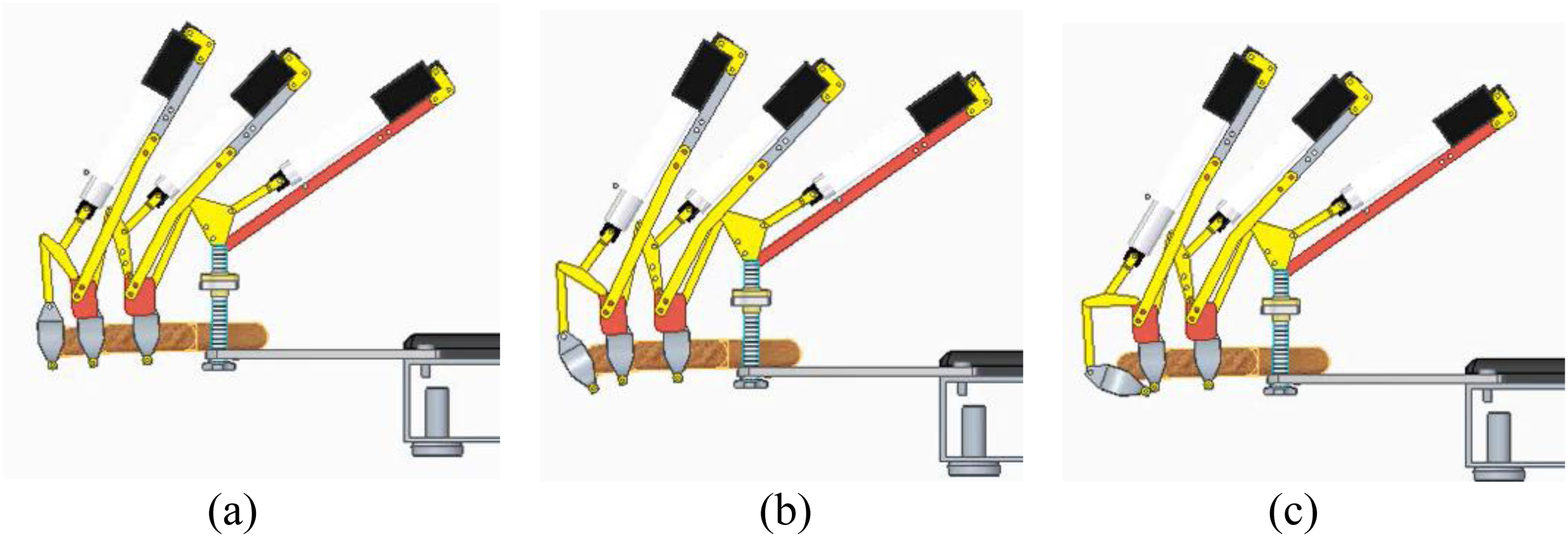
Snapshot of a simulated operation for distal phalanx motion. (a) Initial position; (b) intermediate motion; (c) maximum flexion.

Snapshot of a simulated operation for proximal phalanx motion. (a) Initial position; (b) intermediate motion; (c) maximum flexion.
Except for the adjustable rings on the fingers, all the parts in yellow (Figure 6), referring to the links of the mechanisms coupled to the phalanges, were manufactured in aluminum 1060 with a thickness of 2 mm. The parts were simulated individually using the FEA model in the Solid Edge software. The parts were subjected to a load of 25 N, considering as if all the force of the linear actuator was being applied directly to each part. Figure 11 shows the FEA analysis on two parts with their dimensions in [mm].

Snapshot of finite-element analysis. (a) Link AB; (b) Link EG.
A built prototype
The mechanical components
The prototype structure was manufactured from aluminum parts with different thicknesses of 2-, 3-, 5-, and 10-mm sheets cut by a water jet (dimensional tolerance of 0.2 mm). Parts with more complex geometry were printed in PLA (dimensional tolerance of 0.2 mm). The arm base was made using an aluminum profile covered with a layer of foam. The commercial 25 N linear actuators were purchased according to the required stroke, P, determined based on the maximum finger flexion limits with a stroke of 50 mm and according to the required load according to Table 2.
The passive rotational joints were made with bolted joints, leaving a small gap to allow movement of the segments. We used adjustable rings 3D printed in the device to attach the proposed mechanism at the proximal and distal phalanges. The intermediate phalanx is attached using an aluminum ring to test different designs and comfort to attach the finger. The support to hold the user's forearm uses upholstery.
So that the mass of the mechanism did not overload the phalanx, sizing was carried out to ensure that the center of mass of the system, whether of the set or of each of the mechanisms, was positioned over the hand. For this purpose, the linear actuator was positioned in the anterior part of the joint in such a way that the mechanism that moves the proximal phalanx is fixed to the base structure, the middle phalanx mechanism on the proximal phalanx, and the distal phalanx mechanism on the middle phalanx (Figures 9 and 12). It should also be noted that the mechanism is symmetrical, with the center of mass located in the vertical plane of symmetry of the finger, which coincides with the vertical plane of symmetry of the system. A spindle with an 80 mm length and a brass nut was used to make the depth hand adjustment in function of the values in Figure 1. The prototype is shown in Figure 12.

Built prototype installed on hand mannequin for testing.
The control architecture
An Arduino UNO board connected to two H-bridge L298n modules was used to control the device, as shown in Figure 13. A graphical interface was developed that allows the operator/health professional to easily adjust the device parameters without requiring much time or specific programming knowledge. The used programming language was Python with the Pyfirmata library. The TKinter library for Python was used to create the graphical interface (Figure 14).

Electric circuit assembly scheme of the components.

Device control interface.
This interface features a button that adjusts the device to the extended position, with individual controls for each joint, allowing speed tests to be performed on each joint individually. Additionally, it is possible to create a routine by individually adjusting the actuator force, activation time, and delay for activation. It is also possible to set a pause time between flexion and extension movements based on the rehabilitation protocol to be used. To avoid secondary injuries, the range of movement and speed must be defined by the health professional for each user/patient. The proposed mechanism will have an emergency stop button for an immediate stop if any discomfort occurs to the patient, avoiding the possibility of secondary injuries. Although the mechanism was designed to be usable by 98% of the population 44 based on the dimensions provided in section “Kinesiology of the human finger,” for different index phalanx lengths, the limits of joint movement may be greater or lesser, and it is up to the healthcare professional to set these values in the control system (Figure 14).
Experimental results
To test the constructed prototype and verify the movement values obtained according to the CAD/CAE model (section “CAD/CAE design model”), an anthropometric and anthropomorphic articulated wooden hand was used relative to a person 1.8 m tall (Figure 12). Table 6 presents the comparison between estimated values and obtained values from the CAD/CAE model for the device in the initial position (Figure 15). Table 7 presents a comparison between the estimated values of each parameter and those obtained through the CAD/CAE model for the flexed metacarpophalangeal joint (Figure 16). The estimated values are obtained from a photograph inserted into CAD software to measure the parameters (Figure 17). The photographic method used for comparison is quick, inexpensive, and was employed in the initial stage of developing the proposed device. However, this method is prone to perspective errors, parallax effects, and depth inconsistencies.

Proposed device in the initial position.

Proposed device with the metacarpophalangeal joint flexed.

CAD setup to measure the experimental values of the proposed device.
Comparison between calculated and obtained values for the device in the initial position from Figure 15.

Comparison between calculated and obtained values for the flexed metacarpophalangeal joint from Figure 16.

From Table 6, most values obtained in the prototype show low errors compared to their calculated counterparts, but others exhibit discrepancies. The errors of
We tested two different designs to attach the mechanism to the phalanges: 3D-printed rings and an aluminum ring. Printed rings are more comfortable and adhere better to the shape of the finger. If necessary, padding can be inserted inside the printed parts for better patient comfort. Although the mass of each mechanism is small (about 0.1 kg for each mechanism), it is desirable to add one passive support to alleviate/compensate for the weight of the mechanism on each phalanx.
The videos of the proposed device can be viewed at: https://drive.google.com/drive/folders/1CCPHLM-u-tBWIwCqXKvAaMgJW0rg4M5r?usp = sharing
Conclusions
This paper describes a novel device for human finger rehabilitation. The proposed device allows independent or combined movement of each phalanx with a new mechanism design using linear actuators. The mechanism is designed with features that can adapt it to different patients and fingers. The device is designed with low-density materials to obtain a lightweight mechanism to be coupled to each phalanx (0.1 kg) and it is assembled using available commercial components. Kinematic and 3D CAD models have been implemented. Similarly, a prototype has been built. The results of both simulations and experimental tests show a good match and prove the feasibility of the proposed device for finger movements that need to be validated with tests on patients. Future work will focus on improving the rotational joints, incorporating passive support to reduce the mechanism's weight, and developing a dynamic model to evaluate performance in areas such as response time, accuracy, and control robustness. A thumb movement mechanism will also be considered, along with proper patient trials to assess rehabilitation outcomes in a statistically significant testing campaign.
Supplemental Material
Supplemental Material
Supplemental Material
Supplemental Material
Supplemental Material
Footnotes
Author contribution(s)
Conceptualization: RSG and PEFS; methodology: RSG, PEFS, GMVL, GC, and MC; validation: RSG, PEFS, GMVL, GC, and MC; formal analysis: RSG, PEFS, GMVL, GC, and MC; investigation: RSG, PEFS, and GMVL; writing—original draft preparation: RSG, PEFS, GC, and MC.; writing—review and editing: RSG, PEFS, GMVL, GC, and MC; visualization: RSG, PEFS, GMVL, GC, and MC; supervision: RSG, GC, and MC; funding acquisition: RG and GC. All authors have read and agreed to the published version of the manuscript.
Declaration of conflicting interests
The authors declared no potential conflicts of interest with respect to the research, authorship, and/or publication of this article.
Funding
The authors disclosed receipt of the following financial support for the research, authorship, and/or publication of this article: The authors disclosed receipt of the following financial support for the research, authorship, and/or publication of this article: This work was supported by the Next Generation EU, National Recovery and Resilience Plan, Investment PE8 – Project Age-It: “Ageing Well in an Ageing Society”, PNRR MUR, Conselho Nacional de Desenvolvimento Científico e Tecnológico, Fundação de Amparo à Pesquisa do Estado de Minas Gerais (grant number DM 1557, 11.10.2022 , PE0000013-FAIR, 303511/2021-4, APQ-01885-23).
Data availability statement
Data sharing not applicable to this article as no datasets were generated or analyzed during the current study.
Supplemental material
Supplemental material for this article is available online.
References
Supplementary Material
Please find the following supplemental material available below.
For Open Access articles published under a Creative Commons License, all supplemental material carries the same license as the article it is associated with.
For non-Open Access articles published, all supplemental material carries a non-exclusive license, and permission requests for re-use of supplemental material or any part of supplemental material shall be sent directly to the copyright owner as specified in the copyright notice associated with the article.