
Abstract
To address the problem of workingsteps sequencing in multi-channel turn-milling complex machining, a novel hybrid optimization algorithm titled hybrid discrete differential evolution has been proposed, which improves the algorithm to achieve better results for the workingsteps sequencing problem. The main thrust of this article is twofold: (1) to analyze the characteristics of synchronous machining in multi-channel turn-milling complex machining and their constraints, and to propose a zero-wait micro-resource allocation strategy; (2) to develop a hybrid discrete differential evolution algorithm for process planning in multi-channel turn-milling complex machining, and to describe in detail about the operation of crossover, mutation, and selection. Then, analysis of variance has been used to investigate the contribution and effects of variables (parameters) in hybrid discrete differential evolution, so the optimal parameters can be obtained. Finally, a comparison of the performance and efficiency between the proposed algorithm and the classical differential evolution algorithm is made. And experimental results show that the hybrid discrete differential evolution algorithm is good at solving the sequencing problem, and the results approximate the optimum expectation.
Keywords
Introduction
With the development of computer numerical control (CNC) technology, various configurations of CNC machine tools have been undergoing continuous development. Multi-channel turn-milling complex machining (MTCM) tools as one of the typical advanced machines is getting popular. 1 As shown in Figure 1, in MTCM with multiple spindles and multiple turrets, the whole part can be machined without off-loading using dual spindles, while the machining time can be greatly reduced using multiple turrets. However, in practice, because of the lacking in relative knowledge and experience in MTCM, in some factories, the MTCM is used merely as a turning center. So, the MTCM process planning is attracting more attention.

Multi-channel turn-milling complex machining tool.
The ability to deal with synchronous machining workingsteps is a unique characteristic of MTCM process. There are two steps to follow in order to get an effective MTCM process plan. Primarily, the choice of synchronous machining method has to be made. Then, the synchronous workingsteps have to be sequenced.
There are two kinds of synchronous machining types in MTCM (as shown in Table 1); these two types differ in the number of workpieces to be machined, with one type machining two workpieces while the other machining a single part. The sequencing mechanism of the two machining types is different; the objective of the synchronous machining of the workpieces is the minimization of the difference between the time spent on the two turrets machining the two workpieces. While the objective of the synchronous machining of a single workpiece lies mostly in the minimization of the time difference between each synchronous workingstep. Although the application of MTCM has only a short history, workingsteps sequencing in MTCM is gaining more and more attention, and there are some related researches and literature. Currently, the literature in this field mainly focuses on synchronous machining of two workpieces, 2 while few literature could be found about the synchronous machining of a single workpiece. This article focuses on the latter.
Two kinds of synchronous machining types in MTCM.


MTCM: multi-channel turn-milling complex machining.
Recently, alternative to conventional techniques, evolutionary optimization techniques have been widely used to solve the sequencing problem of process planning.3–5 Some of the research works, process sequencing based on genetic algorithm 6 and differential evolution (DE) algorithm 7 were considered, which, however, are relatively poor at finding the precisely optimum solution and may have premature convergence toward a local minimum. To compensate for the shortage of the individual algorithms and to obtain a more robust optimization technique, it is a common practice to combine different optimization techniques as a hybrid approach. The hybrid approaches have attracted most of the research attention.8–10
However, for workingsteps sequencing with MTCM, only a few works have been carried out. N-C Chiu et al. 1 proposed a genetic algorithm for scheduling a machining sequence, but the turning and drilling were not considered as a synchronous machining process. D-H Chung and SH Suh 2 considered minimizing the cycle time for complex machining, and listed all the possible solutions by enumeration, but this method applies only on parts with only a few workingsteps, otherwise the amount of computation will be greatly increased. As shown in M Tasgetiren et al.’s 11 research work, the DE algorithm plays an important role in the treatment of sequencing and scheduling problem.12–14 There are some researches focusing on process planning, but their performances are not so satisfactory.
Based on the above research works, this article proposes a hybrid discrete differential evolution (HDDE) algorithm by considering the minimization cycle time in MTCM. Then, orthogonal array and analysis of variance have been used to investigate the contribution and effects of variables (parameters) in HDDE, so the optimal parameters can be obtained. Here assuming that the MTCM has two spindles and two turrets.
The aim of this article is to settle the workingsteps sequencing problem in MTCM. This article is structured as follows. Section “Introduction” introduces the feature of workingsteps sequencing problem in MTCM and the methods adopted in similar solutions. Section “Classification and selection method of synchronous machining” presents the classification of synchronous machining and selection of the properties of synchronous machining workingsteps. Section “Workingsteps sequencing with HDDE algorithm” discusses the sequencing of the workingsteps based on the HDDE algorithm in detail. Then, the proposed algorithm will be verified by an instance in section “Illustrative example.” Section “Conclusion” concludes the article.
Classification and selection method of synchronous machining
Classification of synchronous machining
The typical characteristic of a process in MTCM is the ability to conduct synchronous machining, which reduces the machining time and at the same time enhances machining precision. In this article, synchronous machining is divided into three types: (1) synchronous machining of a single feature (SMSF), (2) synchronous machining of two same features (SMTSF), and (3) synchronous machining of two different features (SMTDF). How to select the synchronous machining workingsteps and to ensure that there will be no disturbance between the workingsteps may affect the quality of a MTCM process directly. By studying the types of synchronous machining and analyzing the characteristics of synchronous machining workingsteps, the feasible synchronous machining methods can be concluded, which can be divided into six kinds of combinations as shown in Table 2.
Feasible synchronous machining methods.
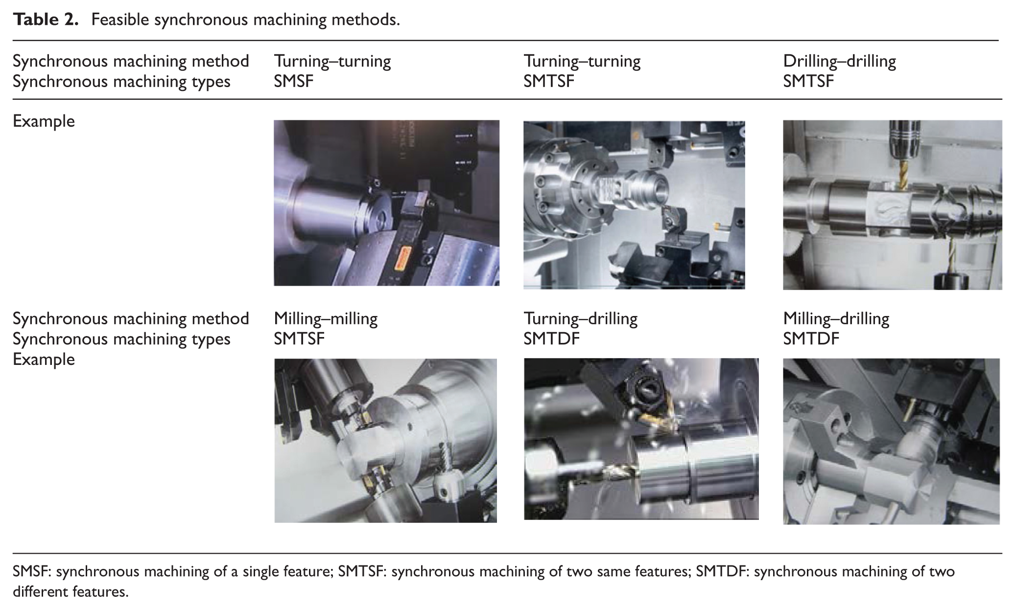
SMSF: synchronous machining of a single feature; SMTSF: synchronous machining of two same features; SMTDF: synchronous machining of two different features.
Constraints of synchronous machining
There are various constraints between workingsteps in MTCM, which can be divided into two main categories: precedence relation constraints and resource constraints.
Precedence relation constraints
Precedence relation constraints refer to the precedence relations between worksteps based on process knowledge and the topological structure of part features. Digraph can be used to describe the precedence relations between workingsteps, as shown in Figure 2. In Figure 2, the arrow indicates the precedence between two related workingsteps. The workingstep at the start of the arrow takes precedence over the one at the end, for example, Workingstep 1 takes precedence over Workingstep 3. In order to accurately describe the relationship between workingsteps in the figure, this article introduces the logical relationship such as “OR” and “AND,” where the dotted line indicates the logical relationship “OR” and the solid line indicates “AND.” For example, Workingstep 5 is preceded by Workingstep 1 or Workingstep 2, while Workingstep 8 can be carried out only when Workingsteps 3 and 4 are finished.

Digraph of workingsteps.
Resource constraints
Resource constraints refer to the influence of spindle and turret. The state of spindle and turret is an important reference factor for the choice of synchronous machining method. There are some rules to follow when using the spindle and turret: only one workpiece can be installed on a spindle at a time, and one turret can only process one workingstep at a time, while the two turrets can process different workingsteps synchronously.
Synchronous workingsteps selection method
The aim of synchronous workingsteps selection is to get the minimized cycle time, which means the two turrets should be assigned to the machine as quickly as possible, and their machining time should be close enough. Otherwise, the processing cycle time will be increased, thus decreasing the productivity. Processing methods in MTCM include both synchronous machining methods and traditional machining methods. Table 3 makes an overall comparison of all the processing methods. (1) The SMSF processing method enjoys the highest priority, in which the machining time between the two turrets is the closest. This method is often used in cylindrical turning. (2) The SMTSF processing method has medium priority, in which the machining time of the two turrets is the same. This method is often used in machining of two symmetrical features. (3) The SMTDF processing method has relatively higher priority over SMTSF; it can be a combination of turning, milling, or drilling theoretically. It should be ensured that there are no precedence relations between the two selected workingsteps. (4) The conventional processing method has the lowest priority, which can be used on any workingstep.
Contrast of the MTCM processing methods.

SMSF: synchronous machining of a single feature; SMTSF: synchronous machining of two same features; SMTDF: synchronous machining of two different features.
According to the precedence relation and resource requirements of MTCM processing methods, this article proposes a synchronous machining workingsteps selection method, and the flowchart of which is shown in Figure 3. First of all, we can get the alternative workingsteps based on the digraph of workingsteps, and store them in a set O, which is marked by

Flowchart of the synchronous machining workingsteps selection method.
If both turrets are idle, there are three possible scenarios: (1) judge whether the selected workingstep meets the condition of SMSF processing method, if it does then this step is signed by
If only one turret is idle, suppose the machining workingstep is
Workingsteps sequencing with HDDE algorithm
DE has received much attention concerning its potential as a new optimization technique for complex non-linear problems and has been successfully used in various areas,15–17 but its local search ability is not good and may have premature convergence toward a local minimum. 18 And the key problem is that the traditional DE cannot guarantee the feasibility of the workingsteps sequencing in MTCM. In essence, workingsteps sequencing problem in MTCM is a complex combinatorial optimization problem which integrates sequencing and scheduling. By inspiration from Li and Mcmahon 19 and Li 20 where some evolutionary algorithms were designed for scheduling problems, a new HDDE algorithm will be proposed. In this section, the traditional DE algorithm will be introduced, and then the mathematical formulation for workingsteps sequencing.
DE algorithm
Since R Storn and K Price 21 proposed the first DE variant, DE algorithm is becoming one of the most used population-based stochastic metaheuristics. Its popularity is mainly due to its simplicity and effectiveness in solving various types of problems, including multi-objective, multi-modal, dynamic, and constrained optimization problems.
In DE, the ith individual at generation t is denoted as
The ith mutant individual is represented by

where
The crossover operator is applied to generate a trail vector
where
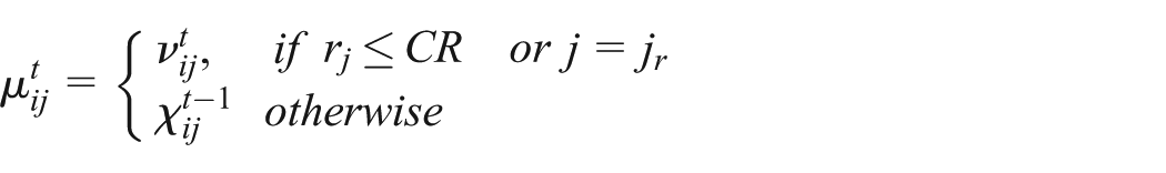
For a minimization problem, the selection scheme is used to compare the trial individual

where
HDDE algorithm
This article proposes an HDDE algorithm for the workingsteps sequencing in MTCM. The individuals in the algorithm refer to the processing programs and the elements in each individual refer to the workingsteps in the corresponding program. The flowchart of the HDDE is shown in Figure 4. In this algorithm, there are a few steps as follows:
Create initial processing NP solutions randomly based on workingstep digraph.
Generate the next generation of sub-processing programs by improved mutation and crossover operations.
During the selection phase, create MTCM process planning methods through zero-wait micro-resource allocation strategies first, and then calculate the objective function of all programs. Combine the transfer mechanism of simulated annealing (SA) with greedy selection mechanisms of DE algorithm to determine whether the termination condition is satisfied, if not, select the new program into the next cycle, otherwise select the best solution as the final program. In the following, the improved mutation and crossover operations and the selection operation will be introduced in detail.

Flowchart of HDDE operations.
Improved mutation operator
It can be known from the mechanism of DE that the mutation operation represents the behavior of information exchange and mutual learning of individuals in the optimization process. The traditional method cannot guarantee precedence constraints; 23 in order to ensure the precedence constraint relations between the workingsteps, this article proposes a new method by the following steps, which can inherit the relations from parent individuals. In this method, each individual denotes a series of sequenced workingsteps, which is called a program in the following.
Step 1. Randomly select three programs from initial population, which are marked by P1, P2, and P3.
Step 2. Randomly select one workingstep from initial P1, which is marked by R1. Find all of its precedent operations from the workingstep digraph, and store them in a set R.
Step 3. Find the workingsteps’ positions in set R from the program P1, which are marked by
Step 4. Calculate the new positions in R for offspring programs, which can be marked by

where Fr is the mutation factor that ranges from 0 to 1. Store all the
Step 5. If
Step 6. Fill the other workingsteps in program P3 in the blanks of the new program in sequence.
Set Fr as 0.6, the proposed mutation operation on the nine-workingstep example-1 is shown in Table 4.
Mutation operation on the nine-workingstep example-1.
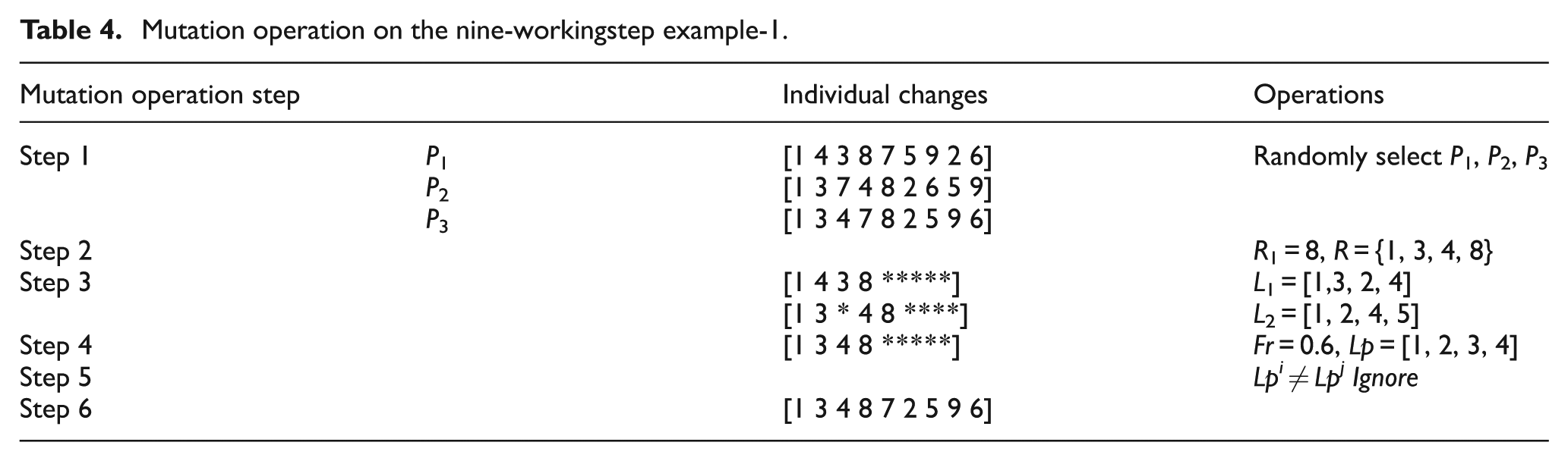
Table 3 shows how the mutation operation works. In Step 1, three programs from the initial population are randomly chosen and marked by P1 = {1 4 3 8 7 5 9 2 6}, P2 = {1 3 7 4 8 2 6 5 9}, and P3 = {1 3 4 7 8 2 5 9 6}. In Step 2, the Workingstep 8 is randomly chosen and then traced back to all its precedent workingsteps, and all the workingsteps are stored in a set R = {1, 3, 4, 8}. In Step 3, the position of Workingsteps 1, 3, 4, 8 in programs P1 and P2 is found, then stored in L1 = {1, 3, 2, 4} and L2 = {1, 2, 4, 5}, respectively, while at the same time, the precedence relations are inherited. In Step 4, calculate the position Lp for new program by importing Lp1 and Lp2 into equation (1). Assume Fr = 0.6, then Lp = {1, 2, 3, 4}. In Step 5, fill in the remaining workingsteps {2, 5, 6, 7, 9} following their orders in P3. The mutation operation is now completed with a new program [1 3 4 8 7 2 5 9 6] which not only inherits the relative orderings from both parents but also satisfies the precedence constraints.
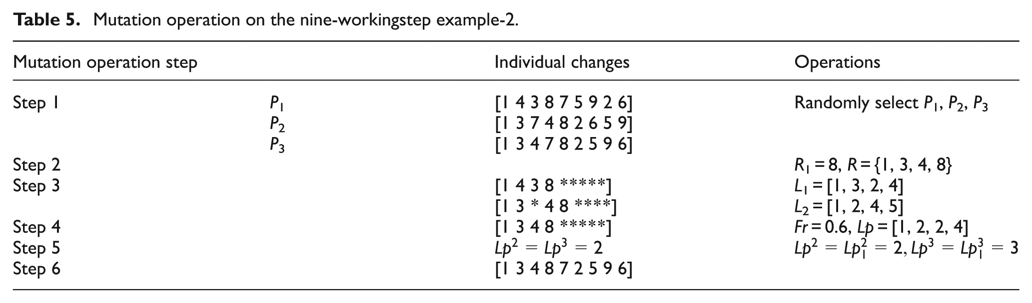
But another situation may occur that when L1 = {1, 3, 2, 4} and L2 = {1, 2, 3, 5}, assuming Fr = 0.6, then Lp = {1, 2, 2, 4}, which is an infeasible solution. In order to avoid this situation, we rule that if
Mutation operation on the nine-workingstep example-2.
Improved crossover operator
In order to increase the diversity of the perturbed parameter vectors, crossover is introduced. 24 The crossover operator generates a trial individual by combining a mutant individual and a target individual, and we expect the individual to be better than target individual. With the increase in crossover factor Cr, more changes are introduced into the new generation. The traditional method cannot guarantee precedence constraints; 25 this article proposes a new program to well inherit good structures from the target individual and to yield a better mutant individual, an improved crossover operator is given as follows(illustrated by an example in Table 6):
Step 1. Select the mutant individual, which is marked by P1.
Step 2. Randomly generate the probability for each element in the selected program, denoted as Q.
Step 3. Set Cr, where Cr is the crossover factor that ranges from 0 to 1. If Q ≥ Cr, the element does not change. If Q < Cr, based on the experience of the search mechanism in tabu search algorithm, judge the exchange workingsteps by neighborhood search mechanism
Step 4. If all the elements in P1 have been traversed, output the new program. If not, return to Step 3.
Crossover operation on the nine-workingstep example.

Set Cr as 0.5, the proposed crossover operation is shown in Table 6.
Table 4 shows how the crossover operation works. In Step 1, one program from the initial population is randomly chosen which is marked by P1 = {1 4 3 8 7 5 9 2 6}. In Step 2, randomly generate the probability for each node in P1, such as Q = {0.6, 0.2, 0.5, 0.6, 0.7, 0.3, 0.6, 0.8, 0.5}. In Step 3, suppose Cr = 0.5, compare each element of Q with Cr and obtain the elements Q(i) satisfying Q(i) < Cr. In this example, the Workingsteps 4 and 5 are likely to be exchanged. Workingstep 4 has the immediate previous Workingstep 1 and next Workingstep 8, then they can be stored in set N1 = {1, 4, 8}. Workingstep 5 has the immediate previous Workingsteps 1 and 2 and next Workingstep 9, then they can be stored in set N2 = {1, 2, 5, 9}. According to the neighborhood search mechanism in P1, there is no relationship between Workingsteps 4 and 3, or between Workingsteps 7 and 5, then the two pairs of neighborhood workingsteps should be exchanged. The crossover operation is now completed with a new program [1 3 4 8 5 7 9 2 6]. Applying the proposed crossover in the parent program results in a new program which is different from its parent. This increases the chance to explore the search space and guarantees to keep the feasible ordering.
Selection operator with zero-wait micro-resource allocation strategies
The purpose of selection is to transfer the optimized individuals to offspring. The performance index taken in this research is the cycle time in MTCM, which can be approximated in equation (2)

where
After calculating the fitness of each individuals, the best and worst individuals are obtained, as well as the individuals generated in the mutation and crossover operations along with their values. In order to increase the diversity of the target population, the transfer mechanism of the SA algorithm is used to prevent individuals from dropping into local traps. 26 The selection method is in the following steps:
Step 1. Calculate the cycle time for target individuals, mutation individuals and crossover individuals based on the zero-wait micro-resource allocation strategy.
Step 2. If the value of mutation individuals or crossover individuals is smaller than the worst of the target individuals, the smallest value is selected. (In this article, we assume that a smaller value yields a better result.)
Step 3. If the values of crossover individuals and mutation individuals are larger than the worst of the target individuals, then accept these individuals by probability P, where P is the selection factor.
Step 4. If the termination condition is satisfied, output the best value and the best solution.
Illustrative example
Analysis of the machining part
As explained in the above sections, here, we will demonstrate how to solve the workingstep sequencing problem in MTCM by HDDE algorithm. The part is shown in Figure 5; it has 22 features and is supposed to be machined in 30 workingsteps. The workingsteps for the part are implemented in a process planning decision system called PPDS, which is a prototype developed by our research team (for details, see Liu 27 ). According to process characteristics of MTCM and the topological relationship of the part, a digraph can be established, as is shown in Figure 6, where the workingsteps in the same dotted box will be clamped at one spindle. Therefore, the Workingstep 11 can be set up at any spindles. The feature information, corresponding workingsteps, available spindle, turret information, and so on are shown in Table 7, where S1 represents spindle1; S2 represents spindle2; Tur1 and Tur2 denote turret1 and turret2, respectively; and T1, T2, …, T12 represent the number of the tools installed on the turret. The machining time is derived from the Computer Aided Manufacturing (CAM) simulation software, with the assumption that no collision happens in the machining.

Part for test.

Digraph of workingsteps.
Feature and the corresponding workingstep information.

Performance of the proposed HDDE
In this section, the proposed HDDE algorithm is applied to solve the workingsteps sequencing problem in MTCM. In order to analyze the influence of parameters Fr, Cr, and NP on HDDE, we have conducted several independent tests by setting the range of Fr and Cr as 0.1 to 1 with a step of 0.1 and considering the value of NP as 45 and 60, respectively. The relation of Fr and Cr with number of iterations before convergence can be seen in Tables 8 and 9. The proposed HDDE algorithm and data model are compiled in Visual C++, while tests and validation are carried out using a PC with 2.33 GHz Intel Xeon CPU and Windows XP.
Relation of Fr and Cr with number of iterations before convergence (NP = 45).

Relation of Fr and Cr with number of iterations before convergence (NP = 60).

To clearly illustrate the relationship of Fr, Cr, and NP with GEN, relation curves are provided as shown in Figure 7. The solid curves in the figure show the changes of GEN under different values of Cr when NP equals 45, while the dotted curves show the changes when NP equals 60. It can be seen from the figure that, generally, the values of GEN are higher on the two ends while lower in the middle, which means that, as Fr increases, the value of GEN decreases at first but gradually increases at last. Multiple curves reach their minimum when Fr equals 0.5. So, it can be concluded that when Fr equals 0.5, the value of GEN is relatively low and the iteration number is relatively high.

Relation of Fr–GEN.
Through further analysis of the data in Figure 7, the average value and mean square error of GEN under different values of Fr are shown as the curves in Figure 8, in which AVG represents the curve of the average value and MSE represents the curve of mean square error. It can be seen from the figure that when Fr equals 0.5, the average value of GEN reaches its minimum, which indicates the highest iteration number.
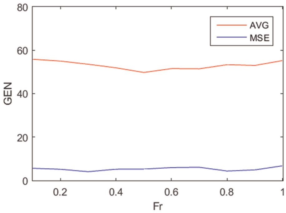
AVG and MSE of Fr–GEN.
The relation between Cr and GEN is established based on the above data, as shown in Figure 9. The solid curves in the figure show the changes in GEN under different values of Fr when NP equals 45, while the dotted curves show the changes when NP equals 60. It can be seen from the figure that, generally, the values of GEN are higher on the two ends while lower in the middle, which means that, as Cr increases, the value of GEN decreases at first but gradually increases at last. Multiple curves reach their minimum when Cr equals 0.7. So, it can be concluded that when Fr equals 0.7, the value of GEN is relatively low and the iteration number is relatively high.

Relation of Cr–GEN.
Through further analysis of the data in Figure 9, the average value and mean square error of GEN under different values of Fr are shown as the curves in Figure 10, in which AVG represents the curve of the average value and MSE represents the curve of mean square error. It can be seen from the figure that when Cr equals 0.7, the average value of GEN reaches its minimum, which indicates the highest iteration number.

AVG and MSV of Cr–GEN.
Furthermore, in order to compare the performance and efficiency of our algorithm with analogous methods, the classical DE algorithm has been used for process planning of MTCM. When applying HDDE in this use case, if the minimum value of the objective function remains the same after 15 times of iterations, then the algorithm can be seen as converged. Figure 11 shows the result of the best cycle times with iteration by taking Fr=0.5, Cr=0.7 and NP=45 in DE, and Fr=0.5, Cr=0.7, NP=45, P=0.4 in HDDE. It can be seen that HDDE always gets the best results than other algorithms, and the best value is achieved by running 55 times, while DE gets the best value with 65 times approximately, and the value is relatively larger.

Comparison of the HDDE algorithm with DE.
Based on the above comparisons, it can be concluded that the HDDE is superior to the other algorithm in terms of solution quality, robustness, and iteration times for the workingsteps scheduling problems in MTCM. This could be explained by the fact that in the HDDE algorithm, better initial values are generated for the local search algorithm by performing global exploration, while the local search algorithm further refines the obtained solutions by performing local exploitation. That is to say, the superiority in terms of searching quality and robustness of the HDDE algorithm should be attributed to the combination of global search and local search, that is, the balance of exploration and exploitation.
The best solution of MTCM is shown in Figure 12, where Workingstep 27 and Workingstep 10 are processed at the same time. The linear combination of Workingstep 2 and Workingstep 5 with Workingstep 29 is processed with multi-workingsteps synchronous machining. Circle with a grid represents sync signal for synchronous machining, and hollow circle indicates the relieve signal for synchronous machining. The Gantt chart of MTCM process is shown in Figure 13, where the width of the strip frame indicates the machining time corresponding to the workingstep and the black bar indicates the idle time caused by the reason that the machining time of two turrets cannot be fully synchronized.

MTCM processing diagram.

Gantt chart of the MTCM processing.
To sum up, all the statistics prove that Fr = 0.5, Cr = 0.7, and P = 0.4 are the clear winners with substantial margins. In addition, when GEN = 100, the best value is 430 s, which decreased by 7.55% than the average machine time 465.14 s, and decreased by 12.42% than the worst machine time 491 s evenly.
Conclusion
To fully express the new process planning in MTCM, this article proposed a new algorithm. This algorithm adopts the digraph, zero-wait micro-resource allocation strategies with the DE algorithm. The details of mutation operator, crossover operator, and selection operator are described. The crossover and mutation operations directly act upon the discrete domain and strengthened the capacity of local search algorithms. The best allocation plan based on zero-wait micro-resource allocation strategies is generated. During selection operation, using the greedy mechanism of the SA algorithm, the ability of the algorithm to get rid of local extremes is improved. Finally, tests of the illustrative example show that the best process planning for MTCM can be achieved quickly by HDDE.
Footnotes
Academic Editor: Yaguo Lei
Declaration of conflicting interests
The author(s) declared no potential conflicts of interest with respect to the research, authorship, and/or publication of this article.
Funding
The author(s) disclosed receipt of the following financial support for the research, authorship, and/or publication of this article: This research is supported by the Natural Science and Technology Major Project of China (no. 2011ZX04016-021) and Beijing Municipal Education Commission (build a project).