
Abstract
At present, the development of through-mask micro-electrochemical machining is only limited to static machining, where the size of the tool is usually the same as that of the workpiece. However, in the electrochemical processing, metal with good electrical conductivity is chosen as the tool electrode, and it is usually very expensive. Based on the cost consideration, a moving tool with small size may be preferred. Finite element method is used in this paper to create the electric field model of through-mask micro-electrochemical machining with moving tool. The effects of the parameters, such as applied voltage, mask thickness, on the machining shape are investigated. The results show that the higher the applied voltage, the larger the machining depth and width, and also the better the aspect ratio. When the thickness of the mask is thin, the electric field is unevenly distributed and the lateral corrosion is more serious. There is an island-like phenomenon, which is related to the masking of the mask. When the moving speed is relatively slow, the relative processing time is longer. The current density accumulated on the surface of the workpiece is thus higher and the material removal rate is higher. As the processing time increases, the machining depth becomes deeper, and the forward corrosion rate is slow down.
Keywords
Introduction
With the scientific and technological progress, the development of various components tends to refine. Demands for microstructures, such as micro-axis, micro-channel, and micro-shaped hole, are substantially increased. Traditional processing methods are often limited by material and size, and must be replaced by means of non-traditional processing methods. Electrochemical micromanufacturing is a key micromanufacturing technology that has been used to manufacture microstructures with the advantages of no heat affected zones, no cutting force, and no tool wear. 1 Photolithography, which is employed to produce micro patterns on photoresist-coated workpiece, is a common step in the electrochemical micromanufacturing process. A new fabrication process for polydimethylsiloxane (PDMS) micro through-holes mask for generating a microstructure array has been demonstrated. 2
At present, the development of through-mask micro-electrochemical machining is only limited to static machining, where the size of the tool is usually the same as that of the workpiece. In the electrochemical processing, its complex surface features cause the current density to decrease and the large area of the cathode causes the electrolyte to be poor flow. Based on the consideration of manufacturing cost and process optimization, small-sized mobile tools can be selected to solve the aforementioned challenge. The mobile tools is to provide an specially type of electrochemical machining for making large area workpieces, characterized by high density features, while maintaining current and electrolyte distribution uniformity over the workpiece. 3 Higher aspect ratio is achieved by increasing electrolyte impingement at the surface. The tool is extremely flexible; it can handle different sample sizes, it can employ different interelectrode spacings and electrolyte flow. 4
Based on previous reports, through-mask electrochemical machining has been study. During the process of experiments, the influence of mask thickness, voltage, and electrolyte on machining quality has been studied. 5 Furthermore, the thickness of the mask will affect the distribution of current density. When low-voltage is applied, the shape of the bottom of the workpiece is flat. 6 The influence of electrode surface patterning on shape evolution in through-mask electrochemical micromachining process is investigated numerically and experimentally. With finite element method, the anodic dissolution process is predicted and the etching behavioral trends under various parameters. 7 In order to evaluate the influence of these and other parameters on the process (separately and combined), development of a detailed model is necessary. COMSOL as an FEM simulation tool is very suitable for modeling of such a complicated multi-physical process as anodization.8–10
This study uses an electrochemical method in non-conventional machining and covers the insulating mask on the surface of the workpiece, leaving only area to be machined bared. The finished shape of the product is determined by the mask, but not by the tool shape. That is, a flat tool can be used to yield different patterns or textures as different masks are applied. It saves a lot of cost and time to design different tools for different machining objects. Furthermore, a moving, small tool may also replace a static, large tool in the consideration of cost for material. Based on these advantages, The COMSOL Multiphysics 5.1, which is a finite element code, is adapted to create a through-mask electrochemical machining model with moving tool. The influences of working parameters, such as applied voltage, processing time, mask thickness, and tool movement speed on the machining shape are explored.
Numerical model
Assuming a through-mask micro-electrochemical machining system, where pure copper was used as the tool, 304 stainless steel as the workpiece, and 15% sodium nitrate (NaNO3) solution as the electrolyte. Machining is performed at room temperature of 20°C. The surface of the workpiece is covered with an insulating layer as a mask, only exposed to the surface to be machined.
The purpose of electrochemical modeling is to predict the shape of the workpiece after machining, and the change in the shape of the workpiece depends on the current density on the surface of the anode. Therefore, estimating the current density distribution is the most interesting part of the simulation process. This paper makes the following assumptions for the model:
Consider only two-dimensional electric fields, ignoring the polarization problem.
Temperature, conductivity and efficiency of the electrolyte are fixed.
Ignoring the concentration gradient of the electrolyte.
The electrolyte flows rapidly and can immediately take away the reaction products.
Figure 1 shows the model diagram for dynamic machining. The orange part corresponds to the cathode tool, while the blue part represents the electrolyte. Yellow part is the insulation mask; and the gray part is the anode workpiece. Htre is the total width of the model; IEG is the inter-electrode gap of the two electrodes; H is the mask thickness; D0 is the aperture size; Hpre is the preset anode thickness; Dpre is the preset anode pore size; and R is the fillet of the preset anode edge with the value of Hpre as the radius. The preset anode block is added to the model in order to enhance the grid movement to correctly simulate the lateral corrosion and to use the fillet to enhance the grid density of the corner of the workpiece.

Schematic diagram for dynamic machining.
According to the law of conservation of charge, the electric field control equation can be expressed as:

Where i is the current density and ρ is the charge density. Then, according to the one-dimensional two-phase flow theory proposed by Thorpe and Zerkle, 11 the electrochemical process is assumed to be quasi-steady state, and according to Ohm’s law,

Where κe is the conductivity of the electrolyte and φ is the potential energy. Since this paper assumes that the conductivity of the electrolyte is constant, the equation (2) can be simplified as:

The field of the electric field is the blue electrolyte region VI bounded by the orange tool II and the green workpiece III as shown in Figure 1. The boundary conditions are set as follows:
(i) Workpiece surface (boundaries 6, 11, and 12): applied voltage U.

(ii) Tool surface (boundary 19): The cathode is grounded with a potential of 0.

Wherein the boundary 19 of the tool region II and the boundary 2 of the electrolyte region IV is superimposed, so that the current net flux of its boundary is zero, as follows:

(iii) Mask surface (boundaries 4, 5, 7, 8, 9, and 10): Since the mask is insulated, there is no current passing through the normal direction around the mask, and its electric flux is zero.

(iv) Virtual boundary (boundaries 1, 3): visible to its electrical flux is about zero.
(v) Anode surface (boundary 9): According to Faraday’s law, the removal rate of the material can be expressed as 12 :

Where η is the current efficiency; in is the normal current density; ω is the electrochemical equivalent of the material. As a result of the movement of the tool, the grid is shifted horizontally. In order to adapt to the change of the electric field during the movement of the grid, a coefficient boundary PDE module is set up to solve the partial differential equation on the moving boundary, that is, the coupling electric field and the deformation geometry model. Since the current distribution on the moving boundary can be obtained from the electric field model, the partial differential equation on the moving boundary can be regarded as the Dirichlet problem. 13 Using the deformed grid with the Dirichlet boundary condition, it can adapt to the change of the electric field when the tool moves.
The materials and methods section should contain sufficient detail so that all procedures can be repeated. It may be divided into headed subsections if several methods are described.
Experimental
As the mask was fabricated from PDMS, the fabrication process of the PDMS mask for mobile tools electrochemical micromanufacturing system was according to Chen’s 6 research. The mobile tools electrochemical system shown in Figure 2 was constructed to generate a micro-hole on a workpiece surface. Direct current con-trolled by a constant voltage was provided by a power supply with a maximum current output of 60 A and maximum voltage output of 80 V. The experimental condition are show in Table 1. The profiles of the mirco-hole were examined using a metallographic microscope (HM-2000, Hamlat).
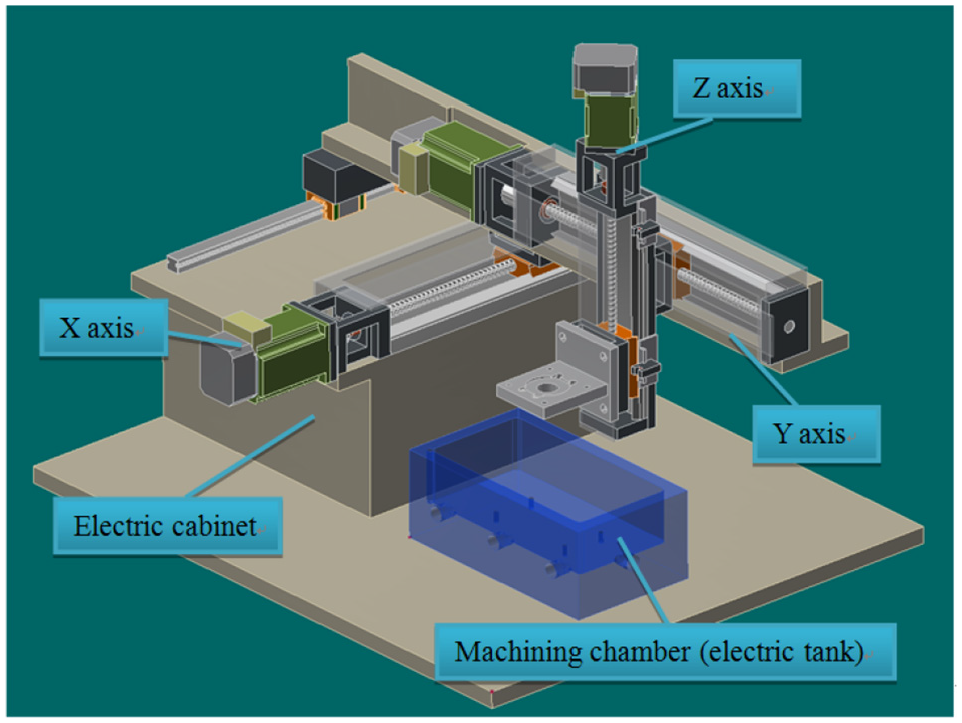
Schematic of mobile tools electrochemical micromanufacturing system.
Machining parameters for the experiments.

Record the average value of the undercut in the each micro-hole experiment and calculate its S/N ratio, then calculate the response table and response graph, and observe the parameters that affect the undercut effect the most, and finally use the analysis of variance to get the variance. The Figure 3 shown that the smaller the mask hole diameter and the thicker the mask, the greater the S/N ratio. This study, the smaller the better in the Taguchi method, which represents that the larger the S/N ratio, the smaller the undercut amount. The reason is the concealment produced by the mask. The smaller the diameter of the mask hole and thicker mask provided the better the concealment.

Response graph of single hole experiment.
Results and discussion
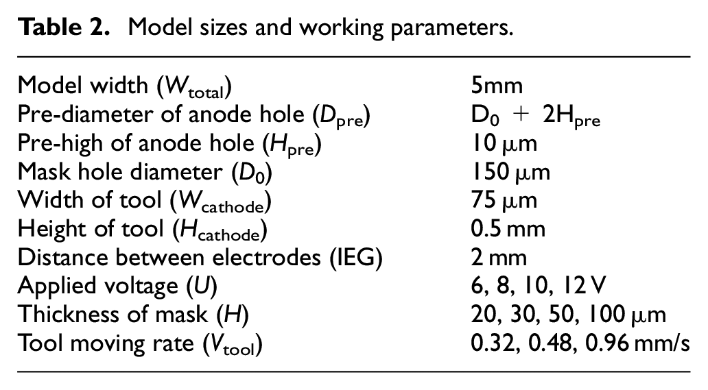
In this numerical simulation, 105,925 grid elements with time step of 0.05 s is verified to yield convergent results. The working parameters are listed as shown in Table 2.
Model sizes and working parameters.
Effect of the applied voltage on the profiles
In this paper, four processing voltage values of 6, 8, 10, and 12 V are selected. The predicted machining shapes of the micro-electrochemical machining with moving tool are shown in Figure 4, and the variations of depth, width, and the aspect factor (depth/width) are shown in Figure 5.

The variation of workpiece shape for different applied voltages.

Variation of workpiece shape parameters for different applied voltages.
Results show that the higher applied voltage was, the higher the machining depth and width were. Since the material removal rate was proportional to the current density, and the local high voltage would lead to local high current density. Figure 3 shows that the higher the voltage the better the aspect ratio, but its value tends to be gentle. As the depth is deeper, the distance between the poles becomes farther such that the forward corrosion rate will slow down. Therefore, the aspect ratio continues to increase, but the increasing rate will be gentler.
Effect of the machining time on the profiles
Figures 6 and 7 show the hole profiles and aspect ratio at applied voltage of 8 V and processing time of 0–10 s, respectively. The processing depth and width increases with time. The EF value increases with the increase of processing time, but its rising slope is gradually slowed down. When the processing time increases, the distance between the two poles will increase and the forward corrosion rate is thus slow down.

Variation of workpiece profile at different machining time.

Variation of shape parameter at different machining time.
The current densities along the workpiece surface in static and dynamic processing at the applied voltage of 8 V are shown in Figure 8. In the static processing, as the processing time increases, the machining depth will also increase. The distance between the two poles will correspondingly increase and it causes the decrease of current density and the forward corrosion rate in the middle part of the hole. However, the current density near the corner is gradually increased all the time. In the case of dynamic machining, when the tool moves toward the processing area, the overall current density gradually increases, and the current density is greatest when the tool approaches the opening hole (processing time is about 4–6 s). When the tool is away from the machining area, the current density gradually decreases. The current density near the corner will also first increase and then decrease due to the electric field changes as the tool tools in the process.

The distributions of current density along the workpiece surface.
The formation of the island-like phenomenon is related to the aspect ratio of the workpiece and the film thickness of the mask. 14 The distribution of current density or electric field for both cases will become uniform gradually as the machining processes. In the static processing, due to the larger tool providing more current density on the workpiece surface, island-like phenomenon is not obvious after the processing of 2 s. On the other hand, in the dynamic processing, due to the small tool providing a small current density on the workpiece surface, the island-like phenomenon will not disappear until a period of processing time. It can thus be concluded that the island-like phenomenon will disappear when the workpiece surface accumulates a certain current density.
Effect of the mask thickness on the profiles
Shenoy and Datta 15 found that the masking effect of the mask affects the etch factor, which in turn affects the directionality and undercut size in the electrochemical process. Mask thickness will affect the distribution of the current density. In this paper, four different mask thicknesses, namely 20, 30, 50, and 100 μm, are used to simulate the effect of mask thickness on the shape of the workpiece. The simulation results of static machining are shown in Figures 9 and 10, respectively. It indicates that the island-like phenomenon occurs near the middle part of the hole and the corresponding aspect ratio of the hole is small as the mask is thin. On the other hand, when the thickness of the mask is thick, the aspect ratio is better and a flat workpiece surface is obtained.

The effect of mask thickness on the shape of machining profile.

The effect of mask thickness on the workpiece shape factors.
Figure 11 shown the current density along the workpiece surface in different time and mask thickness. In the initial stage of machining, the workpiece with a thin thickness of the mask has a large current density concentrated in the corner. In this kind of circumstance, the lateral corrosion is relatively serious, and the island shape is easier to form. When the thickness of the mask is thick, the current density is small and distributed more uniformly in the initial processing stage. When the tool is moved to the machining center (5 s), the shielding effect of the mask is stronger and the current density reaches its largest value. As the tool leaves the machining area, the electric field distribution is still uniform, but the current density gradually decreases.
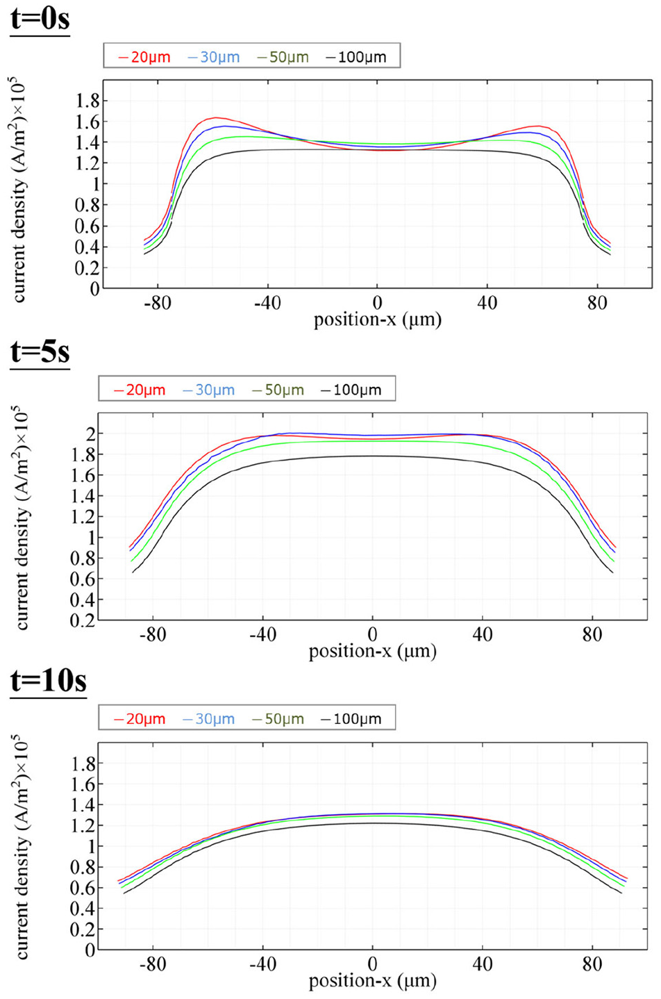
The current density on the workpiece at different time and mask thicknesses.
Effect of the tool movement speed on the profiles
In this study, three different tool movement speeds, namely 0.32, 0.48, and 0.96 mm/s, are used to investigate the effect of tool moving speed on the machining process. The moving distance is kept at the same of 4.8 mm for three cases, that is, the machining is stopped after 15, 10, and 5 s, respectively, such that the tool has moved from left to right position and finishes on swept stroke. The variations of electric field at different time are shown in Figure 12. The effect of tool movement speed on the workpiece profile and shape factor is also shown in Figures 13 and 14, respectively.
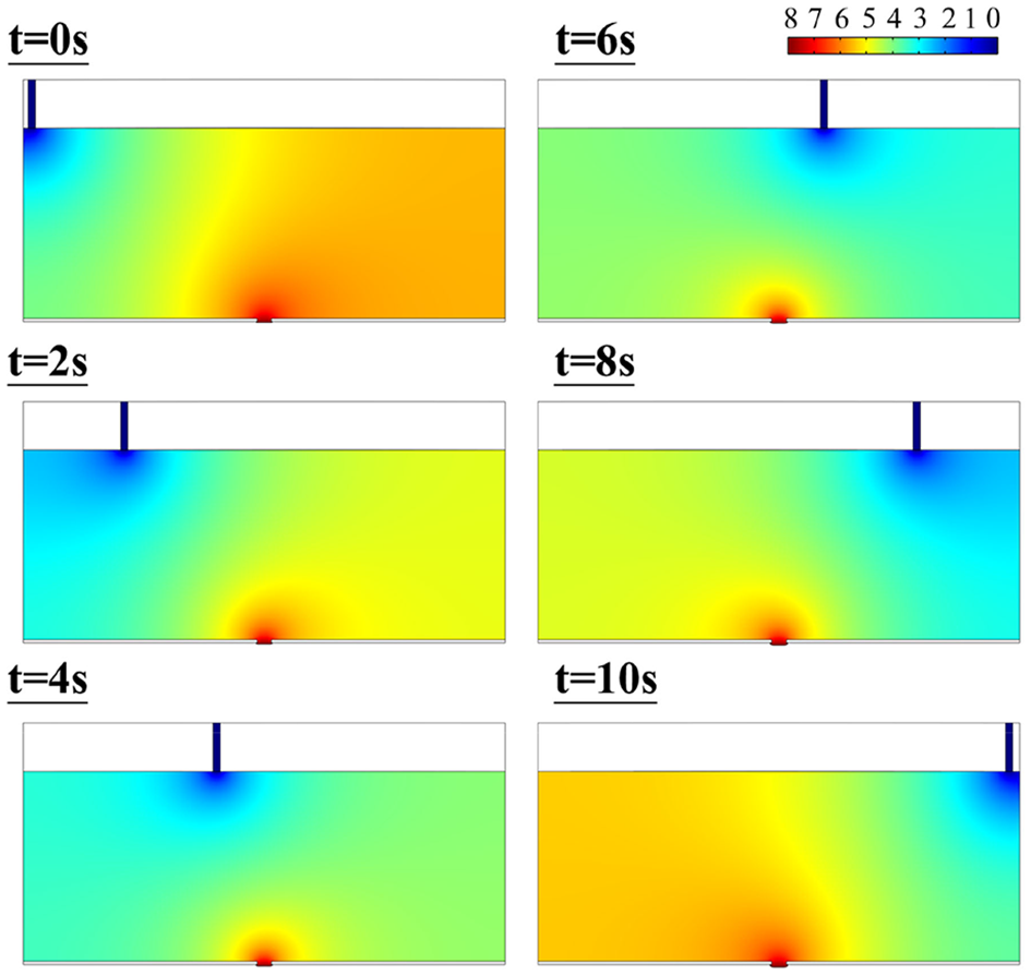
Variation of electric field during the machining process.
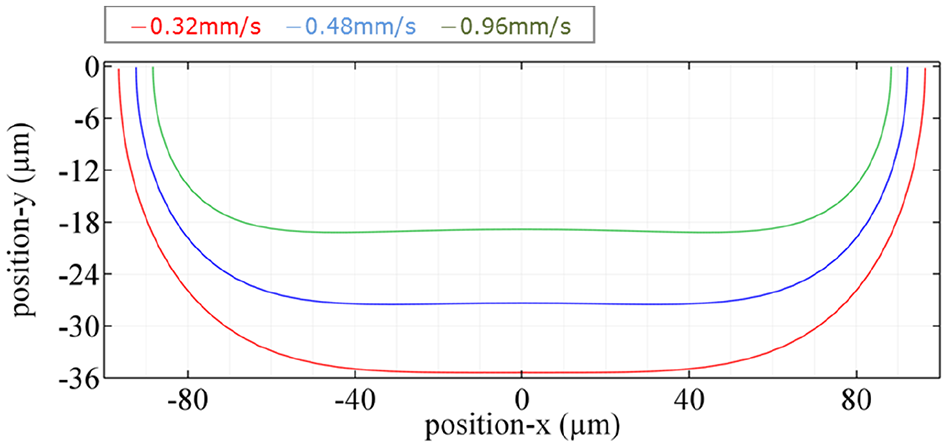
The effect of tool moving rate on the workpiece profile.

The effect of tool moving rate on the workpiece shape factor.
It can be found that the machining depth and hole diameter become large, as the tool moving speed is slow. As the tool moving speed is slow, the processing time is relatively long. The current density along the workpiece surface is thus more, and results in a greater material removal rate. It also can be found that the maximum processing depth occurred in the workpiece center as the tool moving speed is slow. There is no island-like phenomenon, and the depth and aspect ratio are better. On the contrarily, as the tool moving rate increases, the EF value will drop rapidly.
Conclusions
In this paper, COMSOL Multiphysics 5.1 is used to simulate a through-mask micro-electrochemical machining by a moving tool. The influence of parameters, such as applied voltage, mask thickness, and tool moving speed, on machining shape can be drawn as below.
The through-masked micro-electromechanical machining with moving tools can be simulated by finite element method, but in order to explore the undercut phenomenon, the assumption of the preset anode block is necessary.
As the applied voltage is high and moving tool is slow, the processing depth and the diameter of hole are increased. The current density on the workpiece surface is increased, and thus results in a higher material removal rate. However, aspect ratio of the machining tends to be gentle. This is because that, when the machining depth becomes larger, the inter-electrodes will become large and make the forward corrosion rate slow down.
When the mask is thin, the current density distribution is uneven. The island-like phenomenon occurs in the workpiece center, and the aspect ratio is relatively poor. This is due to the shadowing effect of the mask. As the mask is thin, the current density will be concentrated on corner, and make lateral corrosion more serious.
Through the comparison of experimental results and simulation results, the trend of mask affect is quite consistent.
Footnotes
Declaration of conflicting interests
The author(s) declared no potential conflicts of interest with respect to the research, authorship, and/or publication of this article.
Funding
The author(s) received no financial support for the research, authorship, and/or publication of this article.