
Abstract
This article proposes a relative pose estimation method between non-cooperative spacecrafts based on parallel binocular vision. As the information of non-cooperative spacecraft in space is not accessible, the target is considered to be freely tumbling in space. The line feature of non-cooperative target is used to extract the feature points first; then the stereo matching and three-dimensional restructuring are taken for the feature points; finally, an algorithm based on parallel binocular vision algorithm is used to calculate the relative pose between the target coordinate and the world coordinate. The experimental results show that the proposed method has high-accuracy real-time performance.
Introduction
With the development of technology, more than 80–130 satellites are launched into space every year. The fuel running out, system failing, and other problems may lead to satellite failure. 1 To explore the feasibility of repairing the malfunctioned satellite on orbit, Germany, America, and other countries have researched the capture method for the malfunctioned satellites, such as DEOS project and MiTEx system. The research on the three-dimensional (3D) pose estimation is one of the key technologies to ensure the security and reliability of the malfunctioned satellite rendezvous and docking on orbit. 2 The use of vision systems for autonomous landings or pose estimation of aircrafts and spacecrafts has been earlier suggested. 3 An important task of computer vision is to measure 3D pose parameters of one object. When the measurement system comprises two or more cameras, 3D pose parameters can be obtained by intersecting the cameras at three or more feature points on the object. 4
A number of pose estimation methods have been reported. Segal et al.5,6 developed a stereovision-based filtering algorithm for estimating the state between two non-cooperative spacecrafts. Using two cameras mounted on a chaser satellite, the relative state with respect to a target satellite, including the position, attitude, and rotational and translational velocities, is estimated. Du et al. 7 proposed a method based on two collaborative cameras to determine the pose of a large non-cooperative target. The corresponding algorithm of image processing and pose measurement is addressed. Chen et al. 8 and Yu et al. 9 established a binocular stereovision model and proposed a non-cooperative target relative pose measuring method based on stereovision and RANSAC algorithm. Liu et al. 10 proposed a novel method based on multi-feature information fusion to estimate the non-cooperative spacecraft. Xu et al. 11 achieved the target recognition and pose measurement based on the stereovision; the guidance, navigation and control (GNC) of the chaser; and the coordinated plan and control (CP&C) of space robot. According to the most rigid objects’ feature on the ground with the mutually perpendicular or nearly perpendicular planar structures, Lv et al. 12 adopted the normals of planar areas on the target surface to estimate the 3D pose of the target with ladar range image. Sultan et al. 13 proposed a monocular camera vision system for a 6-degree of freedom (DOF) drawing robotic arm to estimate 3D pose of the end effecter robustly. Kirac et al. 14 had demonstrated an implementation of regression forests for estimation of the articulated 3D pose of the human hand. Yu et al. 15 proposed an estimation method of relative pose based on stereovision and Kalman filter, which consists of three parts: body frame reestablishment, translational parameter estimation, and rotational parameter estimation. It is presented for the final phase of the rendezvous and docking of non-cooperative satellites.
Compared with the monocular vision model, the binocular one possesses many merits: the binocular cameras can be used for the data fusion in the stereovision to enhance the robustness of the measuring precision and algorithm; it is free to any designs of the marker, so there is no strict geometric restriction between markers; the binocular cameras can backup information from each other to increase the reliability of measuring results.
In view of the non-cooperative space target, this article proposes a relative pose estimation between spacecrafts. On the basis of the parallel optical axis, this algorithm is relieved from the external calibration of the camera, which is very convenient to the on-orbit service. Taking full advantage of the target line characteristics and extracting the intersection of the associated lines as the feature points, the feature point extraction based on the geometric line feature can reduce the workload of the general epipolar matching. Moreover, the accuracy and stability of the feature points’ extraction are higher in theory.
As shown in Figure 1, we can see that the line feature of the aircraft is very obvious. The tripod to connect the solar array and the aircraft body is a weak part of the whole structure. Once damaged, the tripod must influence the on-orbit operation of the spacecraft. Relative to the other features of the spacecraft, the tripod is a simple structure and an easy identification. So the tripod of spacecraft is selected as the research object. The obtained relative position and attitude of the tripod can be served as the basis for the further relative pose estimation of the whole spacecraft.

Spacecraft model.
The flow chart of pose estimation for non-cooperative spacecraft is as shown in Figure 2.
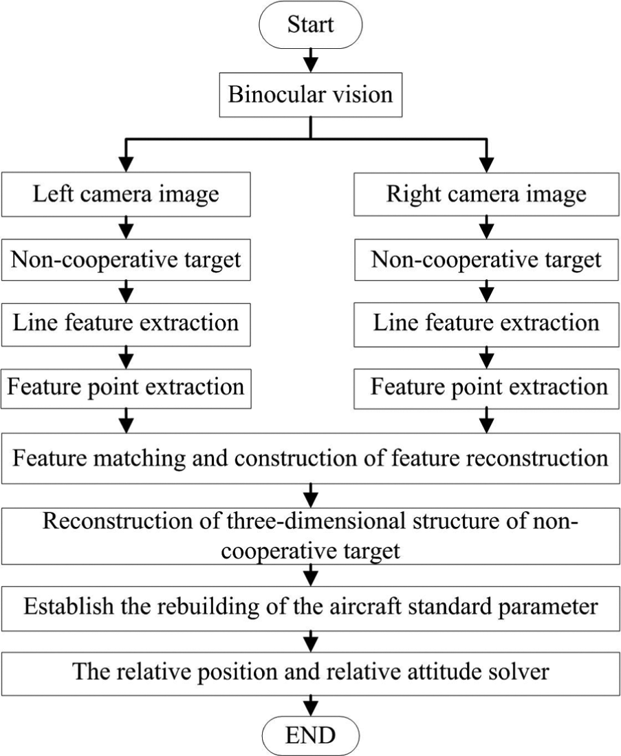
The flow chart of pose estimation for non-cooperative spacecraft.
This article is organized as follows. How to extract the feature point is introduced in section “Feature extraction.” Section “3D relative pose estimation” represents the 3D pose estimation algorithm for space non-cooperative target. In section “Experimental validations,” the semi-physical simulation experiment is conducted to verify the proposed algorithm. The last section summarizes the whole article and gives the conclusion.
Feature extraction
The line feature is the basis of the proposed pose estimation algorithm. We use the line feature extraction to obtain the feature points that are very important to computing the pose parameters. First of all, the high-precision boundary points are extracted by the boundary tracking method. Second, the boundary lines are obtained by the least squares fitting of the boundary points. Finally, the associated line intersections are extracted as the feature points.
Edge feature extraction
Hypothesis that the image area element consists of four adjacent pixels, f(m, m + 1), f(m + 1, n + 1), f(m, n), f(m + 1, n). Use plane ax + by + c to fit four adjacent pixels of the image area element ΔS and use ax + by + c to fit f(x, y); the mean square deviation is
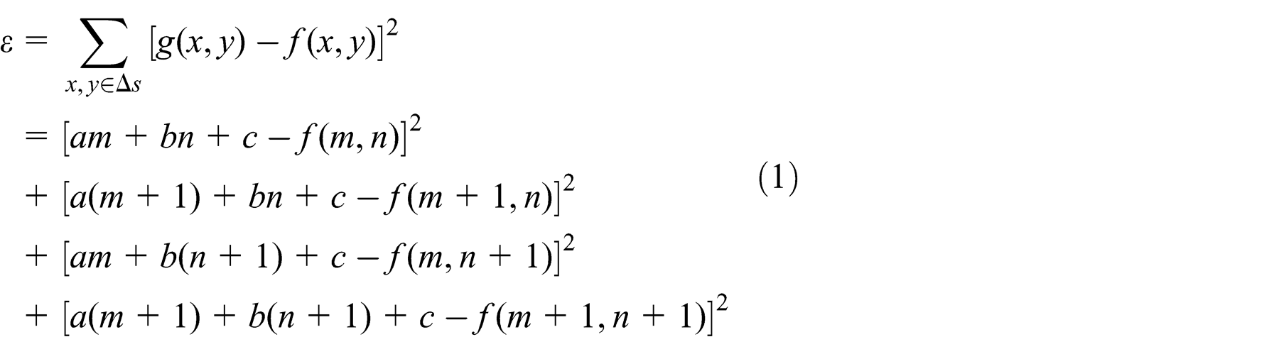
In order to achieve the most optimum anastomosis, the mean square deviation needs to be minimized. The a, b, and c in equation (1) are, respectively, derivations. There are
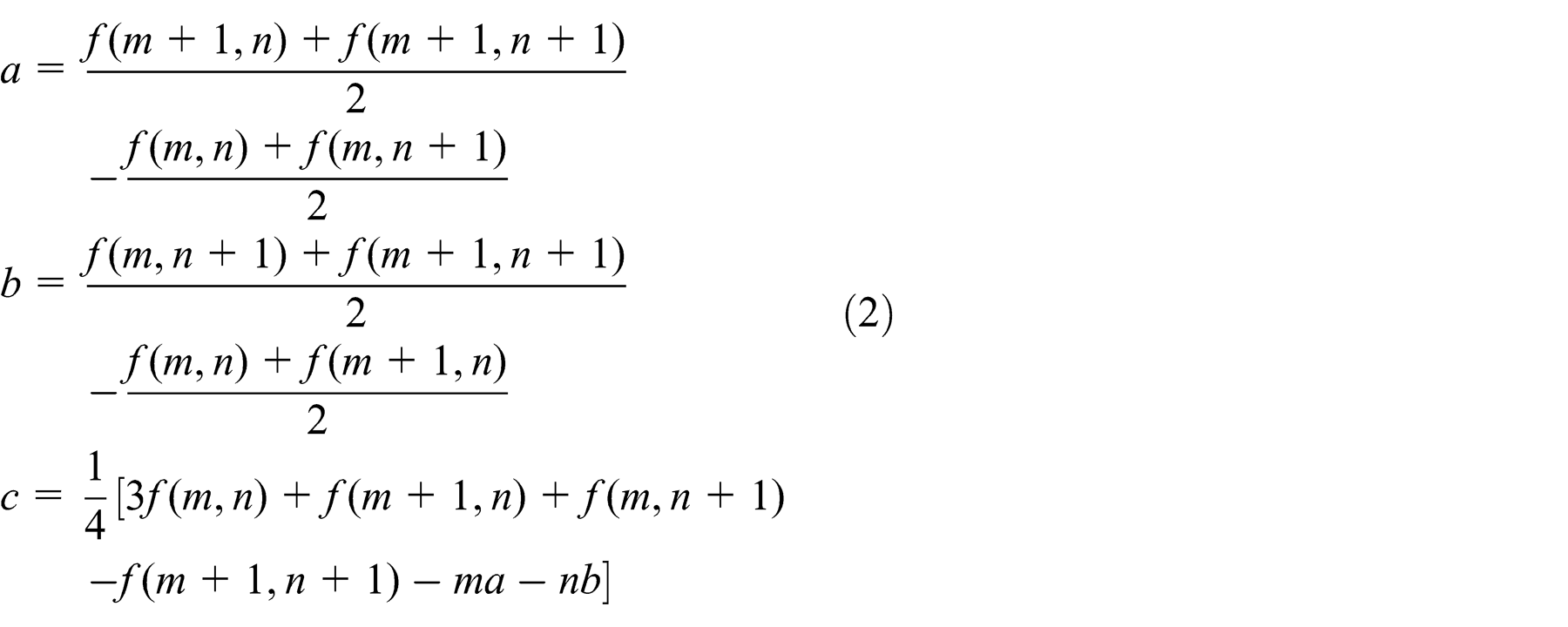
Based on the definition of gradient, the gradient magnitude of the plane ax + by + c is

It follows that a is the difference of the average value between two columns and b is the difference of the average value between two rows. Since the difference is established on the basis of smooth, this method is lower sensitive to the noise compared with the differential operator.
Because the plane is the best approximation of image gray level in the neighborhood of 2 × 2, a plane gradient can be reasonably regarded as the approximation of image gradient values at the neighborhood center point (m + 1/2, n + 1/2). The idea of edge detection based on the surface fitting is to use a plane or curved surface to approximate an image area element. Then, this point gradient is replaced by the plane gradient to implement the edge detection.
According to the principle of the edge feature extraction, the results are as shown in Figure 3.

Edge feature extraction: (a) left image and (b) right image.
Discrete line feature extraction
On the basis of the edge feature’s extraction in “Edge feature extraction,” the discrete line feature is extracted. The starting point for each line can be served as the basis of the line feature extraction.
The criterion for the selection of edge feature can be shown as in Figure 4. The boundary starting points need to be in the eight connected regions. Meanwhile, when turning around the point in clockwise or anticlockwise rotation, there must be three adjoining pixels whose gray value is 0. The pixels marked by “1” are available and the pixels marked by “2” are not available. Following the edge line to track the edge points, the coordinate sequence of the edge points should be given, which is the basic requirement of edge tracking.
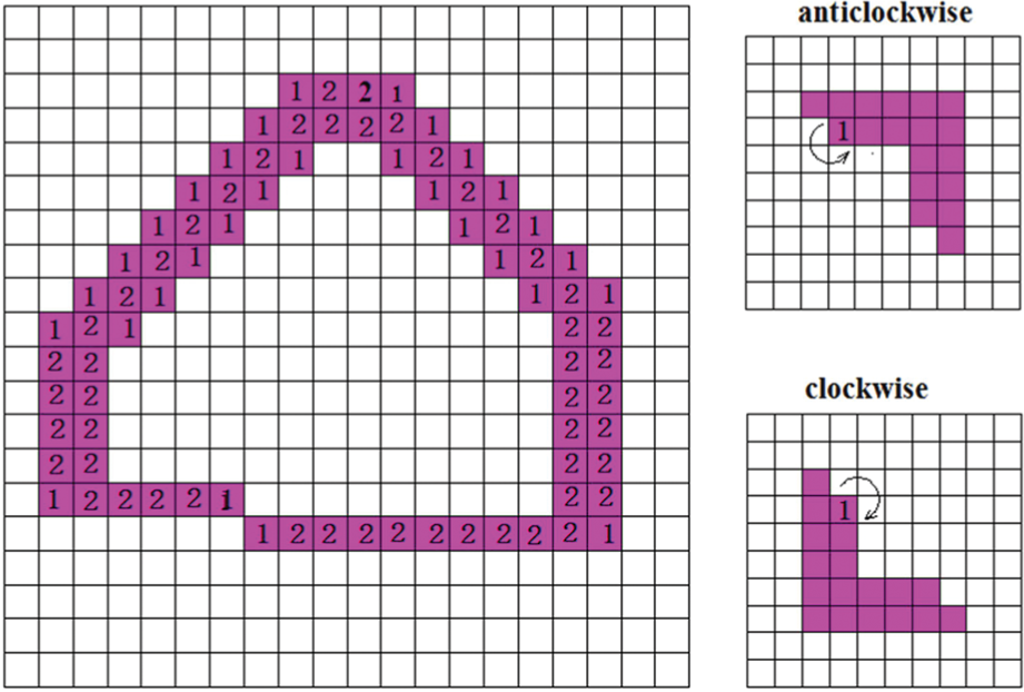
Starting point.
The searching of the edge points’ step is as follows:
Searching the untracked edge points by image-scanning in clockwise direction. The point, if detected, can be defined as the starting point of tracking, recorded as P 0.
Searching the eight adjacent pixel points in a counterclockwise direction, it will turn up to step (c) if the change from the white pixel point to the red pixel point occurs in the position of the next edge point. Otherwise, the starting point tracked would be an isolated point if there is no red pixel in the eight adjacent pixel points, thus the tracking should be over.
Moving forward to the next edge point Pn . If Pn−1 = Pn , Pn = P 1, then the tracking should be over.
The results of the discrete line feature extraction are as shown in Figure 5.

Discrete line feature extraction.
Line feature serialization
A function relationship between x and y by the linear equations y = a 0 + a 1 x. a 0 represents the intercept and a 1 represents the slope. For group N, data precision obtained by measurement of (xi , yi ), i = 1, 2, ..., N, xi value is believed to be accurate, and the error can be linked with yi .
When we use the method of the least squares to estimate the parameters, the yi ’s deviation and sum of squares are to be required for the minimum. The beeline fitting precision of observation is given by

Based on the requirements, the formula should be

After finishing getting normal equations

The equations can be obtained from the best estimation of linear parameters a 0 and a 1

The edge features are the discrete feature points on the boundary. In order to get the edge feature lines, we need the discrete feature points to fit the least squares.
Based on the least squares fitting principle, the discrete feature points are selected to do least squares fitting. The result is shown in Figure 6.

Edge feature.
Extraction and matching of feature points
Based on the least squares fitting, we obtain three edge feature lines on the same plane. By solving three linear equations, we can calculate three intersections of simultaneous pixel coordinates. The results are shown in Figure 7.

Feature points’ extraction.
The epipolar constraint can greatly limit the search range of the corresponding point, especially when the binocular stereovision system is in a parallel alignment configuration. In the system, the x axes of two cameras are the same, so the polar line of image plane becomes parallel lines. Each epipolar equation does not need to be calculated when matching; we only need to scan the image matching the feature points. The flow chart of the extraction and matching of the feature points is as shown in Figure 8.

The flow chart of the extraction and matching.
3D relative pose estimation
As shown in Figure 9, Ot-XtYtZt is the target coordinate and OW-XWYWZW is the world coordinate. The relative pose refers to the position and attitude compared to the reference object. The transformation between the two coordinates can be represented mathematically. Therefore, if we know the coordinate and three non-collinear feature points in two coordinates, we can obtain the relative position and orientation. According to the relationship among various points between object coordinate and world coordinate, we can calculate the relative pose between world coordinate and target coordinate.

Relative coordinate.
3D position in world coordinate
After the completion of the feature matching, the positions of the feature points are rebuilt in the observation coordinates according to the measuring principle based on the stereovision. Thus, 3D structure of the non-cooperation target in space can be reconstructed.
The transformation from world coordinate system to the camera coordinate system: since the world coordinate system is a coordinate system used to describe the illusion of camera position, we can take the binocular vision of the left image to the camera coordinate system as the world coordinate system. In this case, the transformation from the world coordinate in the parallel binocular vision system to the left camera coordinate can be expressed as follows
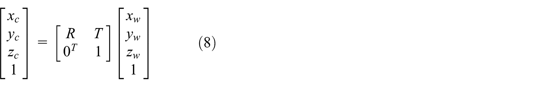
where R is a rotation matrix, and there is no rotation relationship because of the parallel binocular vision of coordinates system. R is an identity matrix, T is a translation vector, and the mold is the base distance b. Because it is in right translation, the calculation should take a negative sign. 0 T is the transverse vector of 0.
The transformation from the camera coordinate to the imaging plane coordinate system: because the model is the pinhole imaging model, the transformation from the camera coordinate to imaging plane coordinate system agrees to the perspective projection, which can be expressed in homogeneous coordinates as follows

In which, f represents the focal length of the camera, (xc , yc , zc ) is the arbitrary P 3D coordinate in camera coordinate system space, and (x, y) is the two-dimensional (2D) coordinate of P in imaging plane coordinate system.
The convention from imaging plane coordinate system to computer image

where (u 0, v 0) is an imaging plane coordinate system origin in the computer image coordinate system coordinates, often taken as the center point of a computer image coordinates. (dx , dy ) are the distance between the pixels adjacent to the imaging plane coordinate system in the x- and y-directions.
Substituting formulas (8) and (9) into formula (10), we can get equation (11)

Setting equivalent transformation as follows

Equation (11) can be abbreviated as follows

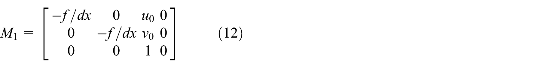
wherein R is a rotation matrix, T is a translation vector, M 1 is the camera internal matrix, M 2 is the camera external matrix, and M = M 1 × M 2 is the camera projection matrix. In the parallel binocular vision system, both cameras are parallel movement and have identified the left camera coordinate system for the world coordinate system, thus the rotation matrix R is a unit matrix and the mold of translation vector is the distance b between the two cameras. Equation (11) can be further simplified into formula (15)
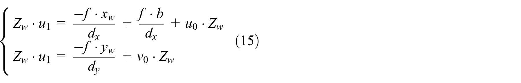
Finishing the above formulas’ calculation between the world coordinate system and the image coordinate system, we can obtain equation (16)

According to equation (16), all the point’s 3D coordinates in world coordinate can be obtained.
Non-cooperative target pose solver
Setting P 2 as the original point, the plane where P 1, P 2, P 3 lies is the x–y plane, X 2 X 3 is the x-axis, y is perpendicular to P 2 P 3, the y-axis positive direction is the same as the world coordinate system, and z-axis is perpendicular to the x–y plane establishing the standard coordinate system, as shown in Figure 10.

The relative coordinate system.
The relationship between the target coordinate and the world coordinate system is

[xw , yw , zw ] T is the coordinate in the world coordinate, [xt , yt , zt ] T is the coordinate in the target coordinate, R is the orthogonal rotation transformation matrix, and T is the translation vector.
Taking the coordinate of P 1, P 2, P 3 in world coordinate system and target coordinate system into formula (17), and combining the feature of orthogonal matrix, then we can get the value of R.
The rotation order is z, x, y. The corresponding rotation angles are γ, α, β. According to the Euler angle method, the parameters can be obtained from the following formula

From formula (18), we can get


Experimental validations
The experiment platform of space control technology mainly contains a 6-DOF platform, a stereo camera, and a motion controller. The spacecraft model on the 6-DOF platform can realize all kinds of accurate poses (Figure 11).

Experiment platform.
The relationship between the vision system and the 6-DOF platform is shown in Figure 12. The pose of the platform is adjusted to the initial status by the motion controller. At this time, all the pose parameters in the coordinate system of the 6-DOF platform (Xp-Yp-Zp ) are 0. By camera calibration, 16 we can obtain the relationship between the initial status of the 6-DOF platform and the vision system. The matrix transform is given in formula (22). R 1 is a 3 × 3 orthogonal rotation transformation matrix, and T 1 is the translation vector

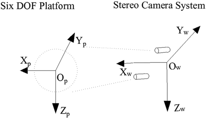
Relationship between stereovision system and 6-DOF platform.
Experiment result
The 3D pose parameters include the position and attitude parameters. The x, y, and z are used to characterize the position information of the target spacecraft in the world coordinate. The yaw, pitch, and roll are used to characterize the attitude angles of the target aircraft relative to the world coordinate.
The experimental results show that the error of relative pose and the distance are linear relationship. The analysis of Figure 13(a)–(c) shows that in the distance from 2 to 4 m, the position errors are close to 0. As shown in Figure 13(d)–(f), in the distance from 1 to 3.5 m, the error of pitch angle is about 1°, the error of yaw angle is less than 1°, and the error of roll angle is less than 0.5°.
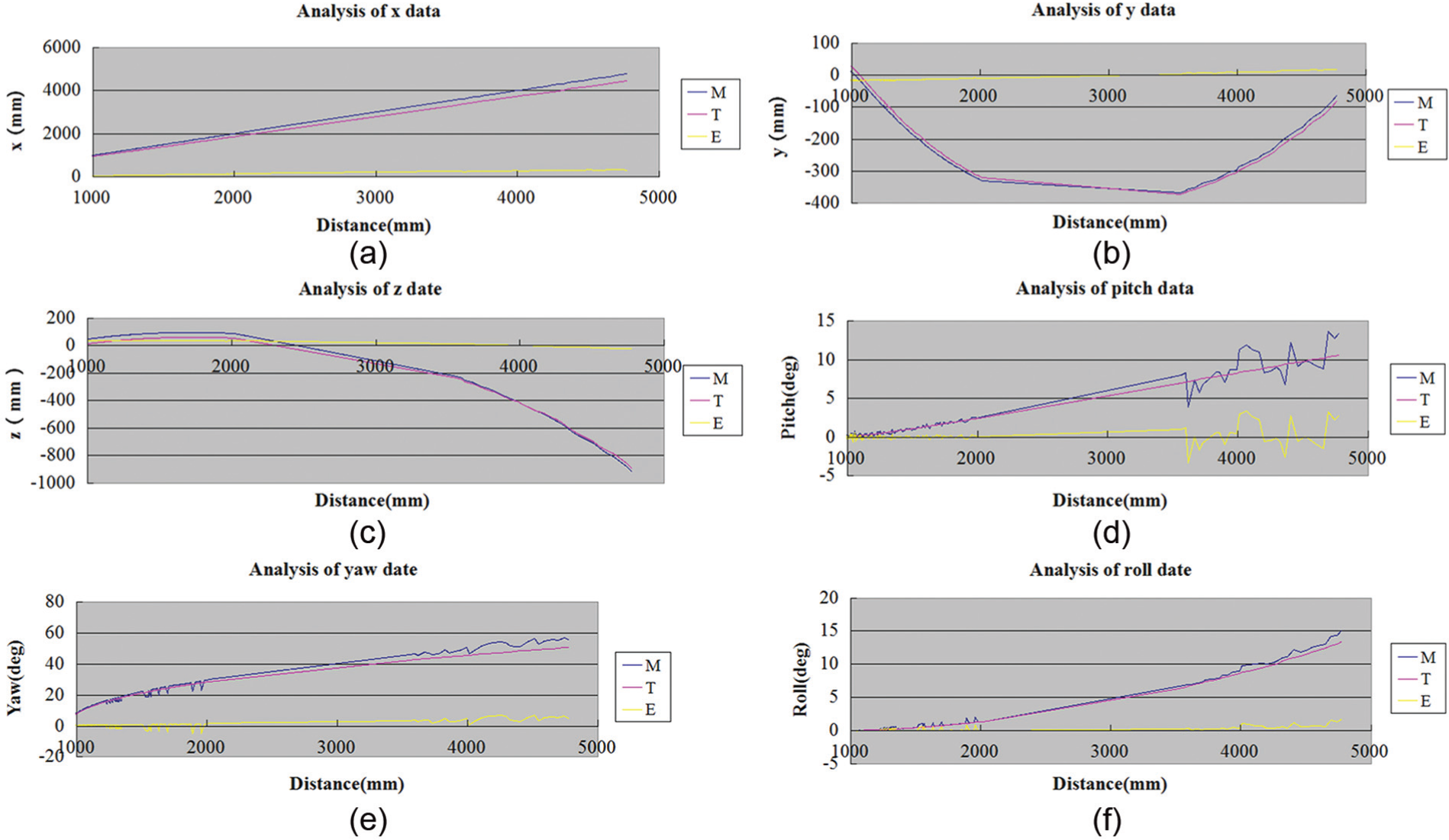
Data analysis: (a) analysis of x data, (b) analysis of y data, (c) analysis of z data, (d) analysis of pitch data, (e) analysis of yaw data, and (f) analysis of roll data.
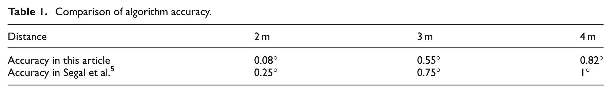
Comparison with existing method
The experiment results in Segal et al. 5 show that the accuracy of the relative position estimation can be up to 0.02 m, and the accuracy of the relative attitude estimation can be within 2°. The accuracy of the proposed algorithm is significantly higher than that in Segal et al. 5 Especially in the distance, there are more obvious advantages in the proposed algorithm. The attitude accuracy comparison in the same distance is shown in Table 1.
Comparison of algorithm accuracy.
Conclusion
This article proposes a stereovision-based method to estimate the relative pose between non-cooperative spacecrafts. The surface fitting method is applied to detect the edge of the object. The lines are fit by the points on the edge. The intersections of the lines are taken as the feature points of the object. The matching of the feature points between the two images is based on the epipolar geometry relationship. Since the parallel vision-based system is adopted, the external camera parameters need not be calibrated in the process of the 3D reconstruction. The 3D pose parameters of the spacecraft are estimated by the relative coordinate values in world coordinate and object coordinate. The accuracy of the method is validated on the experiment platform of space control technology and the results show that the higher accuracy is the advantage comparing with the existing algorithm.
Inheriting this article’s work, the future work will concentrate on the speed of the algorithm to achieve a real-time system.
Footnotes
Academic Editor: Yangmin Li
Declaration of conflicting interests
The authors declare that there is no conflict of interest.
Funding
This wok was supported by Scientific Research Project of the Education Department in Liaoning Province (No. L2013198) and National Nature Science Foundation of China (No. 51305055).