
Abstract
The proposed three-dimensional pose estimation model for object with complex surface, which primarily absorbs the essence of scale-invariant feature transform and iterative closest point algorithm, includes two steps, off-line and online. At first, two kinds of feature databases are established in the off-line operations. Then, the online process mainly has three steps. The first one is two-dimensional edge extraction from red–green–blue (RGB) information based on scale-invariant feature transform algorithm. The second one is three-dimensional surface reconstruction from the previous two-dimensional edge and the depth information obtained from depth camera. The last one is three-dimensional pose estimation based on camera calibration and iterative closest point algorithm. The Kinect camera is selected as the information acquisition device which can produce red–green–blue information and depth information. In the experiment, the container twist-lock with complex surface is taken as the object. The result shows that the accuracy of the proposed model is very high.
Keywords
Introduction
Three-dimensional (3D) pose estimation is one of the current important studies and is very useful in many fields. Shai Segal et al. 1 estimate the relative 3D pose of the cooperative satellites by on-board sensors to be used for the spacecraft formation flying or rendezvous and docking. Dan Lv et al. 2 achieve a 3D pose estimation model for the rigid objects on the ground to recognize the military vehicles automatically. Malik Saad Sultan et al. 3 propose a monocular camera vision system for a 6-degree-of-freedom (DOF) drawing robotic arm by estimating the 3D pose of the end effecter robustly. Furkan Kirac et al. 4 detect the 3D pose of hand gesture from single frame depth data to realize the human–computer interaction.
The research on 3D pose estimation belongs to a multi-interdisciplinary area, involving the projection geometry, digital image processing, computer graphics, computer vision, and many other disciplines. 5 The 3D reconstruction is the key technology of this research to restore the 3D space information of the objects through the basic elements (such as points, lines, and planes) from two-dimensional (2D) images. For achieving the quantitative analysis of the scale and positions of the objects, it also needs to study the relations between 3D coordinates of points, lines, and planes in 3D space and the corresponding ones in 2D images. The 3D information or 3D model is obtained by feature extraction, feature matching, reconstruction of key characteristics, triangulation, and data fusion.
The proposed model is investigated using Kinect camera produced by Microsoft Corporation. The software development kit (SDK) of the camera is open to the users. 6 Moreover, it has the ability to provide the depth information for every red–green–blue (RGB) pixel acquired. It is possible to build 3D point clouds using the depth information, which are very suited for 3D reconstruction and frame-to-frame alignment.7–9 Furthermore, RGB data can be more appropriate for other processes such as loop closure detection. 10 Combining both characteristics seems to represent an opportunity to develop more on robotics navigation or object recognition. 11
The general architecture of the model is shown in Figure 1, which primarily absorbs the essence of scale-invariant feature transform (SIFT) and iterative closest point (ICP) algorithm. It totally has two steps, off-line and online. At first, two feature databases are established to simulate the human memory in the off-line operations. Then, the online process mainly has three parts: (1) 2D edge extraction from RGB information based on SIFT algorithm; (2) 3D surface reconstruction from the previous 2D edge and depth information obtained from depth camera; and (3) 3D pose estimation based on camera calibration and ICP algorithm.
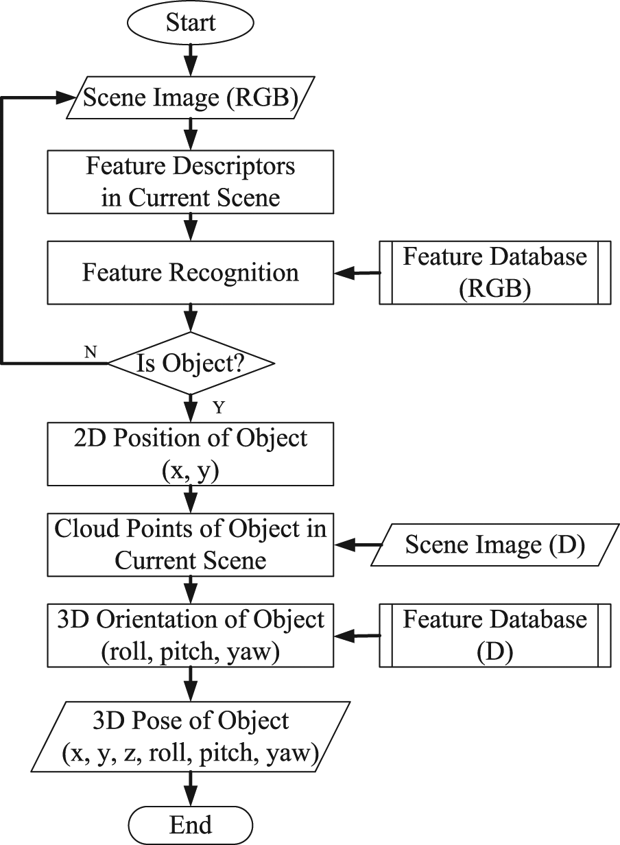
General architecture of proposed model.
The SIFT descriptor proposed in Lowe 12 could keep the feature invariant after being rotated, resized, and even affined. The SIFT algorithm detects the feature in the scale space whose orientation is the principal direction of the neighborhood gradient. The SIFT algorithm has been continuously improved to achieve a higher stability.13,14 The process of obtaining the SIFT descriptors includes five steps: detection of scale-space extrema, accurate key point localization, orientation assignment, generation of feature descriptors, and matching regulation.
ICP 15 is an algorithm employed to minimize the difference between two sets of point clouds. ICP is often used to reconstruct 2D or 3D surfaces from different scans and to localize robots and achieve optimal path planning (especially when wheel odometry is unreliable due to slippery terrain). The algorithm is conceptually simple and is commonly used in real time. It iteratively revises the transformation (translation, rotation) to minimize the distance between the points of two raw scans.
In the experiment, the container twist-lock with complex surface is taken as the object. The important significance is that the robotic technology is needed to replace the stevedores’ heavy work to improve the efficiency and safety. At the same time, the twist-lock and corner casting together form a standardized rotating connector for securing shipping containers by coupling containers together during transferring. Each container needs at least four twist-locks, and there are many twist-locks to be used in the world. All of them are removed and installed by manual work now.
The rest of this article is organized as follows: the feature databases are established in off-line operations in section “Establishment of feature database in off-line operations”; section “2D edge extraction from RGB information based on SIFT algorithm” explains how to extract 2D edge from RGB information based on SIFT algorithm; in section “3D surface reconstruction from the 2D edge and depth information,” 3D surface is reconstructed from the 2D edge and depth information; in section “3D pose estimation based on camera calibration and ICP algorithm,” 3D pose parameters (x, y, z, roll, pitch, yaw) are computed based on the camera calibration and ICP algorithm; the experimental results are given in section “Experimental validations” to show the feasibility and performance of the proposed algorithm; finally, a brief conclusion and future work is presented in section “Conclusion and future work.”
Establishment of feature database in off-line operations
Two kinds of feature databases are established in the off-line operations. One is the RGB feature database and the other is the point clouds database.
RGB feature database
The ideal RGB database is established to simulate the human memory as follows: first, the target is placed at the center of the regular polyhedron, and then, the images are acquired by some cameras, which are fixed on the centers of the polyhedron surfaces and while the optical axes of the cameras are in coincidence with the normal lines of the polyhedron. The more surfaces can make the object feature and the recognition performance better; however, it will make the algorithm more complex. Considering the complexity and precision, the octahedron is adopted in the experiment.
The eight images from different viewpoints need to be processed. Each feature image is described by two matrixes, which are the descriptors matrix and the location matrix, respectively. The descriptors matrix is a K-by-128 matrix, where each row gives an invariant descriptor for one of the K key points. The descriptor is a vector of 128 values normalized to unit length. The location matrix is a K-by-4 matrix, in which each row has the four values for a key point location (row, column, scale, and orientation). The establishment of feature database is off-line in order to save online resources. As shown in Figure 2, the descriptors of one feature image are displayed by arrows. The direction of the arrow represents the direction of the gradient in the position of the corresponding pixel; the length of the arrow represents the module of the gradient.

Descriptors of one feature image.
Point clouds database
The point clouds database is used in the ICP-based process. It is acquired in the standard state. At this time, the 3D pose parameters are x = 500, y = 0, z = h (h is the highest point on the surface), roll = 0, pitch = 0, and yaw = 0, respectively, as shown in Figure 3.

Point clouds database.
2D edge extraction from RGB information based on SIFT algorithm
Detection of scale-space extrema
The scale-space theory is used to describe the multi-scale characteristic of one image. The Gaussian Convolution Kernel is the only linear kernel to achieve the scale transform; therefore, a 2D scale space is defined

where

The Difference of Gaussian (DoG) scale space is proposed in order to detect the stable critical point in the scale space effectively. The DoG is easy to be calculated, which is close to the scale-normalized Laplacian of Gaussian (LoG) operator

In order to find out the extreme points in scale space, each sampling point should compare with all the adjacent points. As shown in Figure 4, the middle detected point compares with the other adjacent points, which include the 8 ones in the same scale and the 18 ones in the adjacent scales.

Sampling point comparing with all the adjacent points.
Accurate key point localization
In order to enhance the stability and improve the noise immunity, the location and scales of the key points (to achieve sub-pixel accuracy) are accurately determined through fitting 3D quadratic function; meanwhile, the low-contrast points and instability edge points are removed.
The extreme value of badly defined DoG operator has a greater principal curvature across edge compared with a smaller curvature in the vertical edge direction. The principal curvature can be derived by a 2 × 2 Hessian matrix H. The derivatives in H are estimated by the differences of the adjacent sampling points.

The principal curvature of D is proportional to the eigenvalues of H. Let


Let

The value of

Orientation assignment
The direction parameters are assigned to every critical point according to the distribution property of the neighborhood pixels’ gradient direction to make the operators have the rotation invariance. The following formulas are the module and direction of the gradient at (x, y)


In practice, the sample process is carried out in the neighborhood window which takes the critical point as the center, while uses the histogram to count the gradient direction of the neighborhood pixels. The histogram range is 0°–360°, hereinto, every 10° are considered as a column. The peak of the histogram represents the principal direction of the neighborhood gradient at this critical point.
In the histogram, other directions, whose peak value is more than 80% of the principal peak value, are considered as the auxiliary directions. The use of auxiliary directions can enhance the robustness.
At this time, the key points have been detected completely. Each point has three parameters: position, scale, and direction.
Generation of feature descriptors
Above all, the coordinate axis rotates to the direction of the critical point to ensure the rotation invariance. Then, the 8 × 8 window is obtained, which takes the critical point as the center. As shown in Figure 5(a), the black point is the critical point, each grid represents a pixel, the direction of the arrow represents the direction of the gradient in the position of the corresponding pixel, the length of the arrow represents the module of the gradient, and the blue circle represents the Gaussian-weighted scope.

Feature descriptors. (a) Gradient of adjacent pixels. (b) Feature descriptors by gradient synthesis.
Afterward, the gradient histogram that has eight directions is calculated in each 4 × 4 block, as shown in Figure 5(b). The cumulative value for each gradient direction forms a seed point. In this method, a key point is expressed by four seed points, while every seed point has eight directions.
Match regulation
The SIFT feature descriptors of the twist-lock in scene and the eight feature images have been generated. Then, by the Euclidean distance we can obtain eight similarity values, which are the quantity of the matching points between the twist-lock and the feature database. The biggest value of them is effective. Simultaneously, the psychology threshold is set. If the biggest value is greater than the psychology threshold, the region is considered as the corresponding object.
Experimental evaluation
The code is realized according to the above-mentioned model. A lot of experiments have been made to test the algorithm. As shown in Figure 6, the 2D edge can be extracted. The result indicates that processing accurately one color image digitized at 640 × 480 resolutions takes 200 ms online (Intel(R) Pentium(R) 4 CPU 3.00 GHz, 1.00 GB of RAM Physical Address Extension).
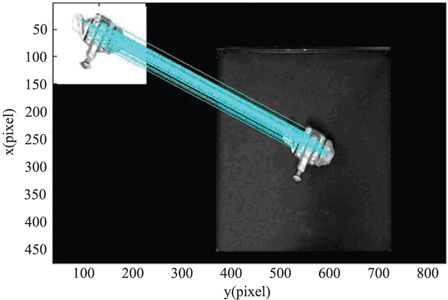
Result obtained by the SIFT algorithm.
3D surface reconstruction from the 2D edge and depth information
The 3D surface data can be obtained from the previous 2D edge and depth information. We can get the projective data in 3D coordinate (Figure 7(b)) from the original depth image (Figure 7(a)). In Figure 7(a), the bar on the right shows the pseudo-colors corresponding to the depth value, whose unit is millimeter. The zero level is the surface of the experiment table. We can see that the data are very noisy. How can we find 3D data of the object? We resort to the 2D edge (Figure 7(c)) for solution. After matching, the 3D surface can be reconstructed as shown in Figure 7(d).
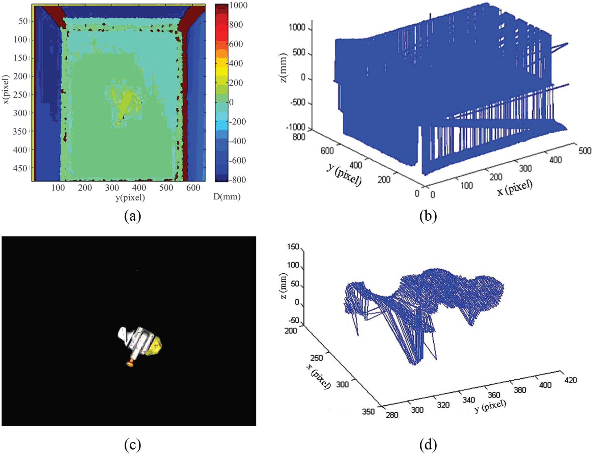
Three-dimensional (3D) surface reconstruction: (a) original depth image, (b) projective data in 3D coordinate, (c) 2D edge of object, (d) actual points cloud in pixel coordinate.
3D pose estimation based on camera calibration and ICP algorithm
The 3D pose array includes three position parameters (x, y, z) and three orientation parameters (roll, pitch, yaw). As shown in Figure 8, Oo-XoYoZo is the object coordinate and OW-XWYWZW is the world coordinate. On the basis of the previous result, the 3D pose parameters can be computed by camera calibration and ICP algorithm.

Three-dimensional (3D) pose definition.
2D position by camera calibration
So far, the position of the twist-lock is obtained in the pixel coordinate system. After that, we need to transform this position into the real-world coordinate by camera calibration 16 (Figure 9). The transformation data from pixel coordinate to world coordinate are shown in Figure 10.

Camera calibration.

Coordinate transformation. (a) Actual points cloud in pixel coordinate. (b) Actual points cloud in world coordinate.
Orientation estimation based on ICP
Introduction of ICP
The ICP algorithm is given by Besl and McKay 15 in 1992. In general, ICP has to select some sets of points in one or both meshes and matches points to the samples in the other set. Meanwhile, a definition for errors is assigned and the errors are minimized by the iteration. The model shape can be a set of points, plotlines, parametric curves, implicit curves, or implicit surfaces.
ICP algorithm moves a data shape P to align with a model shape T. Let Q be the resulting set of points and c be the closet point operator

Given the result set Q, which is the correspondence of P and T, the least-squares registration is computed by

Transform every point of P by matrix H

A set of points S from the data shape to the model shape T is given. Let S and T represent source and target data shape, respectively. Iteration is initialized with
Step 1: compute the closest points by equation (11)

Step 2: estimate the transformation parameters using a mean-square cost function by equation (12)

and make the distance
Step 3: transform the points using the estimated parameters by equation (13)

Step 4: terminate the iteration when the change in mean-square error falls below a threshold
Given 3D shape from point clouds database and a 3D shape in the actual state, the ICP will get the optimal solution if the “actual data” set is the subset of the “point clouds database.” However, a copy of a 3D parametric spine is rotated to be difficult to match the reference if the 3D shapes are built from different directions, which only partially overlap between each other. As a result of that, the initial relative pose estimation should not be too different from the real one.
Orientation estimation
We can obtain the refined transformation (rotation matrix and translation matrix) from point clouds database to 3D shape in actual state.
The yaw, pitch, and roll rotations can be used to place a 3D body in any orientation. A single rotation matrix can be formed by multiplying the yaw, pitch, and roll rotation matrices to obtain

Suppose an arbitrary rotation matrix

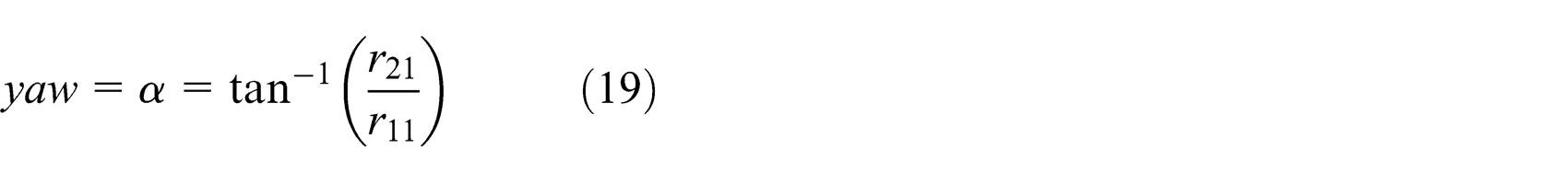
is given. By setting each entry equal to its corresponding entry in equation (17), the equations can be solved for


Experimental validations
Experimental platform and software
The experimental platform in Figure 11 is composed of one experiment table with the steadier apparatus, one main machine and expanded monitor, one Kinect camera, and one ABB robot. The 3D pose estimation software, which is developed by our group, can integrate all the previous algorithms. The interface of the 3D pose measurement software is as shown in Figure 12.

Experimental platform.

3D pose estimation software.
Experimental result
The main experimental flow is published to carry on the analysis, as shown in Figure 13. The object to be searched for is a twist-lock.

Main experimental flow.
Figure 14 shows the RGB-D images in the typical scenes. The first scene is that there is only the smaller rotation of z (yaw), whose direction is positive. There is also only the rotation of z (yaw) in the second and third scenes; however, the rotation is larger in the second scene and the direction is negative in the third scene. Meanwhile, there is only the rotation of y (pitch) in the fourth scene, and there are the rotations of x (roll) and y (pitch) in the fifth scene. Moreover, the rotations of three axes exist in the sixth scene.

RGB-D images in the experiments: (a) RGB-D images in first scene, (b) RGB-D images in second scene, (c) RGB-D images in third scene, (d) RGB-D images in fourth scene, (e) RGB-D images in fifth scene, and (f) RGB-D images in sixth scene.
The matched experimental results are shown in Table 1. “T” represents the true value, “M” represents the measured value, and “E” represents the error value. The unit of x, y, and z is millimeter, and the unit of roll, pitch, yaw is degrees. All of them denote that the accuracy of the proposed model is very high.
Experimental result.
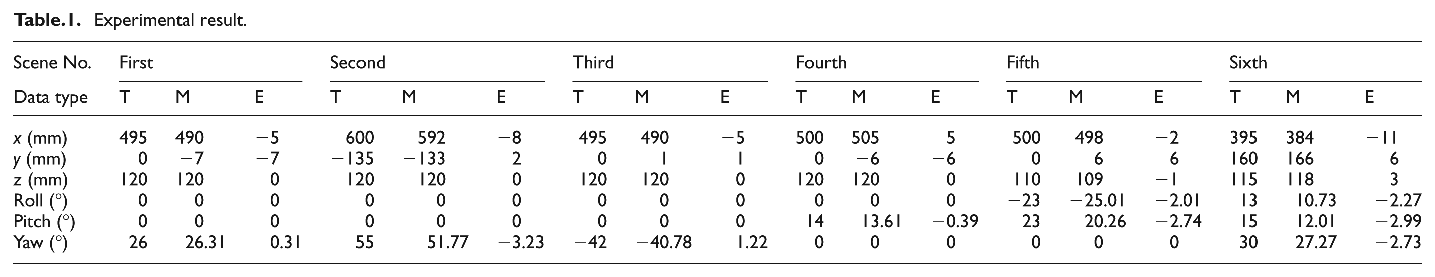
The result indicates that processing accurately one scene takes about 1.5 s online (Intel(R) Pentium(R) 4 CPU 3.00 GHz, 1.00 GB of RAM Physical Address Extension). Since the twist-lock to be recognized is stationary in the actual application, this speed of the proposed model can meet the requirements of the robot grasping very well.
Conclusion and future work
Inspired by the SIFT and ICP algorithm, a 3D pose estimation model is proposed for object with complex surface, which includes both the off-line step and the online step. The off-line step includes the RGB database used for SIFT and the point clouds database used for ICP. The online process mainly has three steps, which are 2D edge extraction from RGB information based on SIFT algorithm, 3D surface reconstruction from the previous 2D edge and the depth information obtained from depth camera, and 3D pose estimation based on camera calibration and ICP algorithm. The Kinect camera and the container twist-lock are selected, respectively, as the information acquisition device and the recognized object. The result shows that the accuracy is very high.
Inheriting this article’s work, the future work will concentrate on the cooperation with gripping robot. Moreover, the ICP used in this article is time-consuming, so the speed of the algorithm needs to be improved to meet the requirements of grasping a dynamic object and then to achieve a real-time system.
Footnotes
Academic Editor: Xiaotun Qiu
Declaration of conflicting interests
The authors declare that there is no conflict of interest.
Funding
This work was supported by Scientific Research Project of the Education Department in Liaoning Province (No. L2013198) and National Nature Science Foundation of China (No. 51305055).