
Abstract
This paper deals with the problem of relative pose determination between a model-known uncooperative space target and a chaser spacecraft using three-dimensional point cloud. A novel, reliable and real-time relative pose determination framework is proposed, which is composed of a region of interest–based initial pose acquisition method and a template matching iterative closest point algorithm for tracking pose. The initial pose is obtained by the principal component analysis method which aligns the region of interest extracted from the scanning point cloud with the region of interest of the known model point cloud, and a three-dimensional convex hull is constructed to extract the region of interest fast. To improve the iterative closest point, the registration between the template point cloud generated by the pose of last frame and the point cloud of the current frame is used to replace the registration between the local scanning point cloud and the global model point cloud. In addition, the performance (stability, low cost and their robustness against noise) of the proposed initial pose acquisition method and the accuracy and reliability of the pose tracking algorithm have been demonstrated by the numerical experiments. Finally, the effectiveness of the proposed method is verified by the field experiment.
Keywords
Introduction
The relative pose determination in the aerospace field computes the relative position and attitude between the chaser spacecraft and the target spacecraft. As one of the critical technologies for many advanced space applications, like on-orbit servicing (OOS)1,2 and active debris removal (ADR),3,4 the relative pose determination algorithm has been successfully applied to the projects5–7 between two cooperative spacecrafts, which are equipped with auxiliary equipments such as marker and answering machine.
However, most of the spacecraft of the on-orbit service and space debris are uncooperative targets without available auxiliary markers or communication devices, which brings great challenges to the pose determination between the chaser and uncooperative targets and has been frequently concerned by the majority of researchers. The method of the pose estimation depends on the type of sensors installed on board of the chaser spacecraft. Such sensors can be monocular vision, 8 stereo vision 9 and Light Detection and Ranging (LiDAR).10,11 Due to the robustness in the variable illumination conditions, various types of LiDAR, such as scanning LiDAR and Flash LiDAR, have become the dominant types in the research field of the pose determination of uncooperative targets. 12
In this paper, a fast and accurate initial pose estimation algorithm based on region of interest (ROI) extraction is proposed for the uncooperative spacecraft using the three-dimensional (3D) point cloud obtained from Flash LiDAR or scanning LiDAR. Due to the speed requirement, the 3D convex hull method is used to assist in extracting ROI. In addition, the PCA (principal component analysis) method 13 is adopted to obtain the initial pose. In the pose tracking step, a stable strategy for judging the correctness of the initial pose is proposed first. Aiming at the phenomenon of error increase in registration between the whole model point cloud and the local scanning point cloud in pose tracking, the template matching iterative closest point (TM-ICP) method is proposed which matches the scanning point cloud and the template point cloud generated by the pose of last frame using the ICP algorithm. And the effectiveness of the proposed method is verified by extensive numerical and field experiments.
The rest of this paper is organized as follows. In the “Related work” section, the related work in recent years is described in detail. In the “ROI-based algorithm for relative pose determination” section, the details of proposed relative pose estimation method are presented. The “Pose tracking” section describes the pose tracking stage. Finally, numerical and field experiments and conclusions are shown in the “Experiments” and “Conclusion” sections, respectively.
Related work
Uncooperative targets are usually divided into two categories. One has known geometrical information about their shape and size at least, and the other is fully unknown. In the following step, we provide a brief overview of the relative pose determination for the model-known uncooperative target, which exists in large numbers in space. The process of pose estimation for the model-known uncooperative target is generally divided into the initial pose acquisition stage and the pose tracking stage.8,14,15
The initial pose acquisition for the model-known uncooperative target aligns the acquired data with the target model, which is built as model point cloud, templates or complex features, corresponding to the point-based algorithm and the feature-based algorithm. A 3D binary template matching (TM) algorithm is presented in Greenspan and Jasiobedzki. 10 It divides the 3D template points into grid elements called voxels, and quantifies the occupied voxel as a value of 1 and an empty voxel as a value of 0.
Opromolla et al. 14 build the 3D point template either off-line or directly on board by sampling the attitude parameter space with a fixed angular step and estimate the relative position by means of the centroiding approach. These algorithms take up the amount of on-board data storage or highly computational time (tens of seconds), which is not available for uncooperative spacecrafts with a high tumbling rate. To optimize computational efficiency and restrain the amount of on-board data storage, a PCA-based online TM algorithm is proposed. 16 Similar to Greenspan and Jasiobedzki, 10 the PCA algorithm is used to estimate the main axis of the target, which can resolve two rotational components of the target pose around the other two axes. The remaining unresolved rotation around the target main axis finds the best match by generating templates online. The performance of these techniques has been assessed by means of numerical simulations.
The methods proposed by Ruel et al.15,17 are to store the pairs of points and their associated topological information to trade space for time. The corresponding relationship between the model and the scanning point is found by looking for corresponding polygons or congruent tetrahedron composed of pairs of points, and then the initial pose parameters are estimated. Such methods attributed to the fast lookup capabilities of the hash table are available in real time.
In addition, there are some feature-based approaches that store features extracted from the model off-line, for example, the 3D semi-global descriptor OUR-CVFH (Oriented, Unique, and Repeatable Clustered Viewpoint Feature Histograms). 18 Based on this feature, Woods and colleagues11,19 presented an OUR-CVFH algorithm for the initial pose estimation of uncooperative targets, and the high correctness and the low time complexity of the algorithm are verified by simulation experiments. However, the accuracy and stability of feature extraction from point cloud are usually sensitive to noise.
Without storing features extracted from the model, templates or other topological information of points, the Globally Optimal ICP (Go-ICP) algorithm 20 only needs to store the model point cloud directly. It is the first globally optimal solution to Euclidean registration of two 3D points that is applied to the initial pose estimation of uncooperative targets. While the Go-ICP method takes a long time (tens of seconds at 500 points) to reduce the translation domain, Liu et al. 21 use PCA to calculate the axis-aligned bounding box (AABB) to obtain the new domain and then use the Go-ICP algorithm to search in the 3D space.
Man-made targets often have obvious geometric shapes, such as cylinders, cones, and rectangles. Martínez et al. 22 detect the cylinder body of the uncooperative rocket and project the point cloud onto the axis of symmetry to obtain the barycenter. The initial attitude is obtained by the relative position among the detected nozzle, side tanks, and fairing of target. Inspired by this, and taking into account the structural characteristics of satellites, this paper proposes a real-time method based on the ROI for some man-made spacecraft with large plane features, which only needs to store the model point cloud, and has higher success rate (SR), accuracy and noise resistance.
After acquiring the initial pose, it will be necessary to further refine the pose by applying the iterative closest point (ICP) algorithm which refines the pose in a continuous parameter space by minimizing an error metric iteratively23–25 or bounded Hough transform (BHT)26,27 operating in the discrete domain and effectively trades off reduced precision for increased efficiency. For the ICP method in the pose tracking stage, the error will gradually increase—one of the reasons for this is the wrong correspondence between the model point cloud and the local scanning point cloud. In this paper, the TM-ICP method combining the TM and ICP algorithm is presented to solve this problem effectively.
The proposed method for initial pose acquisition in this paper is a point-based method too. And the relative pose is estimated by aligning the ROI extracted from the model point cloud and the scanning LiDAR point cloud. The strategy combined with ICP and TM is adopted to track pose.
ROI-based algorithm for relative pose determination
The flow of proposed method for determining the relative pose between chaser and target is illustrated in Figure 1. Following the general pipeline, we also divide the process of pose determination into two steps: initial pose acquisition and pose tracking. In the initial pose acquisition step, a ROI-based algorithm was investigated. An algorithm combined with ICP and TM is used in pose tracking step for reliability and accuracy.
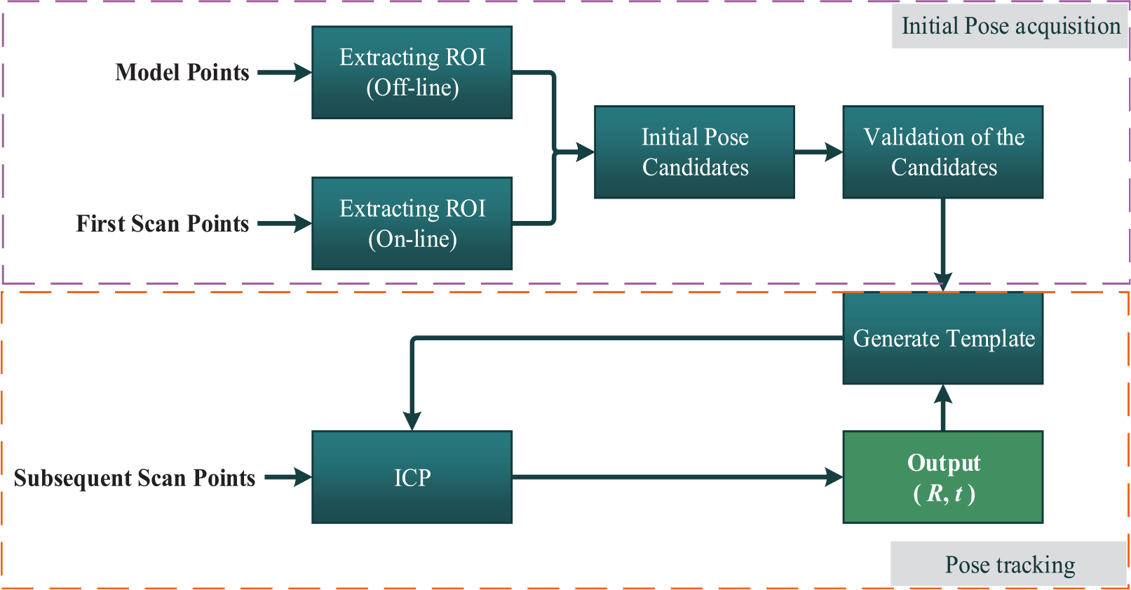
Pipeline of the proposed relative pose estimation method.
First, the coordinate system of the chaser spacecraft and the target spacecraft should be introduced as shown in Figure 2.

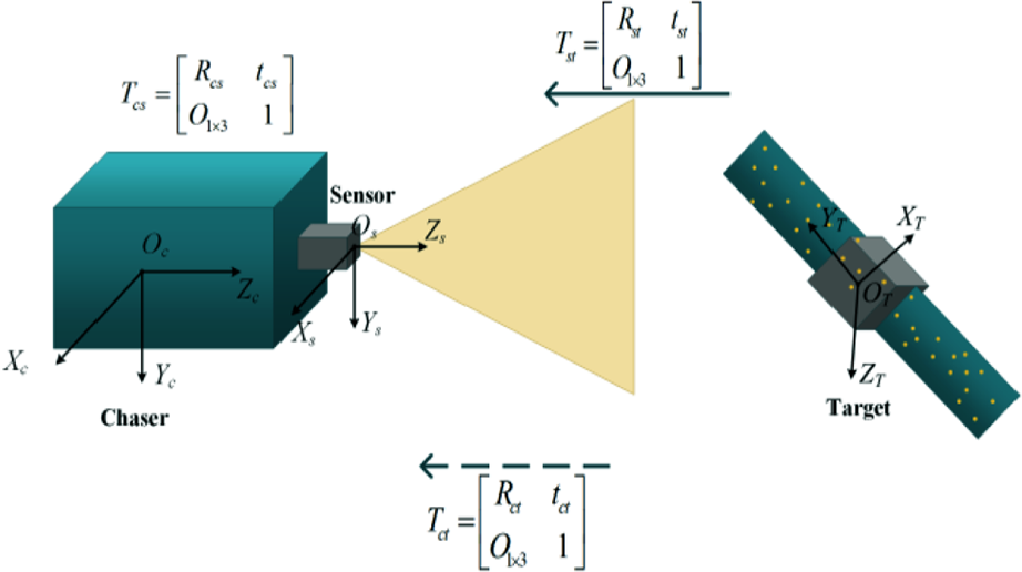
Coordinate systems.
ROI extracting
For most spacecrafts,
28
there are large-scale solar arrays compared to the body size as shown in Figure 3; the length of solar arrays is significantly larger than
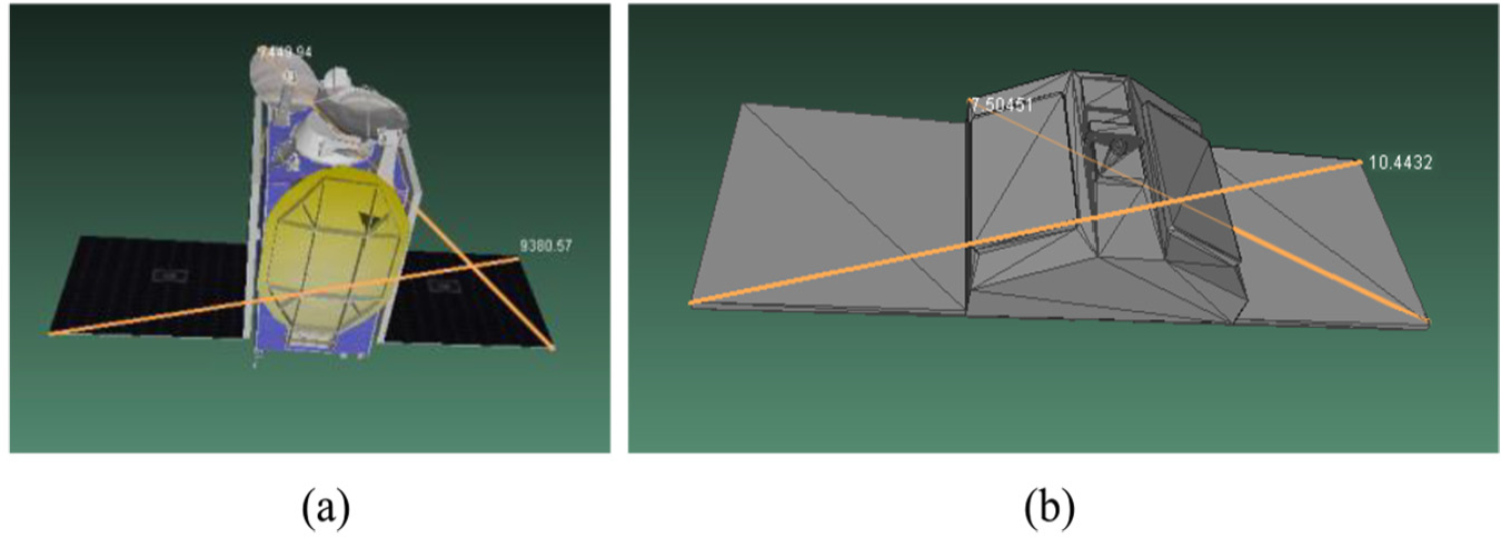
Satellite models: (a) a communication satellite and (b) cyclone global navigation satellite system.
Since the geometric model of the uncooperative spacecraft is known, the plane ROI can be directly determined based on the distance between the scanning points. The process of extracting the ROI is shown in Algorithm 1.
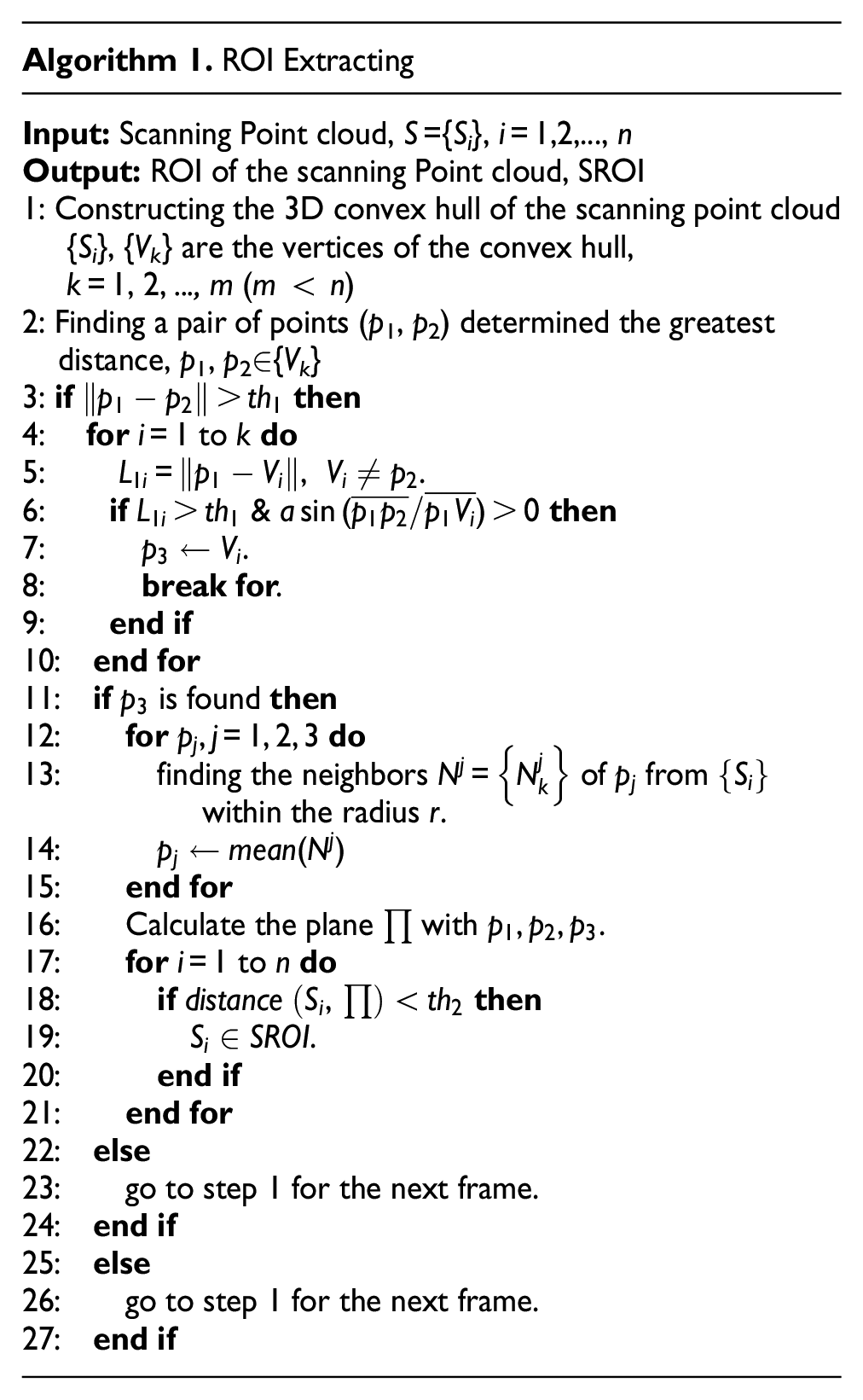
The plane parameters can be calculated by three non-collinear scanning points
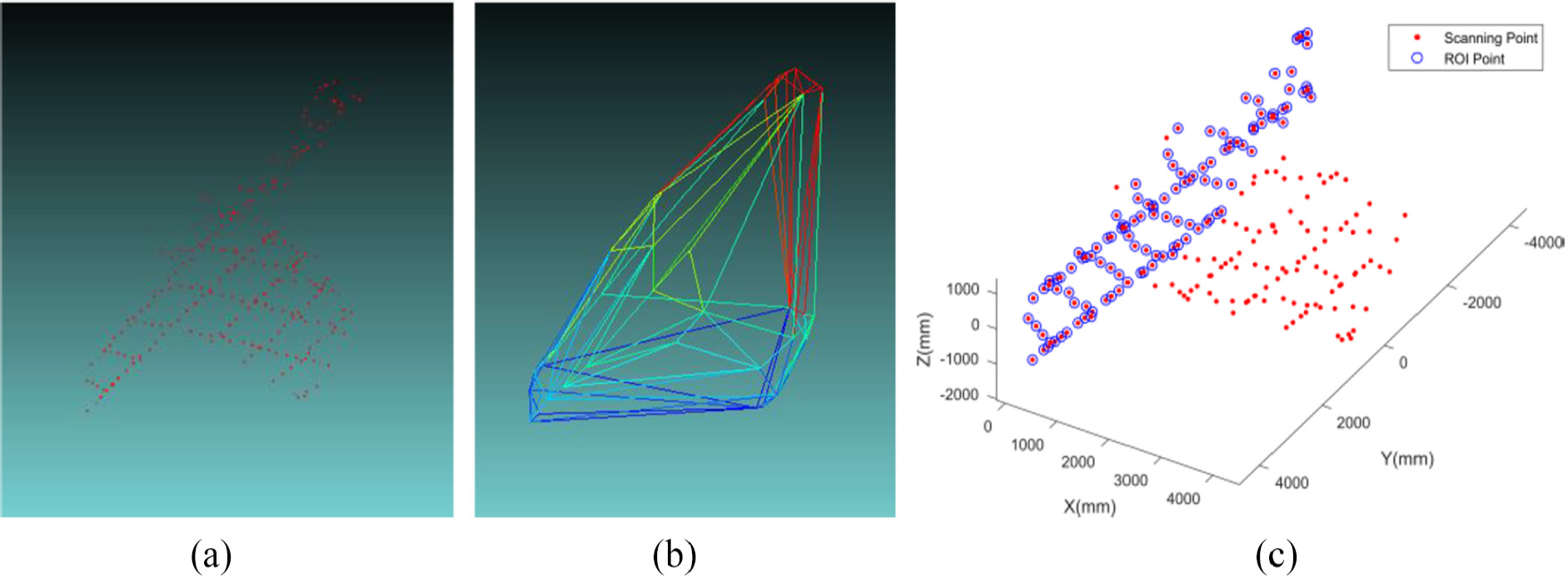
ROI extracting: (a) scanning point cloud, (b) 3D convex hull and (c) ROI of scanning point cloud.
Acquiring the initial pose
When the SROI is extracted, the initial pose can be acquired by the flow as shown in Figure 5.
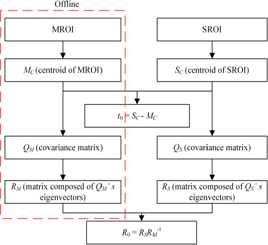
Flowchart of initial pose acquisition.
The PCA algorithm is used for acquiring the initial pose. The covariance matrix
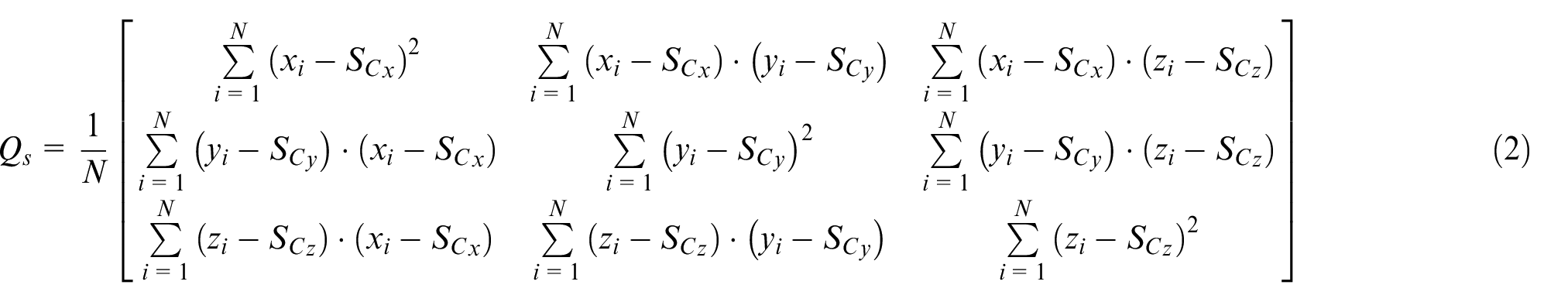

where

The matrix

The PCA allows estimation of the three main axes targets without ambiguity, but their directions remain undetermined. Thus, four possible solutions were generated. That is to say, there are four possibilities for
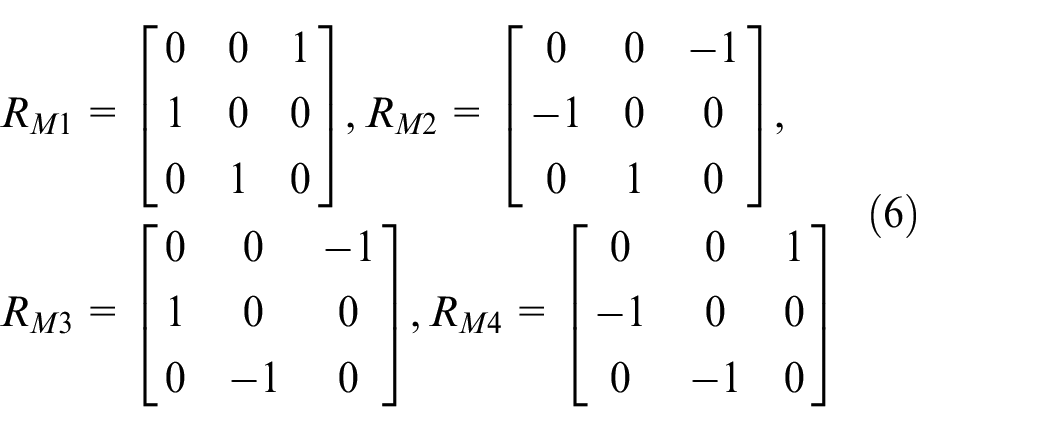
The four candidate rotation matrices

where
Pose tracking
The correctness of the initial pose estimation directly affects the effectiveness of the pose tracking. Therefore, the correctness of the initial pose should be judged before entering the pose tracking phase. And the procedure is described in Algorithm 2. The poses
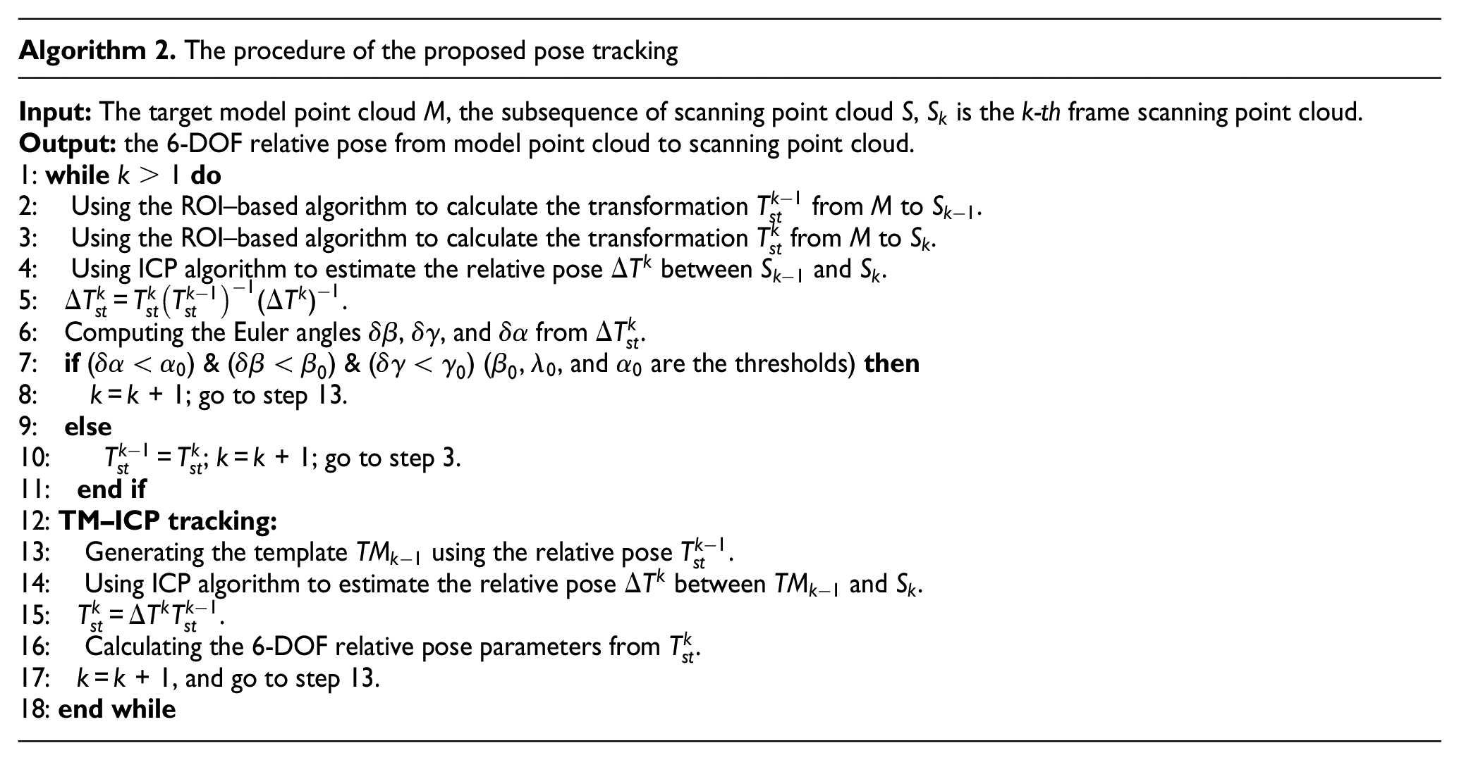
The general ICP-based pose tracking process is shown in Figure 6(a). However, due to the influence of the initial pose and the registration of the local point cloud and the overall model point cloud, the error will gradually increase during the tracking process (although the error will decrease later). Generally, the registration between adjacent frames is relatively accurate and stable, and is inspired by the TM algorithm which is used for initial pose acquisition; 16 an improved tracking strategy named TM-ICP is presented as shown in Figure 6(b). Different from the general ICP-based pose tracking process to register the scanning point cloud with the whole model point cloud, the ideal local point cloud (template) is generated by the pose of the last frame 14 and is used to register with the current scanning point cloud to obtain the pose. The template provides a local point cloud, which has a large overlap with the current scanning point cloud, and provides a truth pose, which can make the ICP have high precision and stability. Pseudo code of TM-ICP method is shown in Algorithm 2 (TM-ICP tracking).
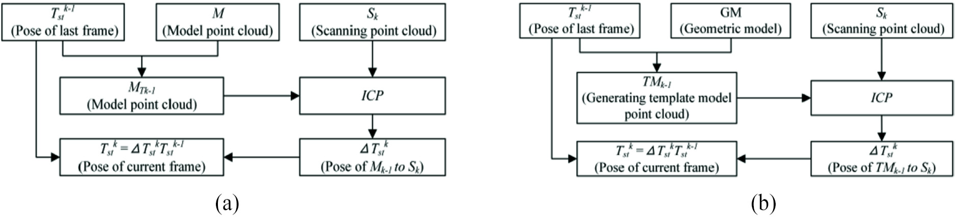
Flow diagram of pose tracking: (a) ICP algorithm and (b) TM-ICP algorithm.
Experiments
In this section, numerical simulation experiments and field experiments have been performed to test the performance of the proposed algorithm. Figure 7 shows the uncooperative target models used in the experiments and the Lissajous scan pattern used by the sensor, which generates sparse point cloud with an uneven density.
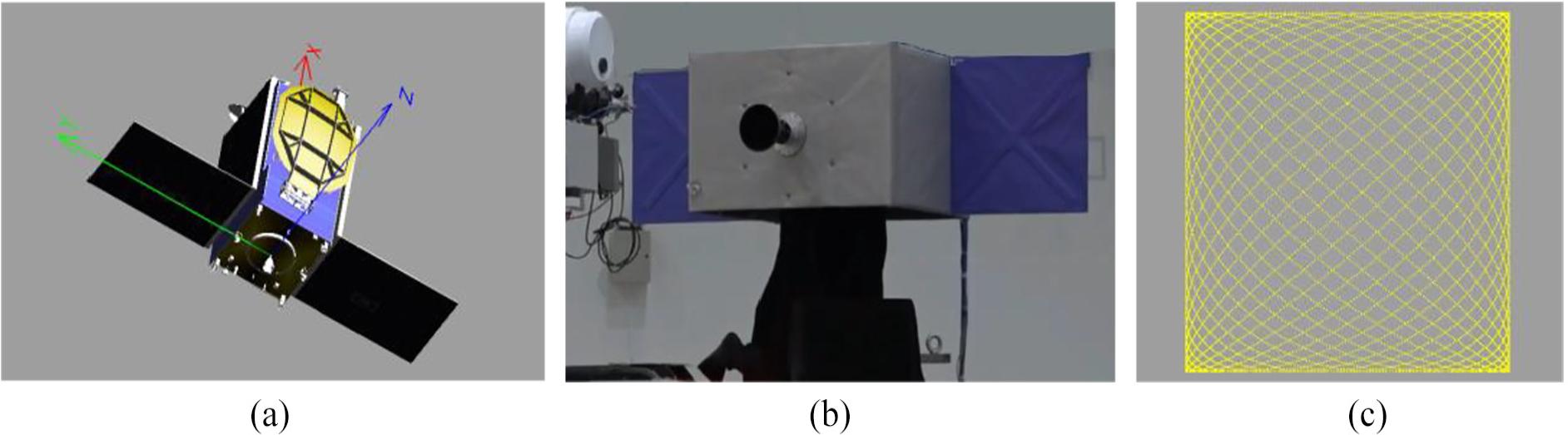
(a) Model in simulation experiments, (b) mock-up in field experiment and (c) Lissajous pattern.
The size of the simulation model (Figure 7(a)) is 1521 × 559 × 870 mm, and the size of the simplified mock-up (Figure 7(b)) is 2350 × 660 × 1016 mm.
A commercial desktop PC equipped with an Intel™ I5 CPU at 2.4 GHz is used to obtain the experimental results and the proposed algorithm is implemented in C++.
Simulation experiments
ROI-based algorithm test
It is difficult to quantify the performance of the ROI-based algorithm of large pose variations in laboratory tests; thus, a simulation environment which had been described in Yin et al., 15 including simulated sensor point clouds and providing the true relative pose between the uncooperative space target and the sensor, is used. The performance of the initial attitude estimation algorithm is tested in terms of both computational cost and pose estimation performance first, and then, the effectiveness of the pose tracking strategy is tested.
All the Euler angles in the experiments use the 231 convention and the ranges of variation of the Euler angles are [−180°, 180°], [−90°, 90°] and [−180°, 180°] (corresponding to β, γ and α).
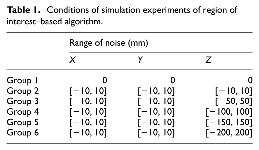
Since we cannot exhaust all the attitudes in the rotation space, we sample at intervals of 10° in each rotation region of the three rotation axes, which means that there are 26,011 sets of point cloud data in each group. And the number of scanning points is below 500. The anti-noise performance of the proposed method should be test too. Therefore, six groups’ simulation experiments were designed in different noise conditions as shown in Table 1. The noise range [a, b] represents the range of random noise along each axis direction.
Conditions of simulation experiments of region of interest–based algorithm.
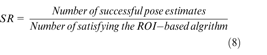
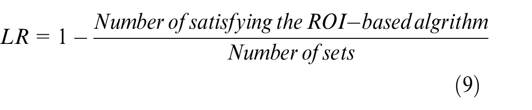
SR (Equation (8)) and loss rate (LR, Equation (9)) are defined to discriminate whether the algorithm is successful or not. A 5° angular error threshold is used to consider whether the result of pose estimation succeeds or not
The SR and LR in different noise are shown in Figure 8.
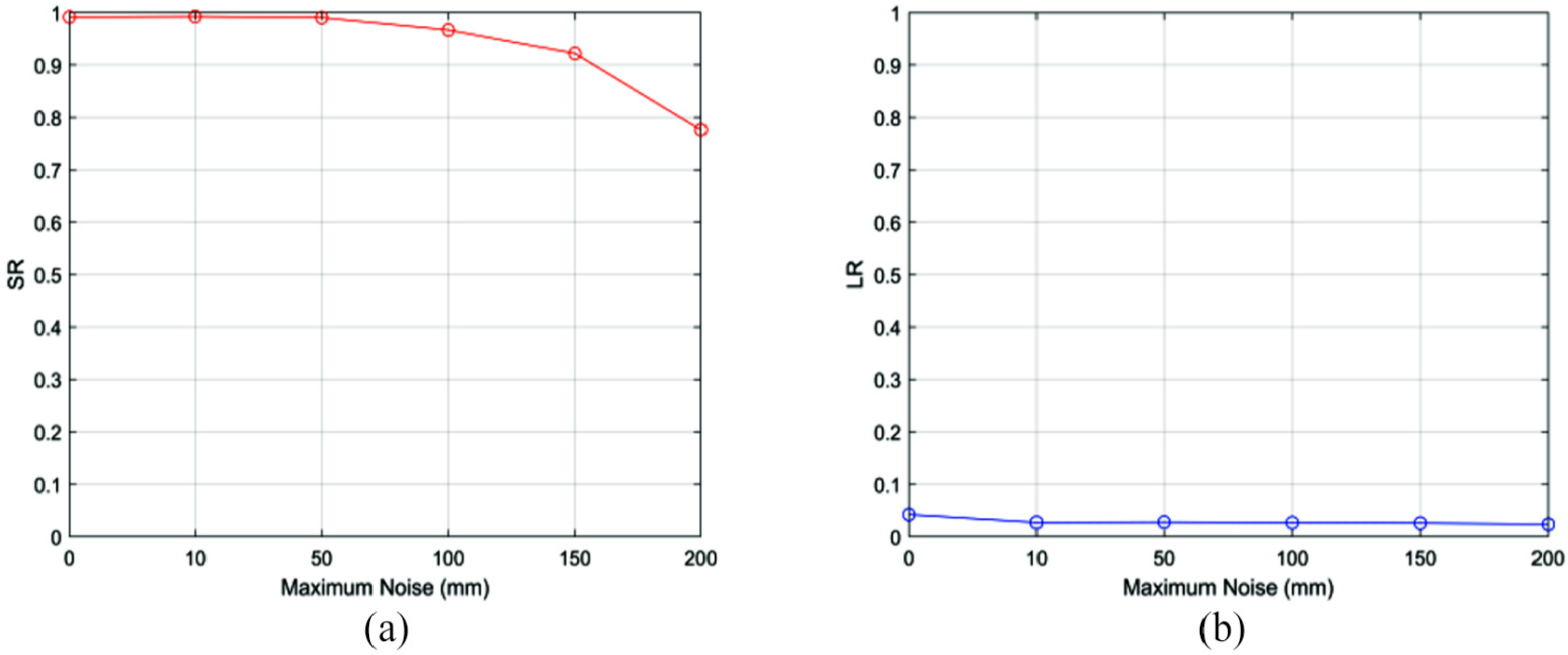
Effects of noise (a) on SR and (b) on LR.
From Figure 8, it can be seen that the proposed algorithm has a high SR, even with a maximum random noise of 150 mm. The SR is more than 90% and the LR is less than 3%. As the noise increases, the SR decreases slightly, but within the noise range tested here, SR and LR are high enough for pose acquisition.
The average values of the absolute estimation error are collected in Figure 9. In the maximum noise 200 mm tested in this paper, the position error is less than 200 mm and the attitude error is less than 4°. Although the position error and the attitude error increase as the noise increases, the accuracy is still high enough for pose acquisition.
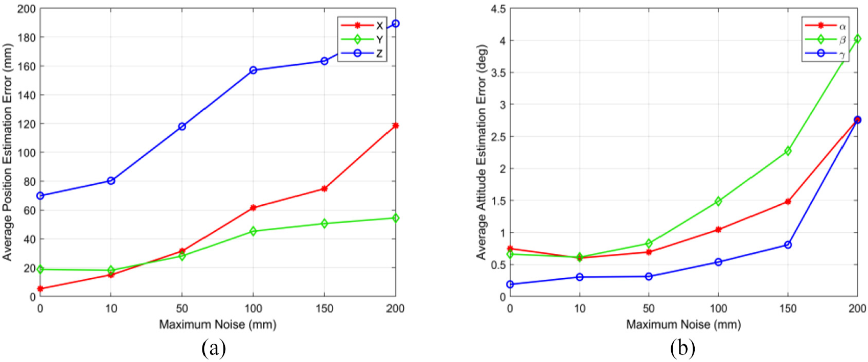
Average estimation error of initial pose: (a) position error and (b) attitude error.
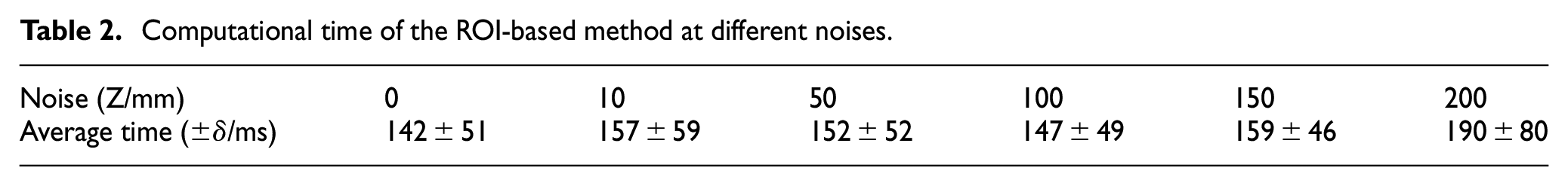
The computational time of the proposed algorithm is collected in Table 2. It can be seen that under different noises, there is no significant difference in computational time and the algorithm is faster than 5 Hz, which is fast enough for the pose tracking step of tumbling target with a high tumbling angular velocity.
Computational time of the ROI-based method at different noises.
Pose tracking test
As the spinning uncooperative spacecraft usually rotates around the maximum or minimum inertia axis, the two cases of rotating around the Y axis and Z axis (Figure 7(a)) were tested. And the TM-ICP algorithm and ICP algorithm for tracking are compared. Since the sampling frequency of LiDAR is generally higher, the distortion of the scanning point cloud is not considered in the rotation process of the target.
In test 1, the initial attitude (α, β, γ) is set as (85°, 0°, 90°). The target rotates around the Z axis of the model and is sampled at 5° interval. So the number of the simulated sensor point cloud data is 73. The Gaussian white noise with a standard deviation of 10 mm is added to X, Y and Z direction, and a Monte-Carlo simulation with 100 independent runs is performed.
The average rotation error and translation error of test 1 are given in Figures 10 and 11. The shading in the figures represents the boundary of the standard deviation of the error.
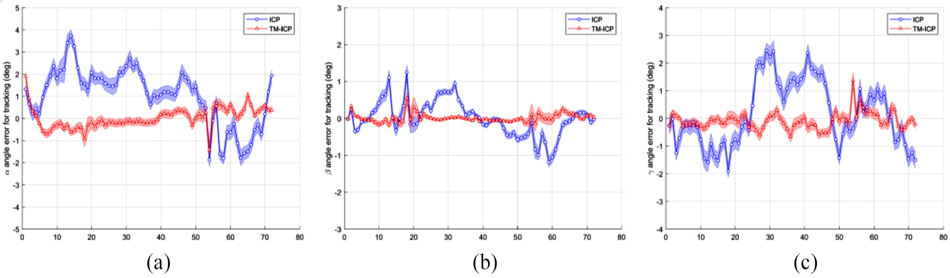
Angle error for tracking with the initial pose (85°, 0°, 90°): (a) α angle error, (b) β angle error and (c) γ angle error.
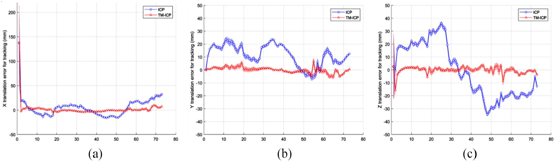
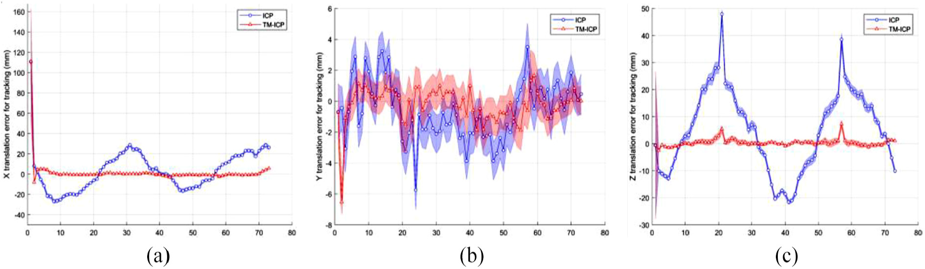
Translation error for tracking with the initial pose (85°, 0°, 90°): (a) X translation error, (b) Y translation error and (c) Z translation error.
From Figures 10 and 11, it can be found that the ROI-based algorithm can provide an accurate initial attitude and a good initial position, and the TM-ICP pose tracking method has higher accuracy and stability than ICP algorithm. The rotation error is less than 1° and the position error is less than 10 mm.
In test 2, the initial attitude (α, β, γ) is set as (0°, 80°, 10°). The target rotates around the Y axis of the model and is sampled at 5° interval. So the number of the simulated sensor point cloud data is 73. The Gaussian white noise with a standard deviation of 10 mm is added to X, Y and Z direction, and a Monte-Carlo simulation with 100 independent runs is performed. The rotation error and translation error of test 2 are given in Figures 12 and 13. The shading in the figures represents the boundary of the standard deviation of the error.
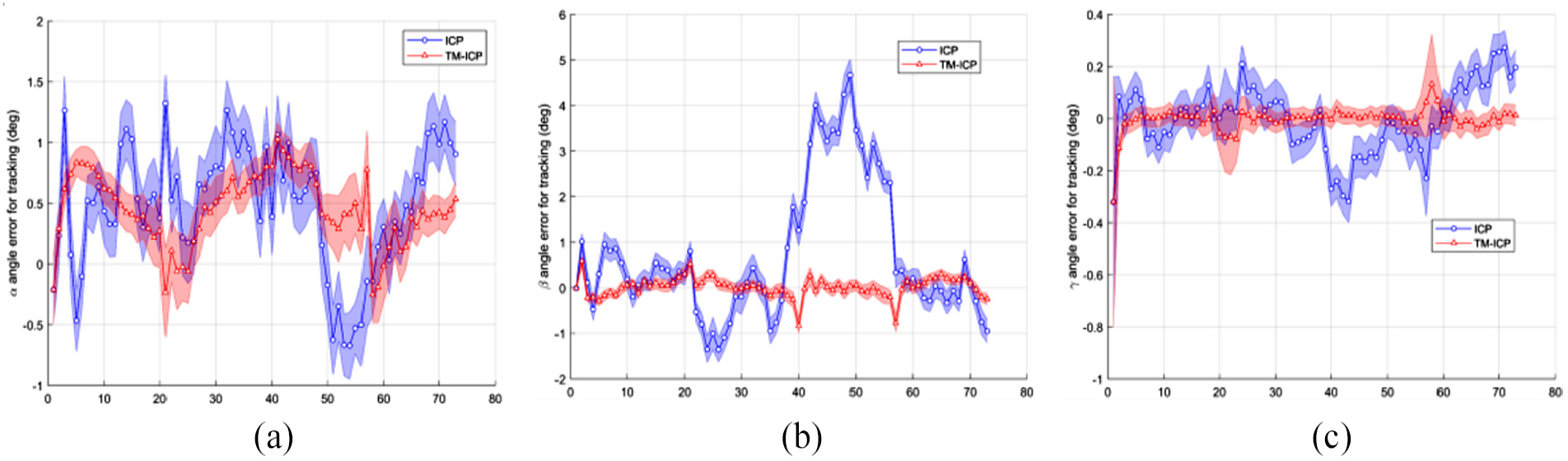
Angle error for tracking with the initial pose (0°, 80°, 10°): (a) α angle error, (b) β angle error and (c) γ angle error.
Translation error for tracking with the initial pose (0°, 80°, 10°): (a) X translation error, (b) Y translation error and (c) Z translation error.
From Figures 12 and 13, it can be seen that the ROI-based algorithm can still provide an accurate initial attitude and a good initial position, and the TM-ICP pose tracking method has higher accuracy and stability than ICP algorithm. When the target rotates with its maximum inertia axis, it has the approximate precision and stability when rotating around the minimum inertia axis.
Field experiments
The field experiment system shown in Figure 14 consists of a simplified mock-up which is mounted on a three-axis turntable with a precision of 0.01°, a single-line scanning 3D-LiDAR system which is developed by BICE and installed on the manipulator arm, and a air-bearing guideway which floats on a near-perfectly flat floor, providing translation motion and rotation.
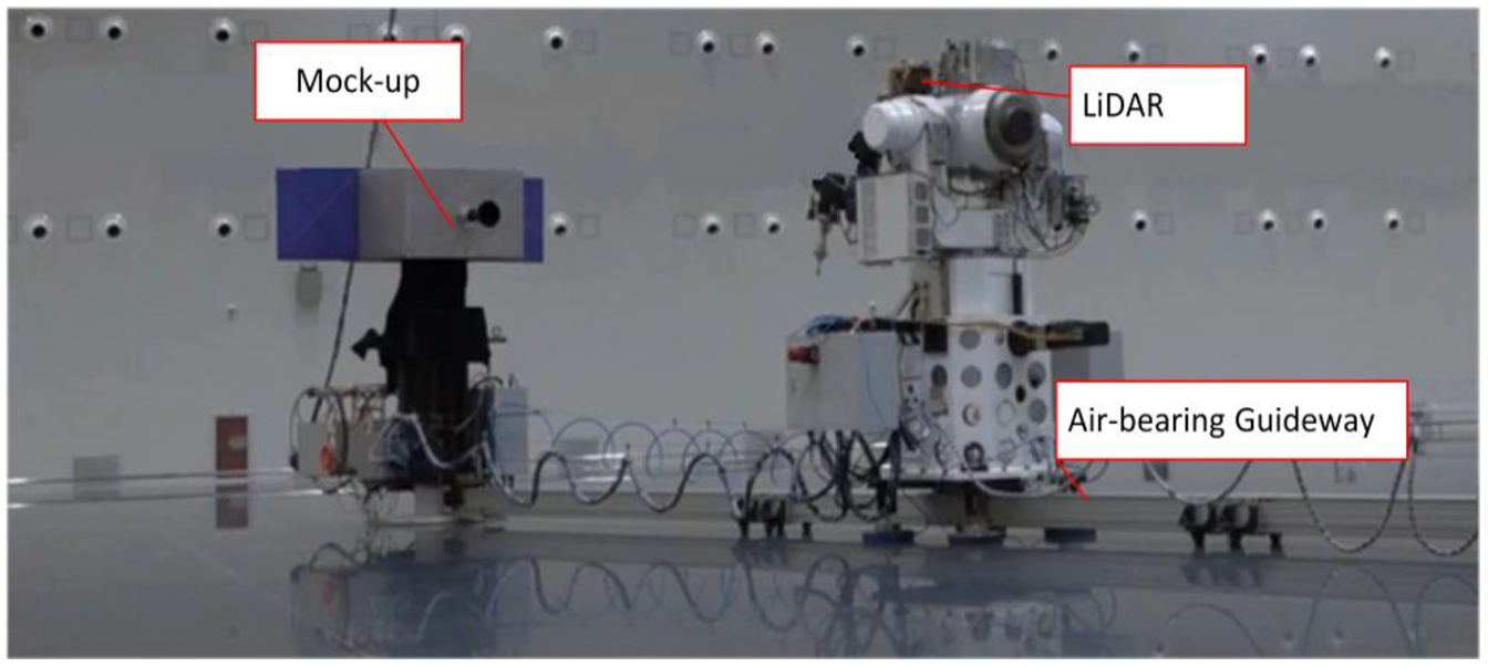
Field experiment.
The target is still, and the LiDAR rotates around the target with the air-bearing guideway at a distance of 7 m from the target, and rotation speed is 2°/s. The frequency of point cloud data acquisition is set to 1 Hz, and the experimental results are shown in Figures 15 and 16.
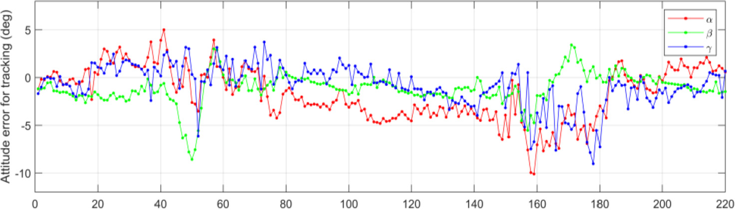
Attitude error of field experiment.
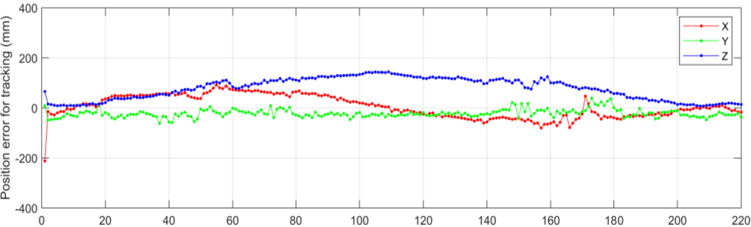
Position error of field experiment.
From the Figures 15 and 16, it can be found that ROI-based method can provide the accurate enough initial pose for the next pose tracking step. In the pose tracking step, the absolute error of the attitudes is about 5° and the absolute error of position is less than 150 mm. In addition, it should be noted that, around frame 50 and frame 159, the angle
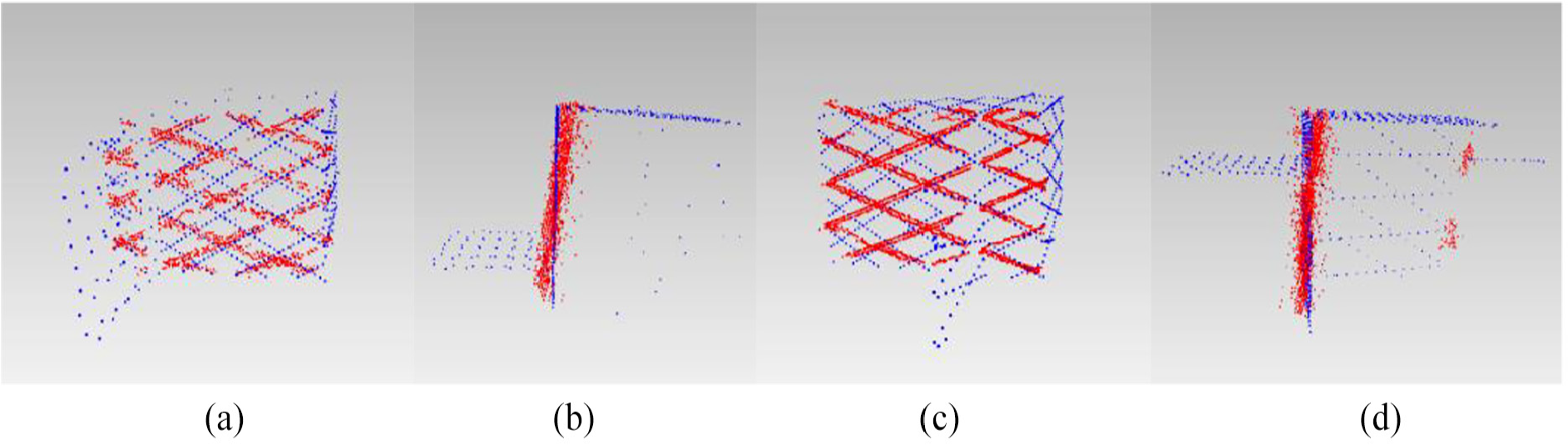
Scanning point cloud (red) and the corresponding templates (blue): (a) frame 50 (view 1), (b) frame 50 (view 2),(c) frame 159 (view 1), and (d) frame 159 (view 2).
Conclusion
The presented ROI-based method in this paper is both efficient, executing in less 0.2 s, and reliable, succeeding in over 90% of the almost entire space domain. And it is not limited by the type of sensors to obtain the 3D point cloud, such as scanning LiDAR, flash LiDAR or other stereo vision. For the dense point cloud, it is only used to down sample before ROI is extracted to ensure the real-time performance of the proposed algorithm. In addition, the TM-ICP method is proposed to achieve more accurate and more stable pose tracking. The results of the simulation experiments and field experiment also confirmed the effectiveness of the proposed method both in accuracy and stability.
The ROI-based method proposed in this paper is applicable to the uncooperative targets which have large-scale solar arrays (rectangle) compared to the body size. In future work, other methods of extracting regions of interest of different shapes may be considered.
Footnotes
Declaration of conflicting interests
The author(s) declared no potential conflicts of interest with respect to the research, authorship, and/or publication of this article.
Funding
The author(s) disclosed receipt of the following financial support for the research, authorship and/or publication of this article: This research was funded by the National Key R&D Program of China under grant 2017YFB1302503 and the National Natural Science Foundation of China under grant 61633002.