
Abstract
For the factors of complex image background, unobvious end-effector characteristics and uneven illumination in the pose detection of parallel robot based on binocular vision, the detection speed, and accuracy cannot meet the requirement of the closed-loop control. So a pose detection method based on improved RANSAC algorithm is presented. First, considering that the image of parallel robot is rigid and has multiple corner points, the Harris–Scale Invariant Feature Transform algorithm is adopted to realize image prematching. The feature points are extracted by Harris and matched by Scale Invariant Feature Transform to realize good accuracy and real-time performance. Second, for the mismatching from prematching, an improved RANSAC algorithm is proposed to refine the prematching results. This improved algorithm can overcome the disadvantages of mismatching and time-consuming of the conventional RANSAC algorithm by selecting feature points in separated grids of the images and predetecting to validate provisional model. The improved RANSAC algorithm was applied to a self-developed novel 3-degrees of freedom parallel robot to verify the validity. The experiment results show that, compared with the conventional algorithm, the average matching time decreases by 63.45%, the average matching accuracy increases by 15.66%, the average deviations of pose detection in Y direction, Z direction, and roll angle
Introduction
Parallel robot has received wide attention in recent years for the advantages of strong rigidity, powerful carrying capacity, stable structure, high precision and low movement inertia, and so on. 1 The pose of end-effector is an important parameter reflecting the kinematic state in control research of parallel robot. Accurate pose detection can effectively reduce the error from kinematic model resolving and realize high-performance closed-loop control of parallel robot. However, the pose detection of end-effector for parallel robot is still difficult for the factors of the expensive detection equipment, the complex detection method, and the limited detection range.2,3 Currently, the detection methods mainly include appending measuring robot, locating by dual-frequency interferometer, multisensors, and machine vision.4–6 Compared with other methods, machine vision has the advantages of noncontact, powerful adaptability, high cost performance, and so on. 7 It is suitable to solve the problems of pose detection of parallel robot, which features the multi-DOF (degrees of freedom) movement, the complex movement trajectory and the difficulty of direct detection.
According to the number of cameras, the visual pose detection method can be classified into monocular vision, binocular vision, and multivision. Compared with monocular vision, binocular vision has no strict requirements for the geometric constraints among the markers, which significantly reduces the designing requirements of markers. Besides, binocular vision can be used for data fusion, which can improve the detection accuracy and robustness. 8 Though multivision has higher detection accuracy, it needs multiple images to match, which leads to the increasing matching difficulty and time. So binocular vision has been widely used. However, for the binocular vision applied to the pose detection for realizing closed-loop control of parallel robot, it is difficult to place landmark on the end-effector. In addition, for the factors of complex image background, unobvious end-effector characteristics, and uneven illumination, it is difficult to achieve the space matching accurately and rapidly. And the detection speed and accuracy cannot meet the requirement of the closed-loop control.9,10 Therefore, this paper improves the matching algorithm in pose detection without landmark on end-effector and focuses on increasing the speed and accuracy of pose detection of parallel robot by improving and optimizing the binocular vision algorithm. Furthermore, the improved method is applied to a self-developed novel 3-DOF parallel robot to verify the validity. It lays the foundation for the real-time high-performance closed-loop control of parallel robot.
The pose detection process based on binocular vision includes the images acquisition, the feature point extraction, the stereo matching, the camera calibration, and the pose estimation. Among all the processes, stereo matching is the most important. The speed and accuracy of stereo matching determine the speed and accuracy of pose detection directly. 11 It is difficult to realize matching accurately and rapidly in the pose detection of parallel robot due to the external influences, such as the indoor lighting change, the uneven illumination, and the noise. Thus, it is necessary to study the matching methods. The matching methods mainly include the gray-based matching 12 and the feature-based matching. 13 The former calculates the minimization of error sum of squares of all the image pixels to obtain transformation parameters among images with iterative computation. It could increase the amount of computation, slow down the computing speed and lead to poor robustness. While the feature-based matching algorithm can extract image feature points stably and realize image matching using gray information to derive symbol feature, which can improve calculating speed and robustness. Compared with the marker-free method, the marker method is simple and efficient in the feature-based matching. However, the markers are easily confused and obscured.14,15 In addition, because of the multi-DOF movement, the complex movement trajectory, and the small end-effector, it is difficult to find a suitable position to attach marker in parallel robot. So in this paper, the pose detection of parallel robot is realized using marker-free method. 16
As a milestone of feature matching, the matching method of Scale Invariant Feature Transform (SIFT) is proposed by Lowe 17 based on 2D image scale–space theory. In order to detect the stable feature points efficiently, Lowe 18 optimized LoG spot detection method by adopting the differential Gauss extreme DoG operator as the detection function. The SIFT algorithm based on DoG operator can not only deal with the matching problem in the conditions of translation, rotation, and scale transformation among images, but also remain comparatively stable ability of feature matching.19,20 Based on the above advantages, the SIFT algorithm has been widely used on the occasions of the static image registration, the panoramic image mosaic, the face recognition, and others, which do not require good real-time performance.21,22 However, for matching with high-speed requirement in pose detection of parallel robot, the conventional SIFT algorithm is complex and needs more time to match. 23 The Harris corner detection algorithm is easy and stable. It is not susceptible to light and rigid geometric distortion, but it is sensitive to noise, and it has got the scale invariance. 24 Therefore, some scholars have put forward the matching algorithm by combining Harris with SIFT. For example, a Harris–SIFT algorithm is proposed and validated in matching of binocular vision in Zhao et al. 25 by combining Harris significance with SIFT descriptor. This method effectively improves the real-time performance of matching algorithm, but the information of corner points detected by Harris is less than the information of feature points detected by SIFT. The Harris–SIFT algorithm also has the problem of mismatching. 26
Compared with other refining methods of image matching, the RANSAC algorithm can estimate high-precision parameters from the data set containing a large number of outliers, which are seriously deviated from normal range and unable to accord with the mathematical model. It has been widely applied in vision detection due to the stronger robustness.27,28 However, the accuracy of the RANSAC algorithm depends on the iterative number. More iterations may need more time. Generally, the loss function is modified to improve the RANSAC algorithm. 29 For example, the joint probability distribution of the inlier, which may be described by model and the outlier error are used to verify the model. It can improve the accuracy of model estimation. 30 For the factors of complex image background, unobvious end-effector characteristics and uneven illumination in the pose detection of parallel robot based on binocular vision, the distribution of points in matching data set is uneven, and the data set contains many outliers. So it is difficult to realize high-accuracy pose detection of parallel robot using the conventional RANSAC algorithm and improved RANSAC algorithm based on modified loss function.
For the above problems, the binocular vision is used in pose detection of parallel robot in this paper. The matching problem of pose detection is studied in priority. In order to solve the problem of poor real-time performance of matching, the Harris–SIFT algorithm is adopted to realize image prematching considering that the images of parallel robot without landmark on end-effector are rigid images and have multiple corner points in this paper. For the problems of mismatching in Harris–SIFT algorithm, an improved RANSAC algorithm is proposed to refine the prematching results. The improved algorithm can remove the mismatching points in Harris–SIFT algorithm by selecting feature points in separated grids of the images and predetecting to validate provisional model. The improved algorithm can improve real-time performance and accuracy of image matching simultaneously. As a result, the method improves the accuracy of pose detection of parallel robot and provides a feasible solution for the real-time high-performance closed-loop control of parallel robot.
RANSAC algorithm and improvement
RANSAC algorithm
The data set after prematching contains the inliers and the outliers. The outlier is produced by the error detection, calculation, or assumption. The RANSAC algorithm is a robust model parameter estimation algorithm. It calculates the mathematical model parameters and tests the model using the remaining points to get effective data samples. As a result, the efficiency of image processing is improved using fewer points to estimate model parameters. It makes up for the deficiency of general parameter estimation method using all points.
According to the basic idea of RANSAC algorithm, the target transformation model H between two images needs to be calculated by Sampson distance. Then, the matching points are tested by the target model. The mismatching points are removed at last. The selection of target model and the representation of Sampson distance are as following:
1. Calculating the target model H between two images: The eight matching point pairs are randomly selected to calculate the provisional candidate model F usually in RANSAC algorithm. The Sampson distance d of the matching point pairs corresponding to the model F is calculated. The threshold value k is set. The points, which meet the condition of d < k are selected as inliers. Furthermore, the model F, which includes most inliers, is optimized to obtain the target model H. Finally, the matching points are re-estimated by target candidate model H. The mismatching point pairs are removed. Projection transformation model is expressed as follows
where (x, y, 1) and (x’, y’, 1) represent the homogeneous coordinates of matching point pairs m(x, y) and m (x’, y’), respectively.
2. The representation of Sampson distance d: for any matching point pair m(x, y) and m(x’, y’), the representation of Sampson distance d in candidate model F can be calculated using Equation (2)
The improvement of RANSAC algorithm
The conventional RANSAC algorithm is capable of interpreting and smoothing data containing gross errors. However, for the factors of complex image background, unobvious end-effector characteristics and uneven illumination in the pose detection of parallel robot based on binocular vision, it is difficult to detect the pose based on the conventional RANSAC algorithm accurately and rapidly. It has the following problems:
The two candidate points could be considered to be one point if the distance between the two points is too close when selecting a sample randomly. It will lead to low-accuracy of the fundamental matrix.
Because the prematching data set of the parallel robot images includes outliers, it is necessary to look for the support set of candidate models every time when selecting sample set randomly. Too much time is needed to look for the support set when there are many errors in observation data set.
So, an improved RANSAC algorithm is proposed by selecting feature points in separated grids of the images and predetecting to validate provisional model. First, for the problem (a) mentioned above, instead of random sampling, the sampling method selecting feature points in separated grids is proposed. The image is divided into blocks and the blocks without matching points are removed. For increasing the sparsity of the sample distribution and preparing for validating provisional model by predetecting, the samples are selected randomly from different blocks to constitute a random sample set with sparse distribution. Second, for the problem (b) mentioned above, the provisional model is validated by predetecting. The validating point is selected randomly from sample set to validate the provisional model. It can remove the invalid model in advance to avoid useless calculation in a large number of support set.
These improvements not only make the model parameters more accurate, but also overcome the deficiency of conventional RANSAC algorithm, which has to detect all the observed data points after determining the provisional model parameters. The improved algorithm reduces the amount of computation and improves the detection efficiency. Thus, for the original matching point pairs, the improved RANSAC algorithm is as follows:
Selecting feature points in separated grids. i. The image is divided into ii. The eight matching point pairs are randomly selected from sample set S to obtain provisional candidate model F.
Validating provisional model by predetecting.
The ninth point is validated whether it is the support set of candidate model F: if it is yes, this provisional candidate model F is a candidate model F. Otherwise, the nine matching point pairs are reselected and process 1 is repeated.
Detecting all matching point pairs by candidate model F and the threshold k to get m, which is the number of the support set for candidate model.
If
Optimizing target model F and determining the target model H ultimately.
The counter plus 1 when random sample set is selected every time. If the model parameters are not found after repeating k times, the program is terminated.
Pose detection of parallel robot
The improved RANSAC algorithm is applied to pose detection of a self-developed novel 3-DOF parallel robot to verify the validity. The prototype of parallel robot is shown in Figure 1. The robot is mainly composed of the platform, connecting rods, columns, and sliders. The moving platform is connected to the fixed platform by three limbs. Each body of the column guide is equipped with slider. Pose of end-effector is changed by the motor driving slider. The parallel robot can realize 2D movement and 1D rotation. The capacity of rotation can reach 115°. It breaks through the limit of the rotation capacity in conventional parallel robot.
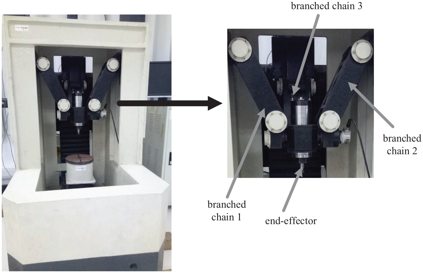
Prototype of the novel 3-DOF parallel robot.
For the pose detection of the novel 3-DOF parallel robot, images are acquired by left and right cameras, and feature points are extracted based on Harris operator first. Second, feature points are prematched by Harris–SIFT algorithm to improve the matching speed. Third, an improved RANSAC algorithm is proposed to solve the mismatching problem. Finally, the matching points after refining are taken into the binocular vision coordinate model to get the pose of parallel robot.
Image acquisition and feature point extraction
Image acquisition
This paper depends on the system of MICROVISION binocular stereovision as a development platform. Camera model is MV-1300FM. The cameras are installed in front of parallel robot. The height from ground and the angle between cameras can be adjusted flexibly. The original images of parallel robot are acquired by left and right cameras at the same time, which are shown in Figure 2. The original image size is 1280 × 1024 and the format is bmp.
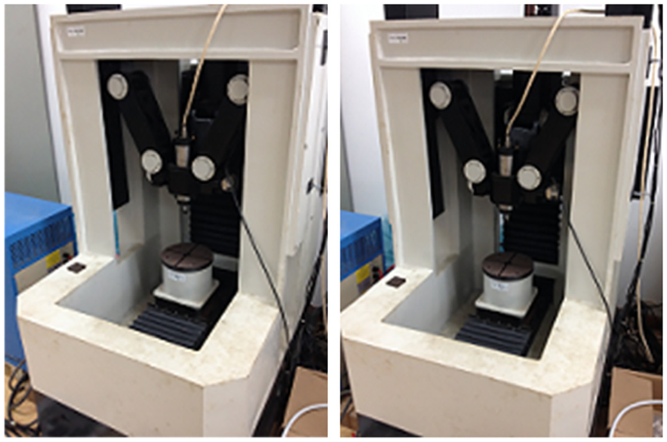
Original images of the parallel robot.
Feature point extraction based on Harris
Because parallel robot has obvious rigid-body characteristics, we extract the feature points in images using the Harris. It has high re-examination rate in terms of rigid geometric distortion and brightness changes, and it is simple and stable. 30 In feature point extraction based on Harris, the second-order matrix of pixels is expressed as follows
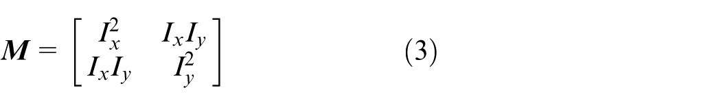
In the formula,

The det
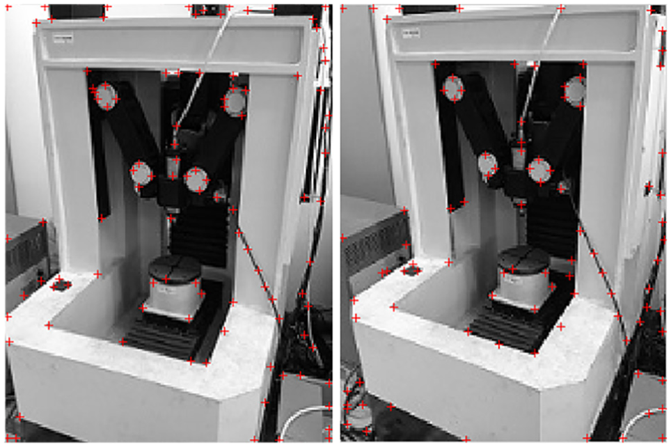
Extracted feature points using Harris.
Stereo matching and three-dimensional coordinate calculation of mark points
Stereo prematching based on Harris–SIFT algorithm
Feature detection based on Harris is deemed to be stable, but sensitive to noise. It even cannot achieve scale invariance. In order to solve these problems, we combine Harris with SIFT to achieve the prematching of robot images. The feature points are extracted by Harris and matched by SIFT, thereby the feature points have common feature of the two algorithms that can improve real-time performance and accuracy. 27
Application of improved RANSAC algorithm
The improved RANSAC algorithm is applied to the stereo matching to refine prematching result. So the real-time performance and accuracy of matching can be improved. The matching point pairs refined by conventional RANSAC algorithm and improved RANSAC algorithm from prematching results of Harris–SIFT algorithm are shown in Figure 4. Compared with the conventional RANSAC algorithm (Figure 4(a)), the matching result of improved RANSAC algorithm (Figure 4(b)) contains fewer mismatching point pairs, and the matching accuracy can be improved.
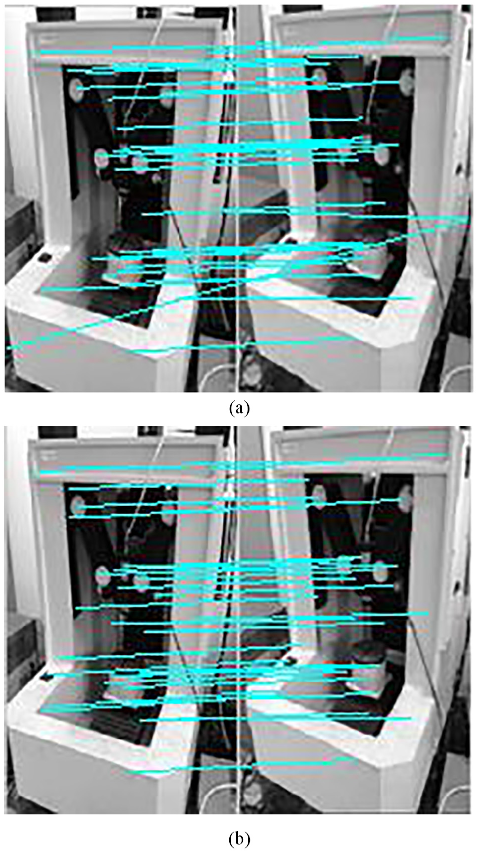
Matching point pairs refined by conventional RANSAC algorithm and improved RANSAC algorithm from prematching results of Harris–SIFT algorithm. (a) Matching point pairs refined by conventional RANSAC algorithm. (b) Matching point pairs refined by improved RANSAC algorithm.
Camera model
In order to calculate the actual three-dimensional coordinates of spatial points according to the image coordinates of matching point pairs, the pinhole model is used to analyze the camera imaging model, as shown in Figure 5. According to the camera calibration method of Zhang,
31
four coordinate systems are defined: (1) The world coordinate system
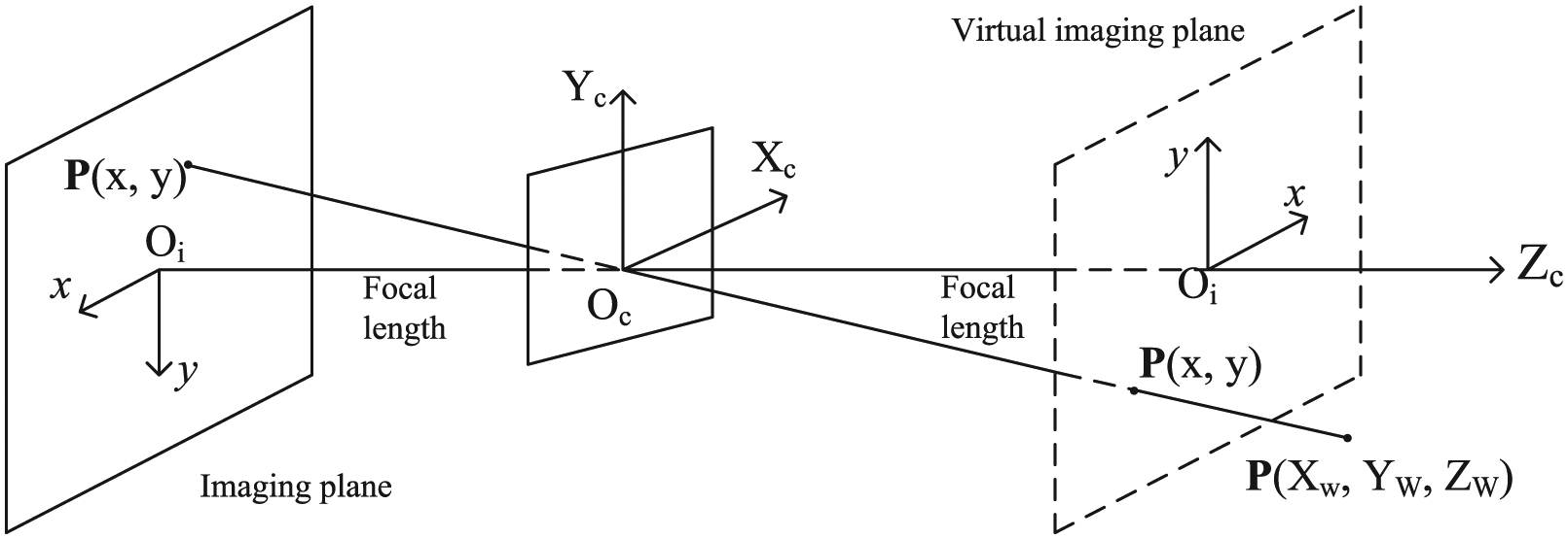
Pinhole imaging model.
According to pinhole imaging model, the any point

where ZC is the distance from focus to the image plane,
1. For spatial point M and projective point m, the transformation between
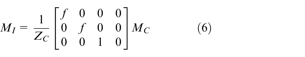
where ZC is the distance from focus to image plane,
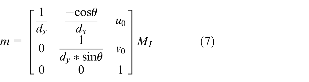
where
According to Equations (6) and (7), the transformation between
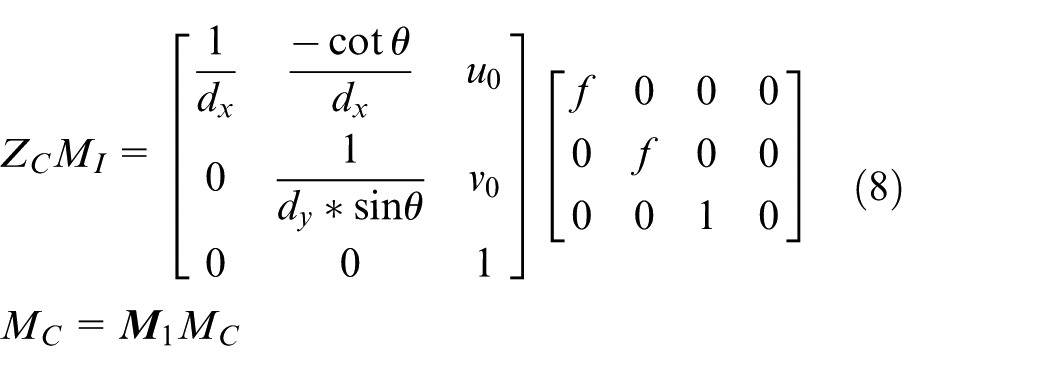
where
2. The transformation between
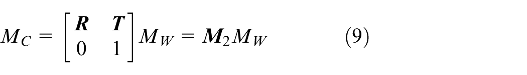
where
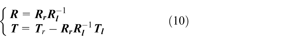
For binocular vision model, the internal and external parameters of left and right cameras can be obtained by camera calibration. Assuming that
Coordinate calculation of mark point
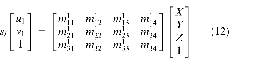
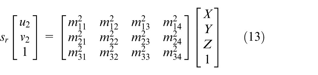
The coordinate of projective point imaged by the left and right cameras from the same spatial mark point of the end-effector of parallel robot can be acquired by matching. The spatial mark point
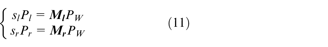
where
where
Parameter solution of parallel robot
Parallel robot coordinate system
According to the characteristics of robot, the parallel robot coordinate system is defined as Figure 6. The
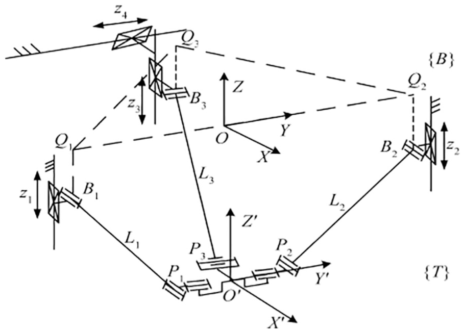
Coordinate systems of the novel 3-DOF parallel robot.
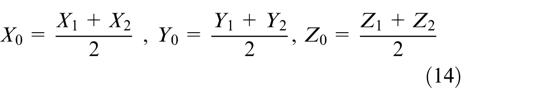
Position parameter calculation
In Figure 6, points
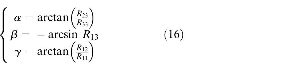
Pose parameter calculation
For the moving platform coordinate
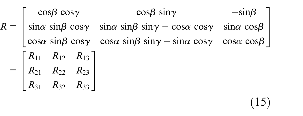
Then, the pitch angle
The parallel robot can do movement with three DOF. So the translation in
Experiment and analysis
Experimental platforms are as follows: (1) Hardware platform: The operating system is Microsoft Windows 7. The processor is Intel(R) Core(TM)2 Duo. The frequency is 2.66 GHz. The memory is 2 GB. The high-speed digital image acquisition cards are MV-1394A and MV1394B. The camera model is MV-1300FM. The lens model is AFT-0814MP. The calibration target model is AFT-CT430. (2) Software platform: The CCAS MICROVISION binocular stereovision development platform is used. It uses visual C++6.0 integrated development tools to prepare the human–computer interaction interface. The API function interface of each module is implemented by combining C++programming language with third-party software MATLAB.
Test method
In order to verify the advantages of improved RANSAC compared with conventional RANSAC algorithm in accuracy and speed, three-group experiments of pose detection are carried out. First, three-group images of parallel robot are acquired from different directions in three-group experiments, respectively. The improved RANSAC and conventional RANSAC algorithm are used for each group of images to refine the prematching results of Harris–SIFT algorithm. Then, these two methods are compared in the accuracy and time for each group. Finally, the extracted mark points are taken into the camera model to calculate the pose parameters. Then the acquired pose parameters are compared with actual pose parameters, which are obtained by laser distance measuring instrument of INR-Laser Scanner H and electronic Honeywell-HMR3100 to verify the validity of the pose detection method.
Result and analysis
The matching results of three-group images are shown in Figures 7–9 and Tables 1–3. In Figures 7–9, the left half of each image represents the images acquired by left camera, and the right half of each image represents the images acquired by right camera. Figures 7(a)–9(a) and Figures 7(b)–9(b) are the results of refining by conventional RANSAC and improved RANSAC algorithm, respectively. Figures 7(c)–9(c) is the mismatching point pairs in the prematching results of Harris–SIFT algorithm. It shows that the prematching results of Harris–SIFT algorithm in the three-group experiments contain many mismatching point pairs (Figures 7(c)–9(c)). Compared with the conventional RANSAC algorithm (Figures 7(a)–9(a)), the matching results of improved RANSAC algorithm (Figures 7(b)–9(b)) contain fewer mismatching point pairs, and the matching accuracy can be improved. The detailed data of the three-group experiments are shown in Tables 1–3. The MA can be calculated by Equation (17)
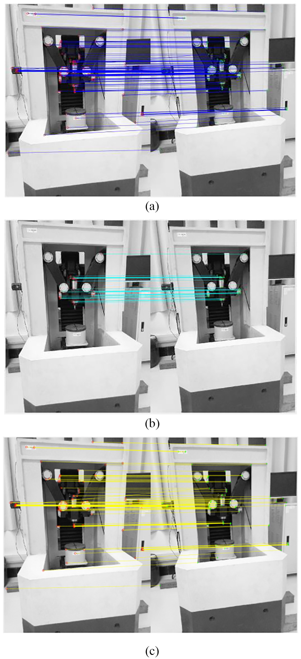
Matching results of the images acquired by the left-oriented cameras. (a) Matching results refined by conventional RANSAC algorithm from prematching results of Harris–SIFT algorithm. (b) Matching results refined by improved RANSAC algorithm from prematching results of Harris–SIFT algorithm. (c) Mismatching point pairs in the prematching results of Harris–SIFT algorithm.
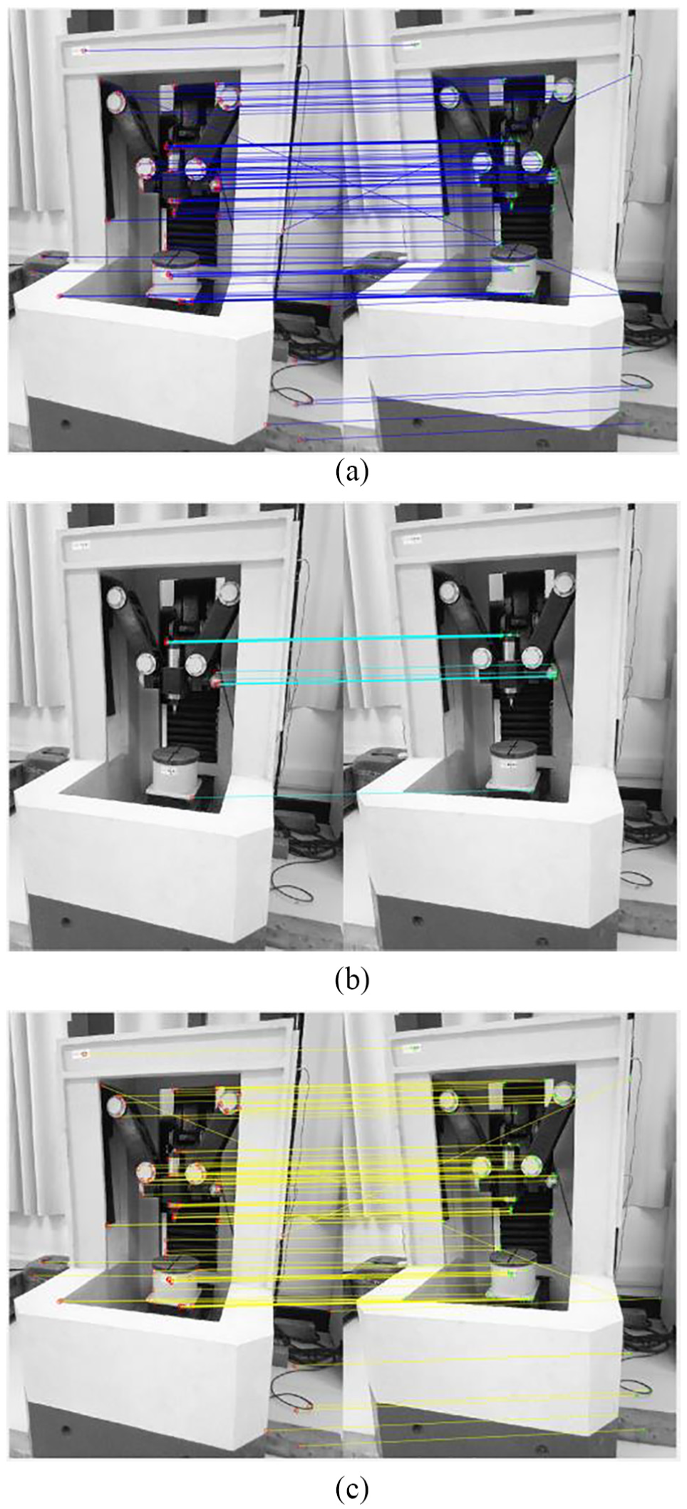
Matching results of the images acquired by the right-oriented cameras. (a) Matching results refined by conventional RANSAC algorithm from prematching results of Harris–SIFT algorithm. (b) Matching results refined by improved RANSAC algorithm from prematching results of Harris–SIFT algorithm. (c) Mismatching point pairs in the prematching results of Harris–SIFT algorithm.
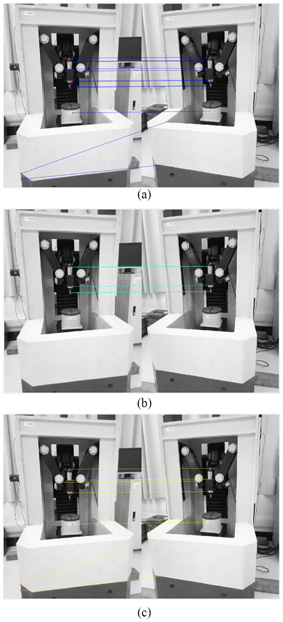
Matching results of the images acquired by the left-oriented camera and the right-oriented camera. (a) Matching results refined by conventional RANSAC algorithm from prematching results of Harris–SIFT algorithm. (b) Matching results refined by improved RANSAC algorithm from prematching results of Harris–SIFT algorithm. (c) Mismatching point pairs in the prematching results of Harris–SIFT algorithm.
Matching results of the images acquired by the left-oriented cameras.
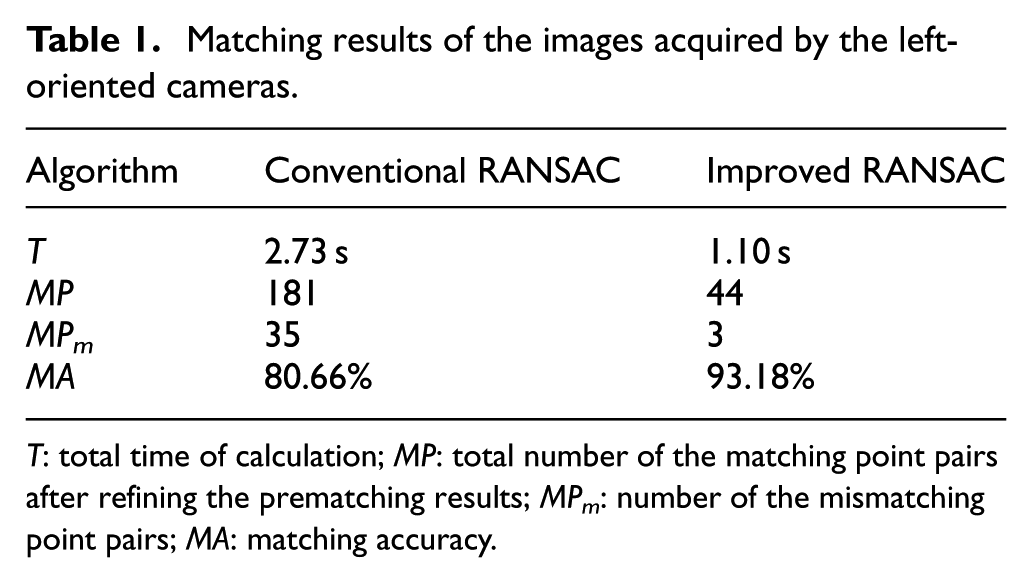
T: total time of calculation; MP: total number of the matching point pairs after refining the prematching results; MPm: number of the mismatching point pairs; MA: matching accuracy.
Matching results of the images acquired by the right-oriented cameras.
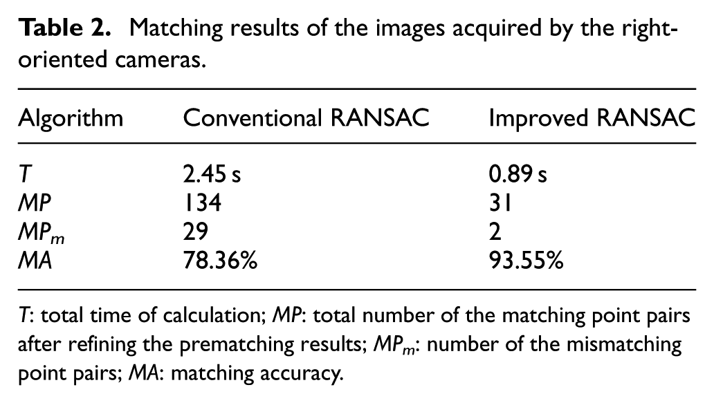
T: total time of calculation; MP: total number of the matching point pairs after refining the prematching results; MPm: number of the mismatching point pairs; MA: matching accuracy.
Matching results of the images acquired by the left-oriented camera and the right-oriented camera.
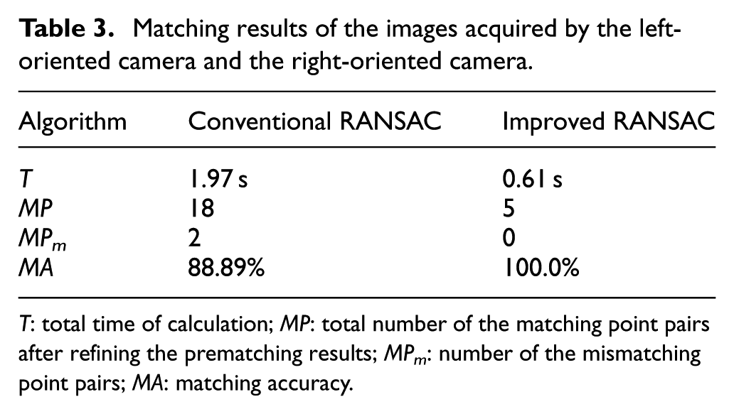
T: total time of calculation; MP: total number of the matching point pairs after refining the prematching results; MPm: number of the mismatching point pairs; MA: matching accuracy.
From the matching results in Figures 7–9 and Tables 1–3, we can see that for the problems of low-accuracy and time-consuming in matching due to lots of outliers in prematching data set of parallel robot images, the improved RANSAC algorithm can effectively improve the accuracy and speed of pose detection of parallel robot. The average time of the method based on the conventional RANSAC algorithm is 2.38 s, and the average accuracy is 82.64%. The average time of the proposed method is 0.87 s, and the average accuracy is 95.58%. Compared with the conventional RANSAC algorithm, the average time of the proposed method decreases by 63.45%, which improves the real-time performance of system. The average matching accuracy increases by 15.66% using improved RANSAC in experiments. From Tables 1–3, we can see that the time of pose detection can be decreased to 0.61 s, and the accuracy can be improved simultaneously. The proposed method reduces the time of end-effector pose detection for parallel robot based on binocular vision from second level to millisecond level, which can meet the time requirement of the servo cycle of parallel robot. It provides a feasible solution for real-time detection of end-effector pose of parallel robot.
We take out the mark points of end-effector from feature points, and take it into camera model to get the pose parameters. Specific operation is as follows: Experiments are accomplished by grouping according to the different deviation angle between the left and right cameras. The robot moves by fixed track and the images are acquired regularly. The pose parameters at each measuring point are got from the images based on the conventional RANSAC algorithm and the improved RANSAC algorithm, respectively. The result is compared with actual pose. The tracking errors can be calculated by Equation (18)
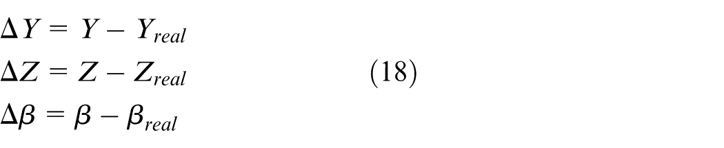
The
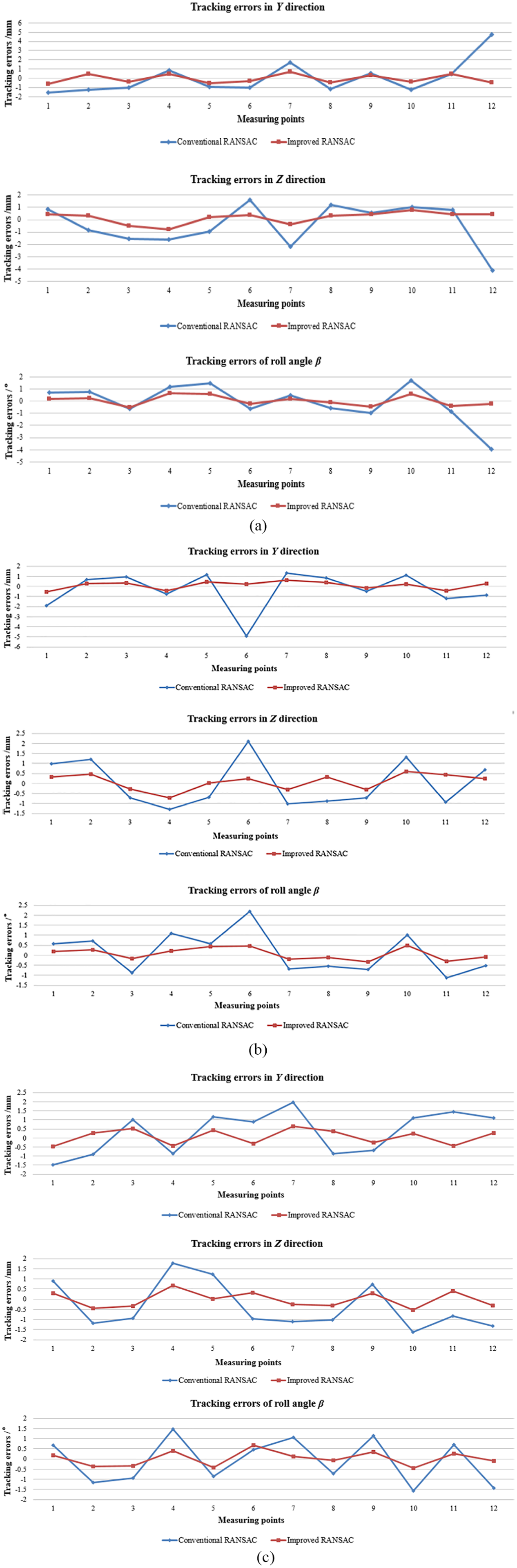
Pose tracking errors of parallel robot. (a) Tracking errors based on the images acquired by left-oriented cameras. (b) Tracking errors based on the images acquired by right-oriented cameras. (c) Tracking errors based on the images acquired by the left-oriented camera and the right-oriented camera.
Figure 10 shows that the tracking errors of P1 and P7 in the Y direction and the tracking errors of P4 and P10 in the Z direction are larger than others. In the above-mentioned measuring points, because of the significant change of direction, the changes of speed and acceleration are obvious. In addition, the inertia also can affect the pose accuracy. Figure 10 indicates that the movement trend of detection three-dimensional pose based on binocular vision in the experiments corresponds to actual pose.
Based on the conventional RANSAC algorithm, the gross errors occurred in P12 (Figure 10(a)) and P6 (Figure 10(b)), which come from mismatching. In addition, the average deviation of the measuring points can be got according to the tracking error. In the experiments based on the conventional RANSAC algorithm, the average deviation in Y direction is 1.278 mm, the average deviation in Z direction is 1.207 mm, and the average deviation of roll angle
From Figure 10, we can see that the tracking error and the average deviation are decreased using the proposed method. In addition, it can reduce gross error, which is easy to generate in pose detection based on the conventional RANSAC algorithm. Compared with the detection method, which is used in Sui et al., 32 the average deviation in Z direction is reduced from 4.09 mm to 0.387 mm. It shows that the improved algorithm not only improves the real-time performance, but also improves the accuracy of the pose detection.
In conclusion, the RANSAC algorithm proposed in this paper is adopted to refine the prematching results of Harris–SIFT operator. Then, the refined matching results are taken into the camera model, and the pose parameters of end-effector of parallel robot are obtained. As a result, the accuracy and speed of end-effector pose detection of parallel robot are efficiently improved.
Conclusion
In the end-effector pose detection of parallel robot based on binocular vision, the factors of complex image background, unobvious end-effector characteristics and uneven illumination make the image matching difficult to achieve accurately and rapidly, and affect the accuracy and real-time performance of pose detection. Therefore, in order to improve the accuracy and speed of end-effector pose detection of parallel robot based on binocular vision and further realize the closed-loop control of parallel robot, this paper improves the conventional RANSAC algorithm and proposes a pose detection method of parallel robot based on the improved RANSAC algorithm. The following conclusions can be drawn:
A method of selecting feature points in separated grids of images is proposed to improve the conventional RANSAC algorithm. It solves the problem of inaccurate fundamental matrix caused by random sample selection. It increases the sparsity of sample distribution and improves the accuracy of image matching.
A method of predetecting to validate provisional model is proposed to further improve the conventional RANSAC algorithm. It solves the problem that too much time is needed to look for the support set when there are many errors in observation data set. It reduces invalid calculation of the support set and improves the speed of image matching.
An image matching method based on Harris–SIFT algorithm and improved RANSAC algorithm is proposed. It solves the problem of mismatching in the prematching results of Harris–SIFT algorithm to improve the accuracy and real-time performance of matching.
Based on proposed image matching method, the end-effector pose detection of parallel robot is realized, which improves the accuracy and speed of pose detection. The proposed pose detection method of parallel robot was applied to a self-developed novel 3-DOF parallel robot to verify the validity. The experimental results show that, compared with the pose detection method based on the conventional RANSAC algorithm, the average deviations of end-effector poses in Y direction, Z direction and roll angle β decrease by 0.871 mm, 0.82 mm and 0.704° using the proposed pose detection method, respectively. The proposed pose detection method based on the improved RANSAC algorithm can improve the accuracy and speed of end-effector pose detection of parallel robot, which provides a feasible solution for real-time detection of end-effector pose for parallel robot. It also lays the foundation for further realizing the high-performance closed-loop control of parallel robot.
Footnotes
Declaration of conflicting interests
The author(s) declared no potential conflicts of interest with respect to the research, authorship, and/or publication of this article.
Funding
This work was supported by the National Natural Science Foundation of China (Grant 51375210); the Postgraduate Research & Practice Innovation Program of Jiangsu Province (Grant KYCX17_1780); the Zhenjiang Municipal Key Research and Development program (Grant GZ2018004); and the Priority Academic Program Development of Jiangsu Higher Education Institutions.