
Abstract
Hydrogen has been considered as a feasible energy carry for fuel cell vehicles, which offers a clean and efficient alternative for transportation. In the currently developed hydrogen compression cycle system, hydrogen is compressed through a compressor and stored in the tank as high pressure. The hydrogen is filled from high pressure station into hydrogen storage system in fuel cell vehicles. In the study, theoretical and simulation are performed by presenting a mathematical model for the temperature rise during filling process in the hydrogen storage tank at the pressure of 50 MPa compressed hydrogen system. For a high-pressure tank (HPT) that can store hydrogen at a hydrogen filling station, the temperature rise of hydrogen with the pressure change during the filling process, the amount of hydrogen filling in the tank, and the convective heat transfer coefficient in the tank were calculated. The calculated temperature was compared with numerical and theoretical methods. Appropriate theoretical formulas were presented through mathematical modeling for changes that occur when high-pressure storage tanks were filled, and hydrogen properties were analyzed using the REFPROP program. 3D modeling was performed for the high-pressure storage tank, and the analysis was conducted under adiabatic conditions. When the pressure was increased to 50 MPa in the initial vacuum state, and when the residual pressure was 18 MPa, it was 25, 50, 75,and 100 MPa, and hydrogen inside the storage tank of the temperature rise and the amount of hydrogen filling were investigated. The results of this study will be useful for the design and construction of compressed hydrogen tank for hydrogen charging system.
Introduction
The full-speed advancement of industrial modernization has led to the continuous growth of energy demand, the continuous increase of traditional fossil energy consumption, and the generated carbon dioxide and other pollutants, which have adverse effects on the sustainable development of human beings and nature.1,2 As a secondary energy with high calorific value, clean and easy storage and transportation, hydrogen energy can not only support the efficient utilization of traditional fossil energy, but also an important carrier for building a multi-clean energy supply system. Therefore, hydrogen energy is regarded as the future energy that leads the transformation and upgrading of the industry.3,4 Hydrogen energy vehicles are one of the areas with the greatest commercial value potential. Among them, hydrogen internal combustion engine vehicles and hydrogen fuel cell vehicles have good expected benefits and strong demonstration operation potential, while hydrogen fuel cell vehicles have attracted much attention due to their advantages such as fuel economy, short hydrogenation time, and long cruising range. In order to improve the energy density of high-pressure hydrogen storage and require the filling operation of high-pressure gaseous hydrogen to be completed in a relatively short time. Safety, economical and efficient on-board high-pressure hydrogen storage technology is an important guarantee for hydrogen fuel cell vehicles to achieve the goal of commercial operation. 5
The compression effect of hydrogen can generate a lot of heat; the negative J-T effect when the hydrogen passes through the throttle valve will further promote the generation of heat; when the high-pressure hydrogen enters the hydrogen storage tank, the kinetic energy of the incident flow is converted into heat energy: The above factors cause a significant temperature rise during the filling process of hydrogen storage tank. High temperature will adversely affect the mechanical properties of the hydrogen tank material and the filling efficiency of the gas cylinder; thereby affecting the life of the high-pressure hydrogen storage tank. 6 This paper discusses the previous review work from three aspects: theoretical modeling, experimental exploration, and numerical simulation.
Theoretical Analysis: The choice of the equation of state is a key to constructing a theoretical model. Farzaneh-Gord et al.7,8 used the first and second laws of thermodynamics to study the single-stage and three-stage fueling of hydrogen refueling stations and natural gas refueling stations, respectively. The results showed that single-stage filling takes less time than the three-stage filling. Kermani 9 proposed to replace solid pistons in conventional compressors with ionic liquids in hydrogen refueling stations. Olmos and Manousiothakis10–12 compared the molar volume, internal energy, enthalpy and other reference values provided by the National Institute of Standards (NIST) and Redlich Kwong (RK), Soave Redlich Kwong (SRK), and Peng Robinso (PR) to compare the thermal parameter values derived from the equation of state. It was found that the values provided by RK were closer to the reference values given by NIST than SRK and PR. However, the assumption that the gas heat capacity does not depend on temperature will cause prediction errors, and RK is not universal as an input model for simulating temperature rise. The heat transfer between the hydrogen and the inner tank wall is the key to the high-precision prediction of the theoretical model. When the computational fluid dynamics model calculates heat transfer by simulating the gas velocity near the tank wall, the thermodynamic model needs to add additional assumptions, thereby simplifying the complex heat transfer phenomenon in the actual filling process. 13 Woodfield et al., 14 Hosseini et al., 15 Sadi and Deymi-Dashtebayaz, 16 Wang et al. 17 used the correlation of dimensionless numbers (such as Nusselt number, Rayleigh number, Reynolds number) to correlate the effects of natural convection and forced convection were correlated, and the relationship between temperature and other physical parameters (such as pressure and mass) in the initial state and final state was obtained. Harty and Mathison 18 characterized the heat transfer process with a lumped parameter which calibration was based on experiments varying filling time, inlet temperature, and ambient temperature. However, Bourgeois et al. 13 pointed out that the above research results are often based on ideal assumptions, and the standard specifications and parameters of gas tanks are applicable to a limited range. In order to solve practical engineering problems, many researchers use a constant convective heat transfer coefficient to study the heat transfer between the hydrogen gas and the liner in the tank. Experimental study: Matsuno et al. 19 used the built test system to conduct more than 10 hydrogen cycle tests on two type tanks with a working pressure of 70 MPa. The results showed that after several cycles, the temperature of hydrogen was in fluctuates within a fixed temperature range. Acosta-Iborra et al. 20 used the GASTEF device built at JRC-IE to conduct a preliminary hydrogen cycle test on a 70 MPa, 29 L type IV tank, and provided the test results of the first cycle. Demaël et al. 21 proposed that the spatial distribution of the temperature rise in the tank is a key indicator for evaluating the temperature rise of hydrogen. Experimental studies by Kim et al., 22 Liu et al., 23 Dicken and Mérida, 24 Ortiz Cebolla et al., 25 and Melideo et al. 26 showed that: the temperature change of hydrogen storage cylinders has received extensive attention in academia. Heath et al. 27 conducted a hydrogen filling experiment and obtained the heat transfer coefficient of the real wall temperature. Numerical simulation: Hugo et al. 28 used MILP (Mixed Integer Linear Programming) method to establish the investment calculation model of hydrogen refueling station. The prediction accuracy of numerical simulation research is a hot spot in the study of temperature rise evolution. de Miguel et al., 29 Li et al., 30 Suryan et al., 31 Bourgeois et al. 32 used a two-dimensional axisymmetric model to numerically simulate type III and IV hydrogen storage cylinders, and compared with the experimental data. Zhao et al. 33 studied the filling process of 35 MPa under different initial pressure conditions. The study showed that the maximum temperature rise of the hydrogen storage cylinder was distributed at the bottom, and the maximum temperature rise decreased linearly with the increase of the initial pressure. Zhao et al. 34 conducted a numerical study of the 70 MPa fast charging process under different boost modes. The result shows that the difference in final gas temperature rise under different boosting methods is small. Zheng et al. 35 studied the effect of ambient temperature on the final temperature rise, and concluded that the final temperature increased almost linearly as the ambient temperature increased. Ramasamy and Richardson 5 investigated the filling process of hydrogen cylinders with three different inlet configurations and showed that peak hydrogen temperature can be reduced by distributing the hydrogen jet between different nozzles. In summary, many scholars have studied the relationship between the filling temperature rise and the initial pressure of hydrogen, the boost mode, the ambient temperature and other filling parameters, as well as the filling temperature rise and the length-diameter ratio of the gas cylinder, and the incident configuration of the gas cylinder. A large number of research results and valuable data have been obtained on the relationship between structural parameters. However, there are still some deficiencies, such as the comprehensive influence law of multi-parameter changes such as the pressure of the hydrogen storage tank on the temperature rise of the fast charging of the hydrogen cylinder is not clear. This paper will carry out research on this issue. The study results can improve the understanding of the temperature rise process of hydrogen fast charging for researchers and practitioners in the industry, and help to formulate and optimize the temperature rise control scheme of hydrogen storage system in the future.
The whole process of hydrogen refueling stations currently being developed uses a method of compressing hydrogen to high pressure by a compressor, and the compressed hydrogen temperature is lowered through a heat exchanger and stored in HPT. Compared to the storage cylinders installed in hydrogen fuel cell vehicles, the performance of the HPT at the hydrogen charging station is insufficient. In addition, there is very little research on the amount of filling and durability of the HPT at the hydrogen refueling station that provides fuel to the vehicle, and the risk associated with the pressure increase during charging.
During filling process, due to the repeated entry and exit of hydrogen heated at high temperature and high pressure, the fatigue accumulation inside the storage tank is very likely to explode. In relation to the danger of this storage tank, a chemical chain explosion of hydrogen occurs, causing the tank to rupture or the valve to break, so the possibility of a fire inside the tank is a high probability. In 2020, there was an incident in which eight people were killed and a building was destroyed due to the explosion of a HPT at hydrogen refueling station in Gangneung (Korea). Therefore, it is of practical significance to study the temperature rise of hydrogen in the tank
Experimental methods
Charging hydrogenation system
The high pressure hydrogenation station cycle system generally consists of hydrogen storage system, compression system, heat exchange system and charging hydrogen system. The hydrogen station test system, as shown as Figure 1. Figure 2 shows hydrogen storage tank filling system test platform.

The schematic diagram of hydrogen station system.

Hydrogen storage tank filling system test platform.
The filling experiment of hydrogen
The compression cycle in hydrogen filling returns to the process shown in Figure 1, a two-stage compressor, the compressed hydrogen storage tank were used in the experiment. The hydrogen gas in HST trailer is discharged and compressed by the compressor, the gas enters through the heat exchanger and enters the high pressure tank (HPT) (4), low-pressure buffer tank (10) through pipeline when the valve is opened. Heat is generated during the compression process, storing process and the process of passing the pressure reducing valve. Then, the heated hydrogen is cooled to an appropriate temperature through a heat exchanger. First stage and second stage mean compressors, and H/X is the heat exchangers. Several tests were conducted through two cycles to test the performance of the compressor and the pressure data of the high-pressure tank and buffer tank were obtained through the pressure sensor.
The conditions of HPT
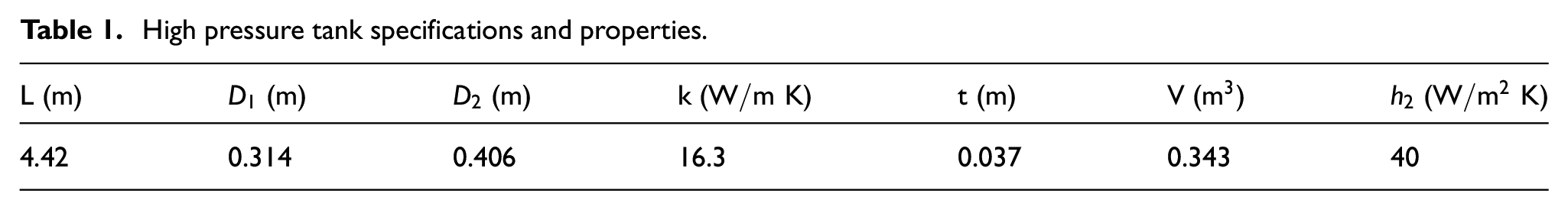
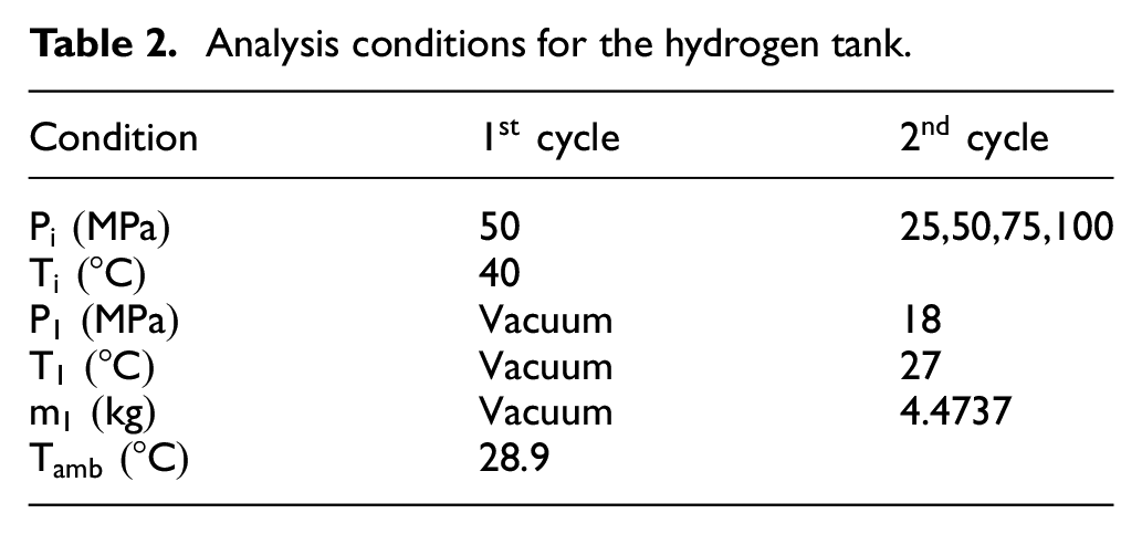
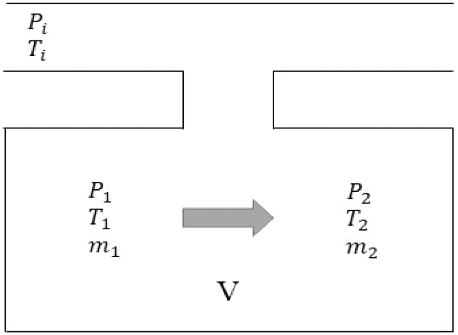
Table 1 is the HPT specifications and properties. 20 Analysis conditions for the hydrogen tank are given by Table 2. Figure 3 shows a HPT of schematic diagram. Compressed hydrogen filling diagram, as shown in Figure 4.
High pressure tank specifications and properties.
Analysis conditions for the hydrogen tank.

Geometry of HPT.
Compressed hydrogen filling diagram.
High pressure hydrogen storage tank analysis
Theory analysis of the hydrogen tank
The filling hydrogen process in the hydrogen filling storage is carried out in such a way that hydrogen, which has become high temperature and high pressure through multi-stage compression in the hydrogen filling station, it is lowered to a certain temperature through a heat exchanger and then stored inside the tank. When storage occurs, the temperature and pressure of hydrogen rise. Assumptions were made to theoretically calculate the temperature and pressure changed during storage.
- When filling, the temperature of hydrogen entering the tank is constant.
- There is no heat exchange between the container and the outside.
- The initial state in the container is a vacuum state, and the pressure and temperature are constant.
- Ignore potential energy changes and kinetic energy changes.
- The temperature outside the tank is fixed at 28.9°C (The average summer temperature)
The flow direction of hydrogen proceeds from the hydrogen cartridge to the tank, and when hydrogen is charged into the tank under the assumption condition, the final temperature expression of the hydrogen after the filling is obtained through the mass and energy conservations. The governing equations are as follows:

Real gas equation of state is as followed 21 :

When the hydrogen in the tank is charged from A (Hydrogen cartridge) to B (Hydrogen cylinder), both sides of equation (1) are differentiated with time:

It can be expressed by equation (4). When potential energy and kinetic energy are constant and the power that the hydrogen exudes on the external environment is zero (

According to equations

High pressure tank in vacuum
Equation (6) can be used to obtain the temperature after charging is complete.

The second cycle analysis of the tank
When there is no heat exchange with the outside in the tank, and it is an actual gas and adiabatic process. By substituting the condition into equation (5) to obtain the final temperature inside the tank after filling is complete:

Equation (7) can be used to obtain the temperature after charging is complete.
Convection heat transfer coefficient inside the tank
We use the formula to calculate the actual heat transfer coefficient between the wall and the hydrogen, and use this actual heat transfer coefficient to simulate the actual filling process, then compare the numerical results with the theoretical data.

Additionally, to calculate the convective heat transfer coefficient, REFPROP was used for the necessary hydrogen properties.
Heat transfer rate and wall temperature
Heat transfer in the storage tank for hydrogen filling occurs on the surface of the storage tank and takes place in a complex form of conduction, convection, and radiation (Figure 5). However, radiation heat transfer between the gas and wall is assumed to be negligible since temperature difference between the gas and inner walls is very small. The total heat transfer rate from the center of the container to the outside air is equal to the sum of the cylindrical part and both sides, and can be expressed by equation (9).

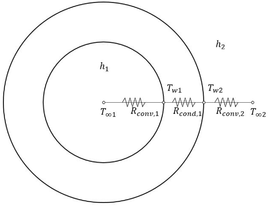
Heat resistance circuit for high pressure tank. 36
Since the total heat transfer rate

Results and discussion
Theoretical analysis of HPT
Table 3 is the HPT analysis results for the hydrogen cycles. Experimental data of pressure for the second cycle, as shown in Figure 6. Figure 7 is Variation of the pressure and theoretical temperature for the second cycle: (a) HPT; (b) Buffer tank.
High pressure tank analysis results.

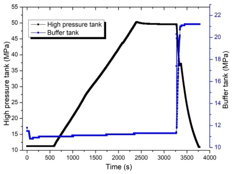
Experimental data of pressure for the second cycle.

Variation of the pressure and theoretical temperature for the second cycle (a) HPT (b) Buffer tank.
Numerical analysis of HPT
Comparison of the final temperature of the fluid under the charging pressure and mass with the analytical method and the numerical method, as shown in Table 4.
Comparison of the final temperature of the fluid under the charging pressure and mass with the analytical and the numerical analysis.

The maximum temperature inside the high-pressure tank was compared through a theoretical method and a numerical method. When a residual pressure of 18 MPa exists and the filling pressure is 25 MPa, the temperature of hydrogen inside the vessel is 52.18 °C, the theoretical method is numerically. The method is 56.85, respectively 98.55 °C and 106.85 °C at 50 MPa, 124.58 °C and 126.85 °C at 75 MPa, respectively, 132.4 °C and 136.85 °C at 100 MPa. When the pressure was increased to 50 MPa in the initial vacuum state, they were calculated as 165.26 °C and 158.85 °C, respectively, and the maximum error rate of the analytical method and the numerical method was analytically derived from equation (7) in the cycles.
The variation of temperature distribution during the filling process is shown in Figure 8. As shown in this figure, the temperature in the tank shows a rising trend in the hydrogenation process. The temperature distribution in the tank is analyzed with examples in the process of hydrogen filling from 18 to 100 MPa. The initial temperature of the system is 27 °C. Figure 8(a) shows the temperature cloud of the XY plane at charge pressure 25 MPa. The temperature in the tank continued to rise during the process, and the lowest temperature was observed near the inlet pipe outlet. The injected gas heated up rapidly due to the heat transfer of pre-filled hydrogen, and the high temperature appeared at the end of the tank. Figure 8(b)shows the distribution of temperature under charge pressure 50 MPa. It is also obvious that the temperature is the highest in the tail of the tank. At the same time, the gas of inlet tube is inclined downward due to gravity. While due to the buoyancy effect, the temperature at the top of the tail is slightly higher than bottom. The temperature distribution in the tank is not uniform. The trajectory of hydrogen temperature can be seen from Figure 8. Hydrogen injected from the intake pipe impinges on the wall of the cylinder and forms a large recirculation flow near the tail.

The temperature distribution in the high pressure storage tank from 18 to 100 MPa: (a) at charge pressure 25 MPa, (b) at charge pressure 50 MPa, (c) at charge pressure 75 MPa, and (d) at charge pressure 100 MPa.
Conclusion
In injecting compressed hydrogen into HPT which is formed of hydrogen, the changes of temperature and pressure, charge volume, internal and external temperature of HPT were explained. The process of high pressure storage tank used in hydrogen stations was studied by analysis and numerical methods.
As a result, the conclusions are drawn:
(1) The convective heat transfer coefficient inside the tank was calculated as 113.49
(2) The maximum temperatures of hydrogen inside HPT were calculated to increase by 165.26 °C and 98.55 °C in the first cycle and the second cycle, respectively.
(3) The analysis showed that the mass of hydrogen charged from the first cycle of the HPT to the inside of the HPT was 9.4851 kg, 4.4217 kg in the second cycle.
(4) The temperatures of the inner and outer walls of HPT were calculated as 146.61 °C and 71.12 °C in the first cycle, and 89.02 °C and 50.47 °C in the second cycle.
(5) The results obtained by the numerical method and the analysis method show a difference of within ±2.2%.
(6) The numerical result shows that the temperature and the mass of injected hydrogen increased as the residual capacity of hydrogen is smaller.
The result of this study will be useful for the design and construction of hydrogen charging system. At the same time, it can provide theoretical guidance for the formulation of hydrogen fuel vehicle storage system related technical requirements and standards, provide technical support for the strategy optimization of hydrogenation machine, promote the development of rapid hydrogenation technology of hydrogenation station, and accelerate the layout of hydrogen society.
Outlook and future perspectives
This paper mainly focuses on the establishment of theoretical models and numerical simulation research, and the experimental research is rarely involved. The following aspects should be paid attention to in the future study: (1) At present, there are relatively few experimental data available. In the future, a large number of numerical simulations can be carried out for different types of hydrogen storage cylinders, and more temperature rise data can be obtained and used to correct the correlation formula of the temperature rise, and finally a temperature rise prediction formula can be formed. (2) A smart hydrogen storage tank actively cooled during charging hydrogenation. (3) A new type of thermally conductive 70 MPa on-bus hydrogen storage tank without pre-cooling equipment. (4) Development of a passively cooled internal hydrogen storage tank to reduce hydrogen refueling infrastructure costs. (5) Identifying early damage to high pressure hydrogen storage cylinders using material properties of monitoring and defect formation
Footnotes
Appendix
Acknowledgements
We tank School of Transportation, Ludong University for providing an academic license of Solidworks and Fluent for simulation.
Handling Editor: Chenhui Liang
Declaration of conflicting interests
The author(s) declared no potential conflicts of interest with respect to the research, authorship, and/or publication of this article.
Funding
The author(s) disclosed receipt of the following financial support for the research, authorship, and/or publication of this article: This research was supported by Ludong University Talent Research Start-up Funding (No.20220035).