
Abstract
This article presents a numerical analysis and experimental study on condensation heat transfer and fluid flow for filmwise condensation on trapezoid grooved surfaces. First, a physical model was properly simplified based on some reasonable assumptions. Then, the coupled non-linear governing equations for the mass transfer, fluid flow, and two-dimensional thermal conduction were developed. The relationship between z-coordinate and heat transfer was obtained by solving the equations numerically. The influences of groove length and basic angle were discussed. The calculation results showed that the heat flux decreased with increase in groove length, and the decline range also decreased gradually. The calculation results also suggested that the heat flux through groove with α = 60° was lower than the groove with α = 75° at the top of the groove, while the opposite conclusion was obtained at the low parts. The distributions of wall temperature and heat flux on trapezoid groove were also studied systematically. The distribution of surface temperature and heat flux presents obvious lateral inhomogeneity, and the maximum wall temperature and heat flux were both obtained in region II. The thermal resistance of groove with α = 60° was lower but the liquid-discharged ability was better than that of groove with α = 75°. In order to validate the feasibility and reliability of the present analyses and to further investigate the heat transfer performance of trapezoid grooved surfaces, experiments were carried out with three condensing plates including two trapezoid grooved surfaces in different physical dimensions and one smooth surface. The experimental data obtained under various schooling were compared with the calculations, and the experimental results for different condensing plates are all in good agreement with the numerical model, with a maximum deviation less than 15%. Moreover, the trapezoid grooves can enhance the condensation heat transfer by 1.5–2.5 times higher than the smooth surface. The present analyses are feasible and can be used in the parameter design and heat transfer calculation of trapezoid grooved surfaces.
Keywords
Introduction
Condensation involves change of phase from the vapor state to the liquid. It is associated with mass transfer, during which vapor migrates toward the liquid–vapor interface and is converted into liquid. Condensation of vapor is widely used in industrial applications that require high heat transfer rates such as desalination, chemical engineering, refrigeration, and power generation owing to its high heat transfer coefficient. When vapor comes in touch with a surface below the saturation temperature, filmwise condensation is preferred when the liquid wets the condenser surface, resulting in the complete coverage of the surface by a liquid film. Filmwise is commonly observed in various phase change heat transfer devices. During this process, film is removed from the surface under the action of the gravity and shear stresses due to vapor flow, and the film renders a high thermal resistance to heat transfer and therefore a relatively large temperature gradient prevails across it.
In order to reduce the thermal resistance and enhance the heat transfer of filmwise condensation, many methods were developed, and several excellent researches of this topic have been reported both in experimental results and numerical simulations.1–4 Among them, utilizing the effect of surface tension to enhance the heat transfer of filmwise condensation on a vertical grooved surface was one of the most effective methods. 5 In filmwise condensation, the thickness of liquid film strongly affects the heat transfer. It is expected that the heat transfer during filmwise condensation would be enhanced if the liquid film is thinner. The adoption of grooved surface can make the liquid film thinner locally by utilizing surface tension and therefore is recognized as an effective method for enhancing the heat transfer of filmwise condensation. A theoretical formula to calculate the thickness of laminar film on the crest of grooves was first proposed by Gregorig, 6 but the procedure required for design of the groove shape was not reported in their research. Thereafter, much research of filmwise condensation on grooved surfaces has been conducted, and several shapes of grooves, such as triangular, 7 sinusoidal, and rectangular,8,9 were developed.
Mori et al. 7 investigated the condensation on triangular, wavy, and flat bottomed grooves with theoretical analysis and experiments. An empirical equation for calculating the thickness of liquid film on the crest of the grooves was established, and average heat transfer coefficient was obtained by numerically solving the equation. The experimental results for triangular grooves verified the accuracy of the analyses. Park and Choi 8 investigated the condensation on triangular grooves. They developed a three-dimensional heat transfer equation to calculate the condensing film flowing down along a vertical grooved tube. The continuity equation, Navier–Stokes equation, and energy equation were solved using a SIMPLE-type finite volume method. The calculations were in excellent agreement with the data from Gregorig. 6 Bilen et al. 9 performed an experimental study on surface heat transfer for different geometric groove shapes (circular, trapezoidal, and rectangular). Among the grooved tubes, heat transfer enhancement was obtained up to 63% for circular grooves, 58% for trapezoidal grooves, and 47% for rectangular grooves, in comparison with the smooth tube at the highest Reynolds number (Re = 38,000).
Garg and Marto10,11 established the equations of fluid mechanics and thermal conduction for condensation on sinusoidal grooves by establishing a curvilinear cylindrical coordinate system based on tensor analysis and boundary layer theory. The linear extrapolation of the results obtained by solving the equations with finite difference method showed a fairly good agreement with experimental data. Honda and colleagues12,13 studied the condensation on sinusoidal grooves. The basic equations, used to describe the distribution of film thickness both on crest and in grooves, were set up and solved with numerical method. The results agreed well with the experimental data. Zhu et al. 14 numerically studied the heat transfer of filmwise condensation on a vertical sinusoidal grooved tube. The calculation results were in good agreement with the experimental data, and they claimed that the equation can be used in the parameter design of sinusoidal grooved tubes and other types of grooved tube such as triangular shape and rectangular shape. Park 15 conducted a three-dimensional numerical investigation of the flow, heat, and mass transfer characteristics of the grooved tube with films flowing down on the outside tube walls. The velocity and temperature fields were successfully predicted for various groove shapes using the moving-grid technique.
Present experiments and simulations showed that trapezoid grooves have better performances in evaporation16,17 and capillary18,19 than other shapes of grooves. However, little research has been conducted on the enhancement of filmwise condensation heat transfer of trapezoid grooved surface compared with wavy grooved surface, triangular grooved surface, and grooved surface. In this study, theoretical analysis is carried out for laminar film condensation on trapezoid grooved surface. A convenient procedure for calculating condensation heat transfer on trapezoid grooves is presented based on previous works. Experiments are performed on two trapezoid grooved plates and smooth plate. The experimental data are compared with analytical results to investigate the feasibility of the analysis and the condensation performance of trapezoid grooved surfaces.
Theoretical analysis
Physical model
The physical model of the grooves is schematically shown in Figure 1(a). Several isosceles trapezoid grooves are machined vertically on the condensing surface, and the cooling surface is flat. The trapezoid’s basic angles are α, and the pitch and the height of grooves are P and h, respectively. Owing to the good symmetry of the groove cross section, only a half of the cross section and coordinate systems are considered for simplification, as shown in Figure 1(b).
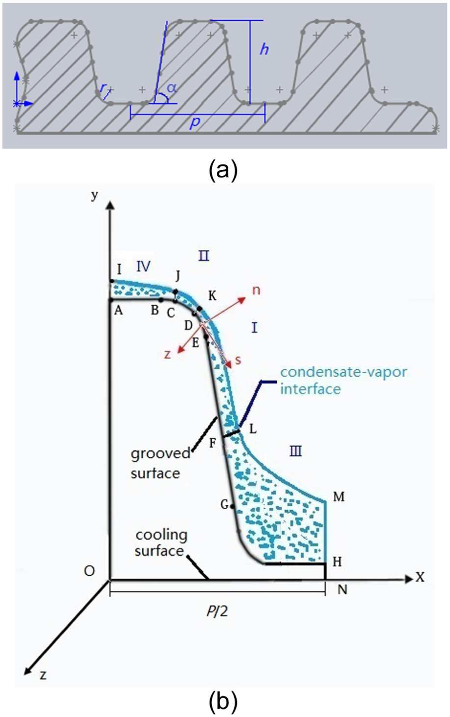
Physical model of the grooves and coordinate systems: (a) Physical model and (b) coordinate systems.
In the simplified geometry model, the grooved surface is denominated in A-H, and the interface of condensate–vapor is denoted by I-M. The cooling surface is described by ON, and IAO and MHN are symmetric boundaries. The bottom of the groove denoted by GH is semicircle shaped to facilitate the machining. The crest is connected smoothly with the trough by an arc denoted by B-E.
The liquid will flow in the horizontal direction due to the difference in the grooved surface curvature. We assume that the liquid flows from the starting point D, the central point of arc B-E, to both sides, and therefore the liquid film can be divided into four different regions: region I is the area enclosed by DFLK, region II is bounded by the closed curves CDKJ, and regions III and IV are surrounded by FHML and ACJI, respectively. The liquid film in regions I and II is thin, while thick in regions III and IV. The condensate–vapor interfaces in adjacent regions are connected smoothly with each other. An orthogonal curvilinear coordinate system (n, s, z) is established. In the coordinate system, n is the normal direction of the groove surface, s is the length of arc along the groove surface, and z is the vertical direction.
The numerical model presented in this article is based on the following assumptions:
The vapor velocity near the condensate is very low, so the effect of interfacial shear between the vapor and liquid film can be neglected.
The slip flow of laminar condensate in groove is in a slow and steady condition, so that the convective term together with inertia term in the momentum equations are negligible.
The variation of longitudinal curvature of the liquid film is far less than that of horizontal curvature and can be neglected.
The thermal conduction within the liquid film along the gravitational direction is neglected.
The contour of condensate in regions III and IV is assumed to be a circular arc shape.
Fundamental equations
Regions I and II
The liquid film in these two regions is much thinner than that in other regions, and the fundamental equations are established based on the boundary layer theory. Using the assumptions above, the inertia, convective, and relatively small terms can be neglected. The fundamental equations are written as


The boundary conditions are written as


Integrating equations (1b) and (1d) with boundary conditions (2), and substituting the solutions into the continuity equation (1a), the liquid film thickness equation is obtained as follows

Equation (1c) indicates that there is no pressure change along the normal direction (n) of the liquid film, so the pressure within the liquid film is equal to the pressure at the interface. The interface pressure between liquid film and vapor can be obtained from

Substituting equation (4) into equation (3), neglecting the second term on the left side to simplify the equation, we can obtain

Equation (5) for the determination of condensate film thickness
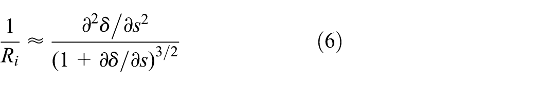
Substituting equation (6) into equation (5), we obtain the equation for calculating the thickness of the liquid film in regions I and II

The boundary conditions are


where
Regions III and IV
In these two regions, the liquid film is thick compared to that in regions I and II. Using assumption (5), the contour of liquid film can be considered as approximate circular arc shape under the action of surface tension, so the curvature of the interface approaches a constant. The horizontal driving force decreases sharply in regions III and IV and much smaller than the action of gravity. Therefore, the liquid flows mainly along the gravity direction rather than along the horizontal direction. Neglecting transverse flow of condensate and assuming that there is only z-direction flow in regions III and IV, the momentum equation can be expressed as
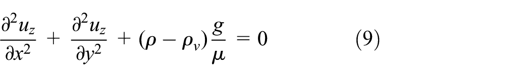
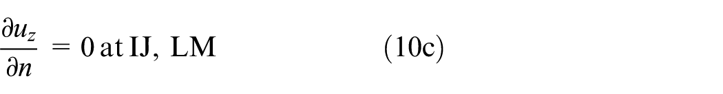
The boundary conditions are


Thermal conduction equation
On the basis of assumption (4), only two-dimensional thermal conduction needs to be considered in the numerical analysis process. The thermal conduction equation within groove and liquid film can be written as

The boundary conditions are


Solving procedure
The solving procedure includes at least seven key steps, which are as follows:
1. The subcooling temperature between the vapor and the substrate surface is defined as
2. Solving equation (7) subject to boundary conditions of region II at point D determined based on the result of region I, the interface of JK is obtained.
3. The vapor–liquid interface for two neighboring regions is smoothly connected with each other, and the contour of liquid film of regions III and IV is approximately of the arc shape. Therefore, the interface LM and IJ in regions III and IV can be determined, respectively.
4. Based on the determined vapor–liquid interface I-M, the temperature distribution
5. According to the interface temperature distribution in liquid film obtained from steps (1) to (4), the temperature gradient
where D is the length of the curve A-H.
6. Based on the finite element method, we obtain

where
The total mass flow rate of regions III and IV is

7. When the length of the groove is z, the amount of heat transfer rate is

Taking the derivative of equation (16) with respect to

The boundary conditions are


Method of defining kL.
The relationship between heat transfer rate Q(z) and coordinate values z can be obtained through solving equation (17) subject to equation (18) with the Runge–Kutta method. During solutions, the values of
Experiments for condensation heat transfer
Experimental apparatus and heat transfer plates
The experimental apparatus, shown schematically in Figure 3, consists of four parts: the steam generating system, cooling system, steam condensing system, and data acquisition/control system. Steam at about 100°C was supplied from a steam generator and then passed through a superheater to remove mist. The dry steam was led into the condensing chamber and condensed on the surface of the test condensing plate. The steam velocity in the duct was obtained by dividing total flow rate of steam through the duct by the cross-sectional area and was maintained at approximately 5 ± 0.5 m/s. The steam temperature was measured by a platinum resistance thermometer (Pt 100), with an accuracy of ±0.1°C. The steam pressure was monitored by a manometer and maintained at atmospheric pressure by adjusting the valve installed at the outlet of the condensing chamber. The condensing chamber is shown in Figure 4. This condensing chamber can freely adjust angle (from horizontal to vertical) by rotating device to satisfy experiment requirement. A baffle was set at the top of the condensing plate to eliminate the sweep effect of steam flow to the condensation droplets. The condensate on the test surface was collected by a funnel and then flowed into a measuring tube.

Schematic diagram of the experimental apparatus.

Photograph of the condensing chamber.
A window was mounted at the chamber for visual observation of the condensation process. The chamber was insulated by rock wool with thickness of 50 mm to diminish the condensation that occurred at other surfaces. By doing this, the influence of the unwanted condensation was very limited and can be neglected in the experiments. The excessive steam and the condensate condensed on the other surfaces of the condensing chamber flowed into an auxiliary condenser and were collected by another measuring tube. Water was used to cool the test surface. It was kept at a constant temperature in a cooling-water tank and was sprayed on the backside of the test condensing plate by means of a pump and a nozzle. Heat flux through the heat transfer plate was regulated continuously by adjusting the pressure and flux of cooling water. The inlet and outlet water temperatures were also measured by two platinum resistance thermometers (Pt 100). The uncertainty of temperature measurement was estimated as ±0.1°C.
Schematic diagram of the condensing plates was shown in Figure 5. Each plate was made of 4.0-mm-thick low-carbon steel. The condensing surface had an area of 50 mm × 50 mm and 20 trapezoid grooves. Each groove was h = 1.25 mm deep, with pitch P = 2.5 mm. The basic angles were 60° (no. 1) and 75° (no. 2) for different plates. The radii of the arcs B-E and G-H were both 0.3 mm. Two holes of 1 mm in diameter were drilled at the condensing plate. Their depths were 15 and 25 mm, respectively. Two sheathed copper–constantan thermocouples (type T, Omega Engineering Inc.) were inserted into the two holes to measure the wall temperature. The uncertainty of temperature measurement was estimated as ±0.1 K. Experimental data were collected using Agilent 34970A data acquisition unit, and all data including pressure, thermocouple readings, surface subcooling temperature, heat flux, and condensation heat transfer coefficients can be calculated by data reduction software, and the real-time data profiles can be displayed on computer monitor. The total systematic errors caused by the thermometry, flow measurement, and quality of condensate are no more than 10%.

Schematic diagram of the condensing plate.
Experimental data reduction
The heat transfer coefficient h is defined as
In order to calculate the heat transfer coefficient with equation (19), it is necessary to obtain the heat flux q and surface temperature Tw. In this research, the heat produced by condensation on the condensing surface was transferred to the cooling water through the heat transfer plate.
The heat transfer rate calculated from the amount of the condensate per unit time can be expressed as

and the heat transfer rate calculated from the flow rate and temperature increment of the cooling water was obtained from the following equation

The difference between Q1 and Q2 was less than 5%, and therefore, it is reasonable to calculate the heat flux through the grooved surfaces using the following equation

where Ag is the area of the grooved surface, and it can be calculated with the trapezoid’s basic angles and the pitch and the height of grooves.
For the smooth surface, the heat transfer can be obtained from

where As is the area of the smooth surface.
The temperature of the condensing surface Tw was calculated from equation (23) using the heat flux q obtained from equation (22)

where Δl is the distance between the condensing surface and the measuring points of the sheathed thermocouples inserted into the heat transfer plate.
Results and discussion
Analysis of influencing factors
The relationship between heat flux q and groove length z is demonstrated in Figure 6. The heat flux decreases with increase in groove length under various temperature differences, and the decline range also decreases gradually with the increase in groove length. It is mainly because that the thickness of liquid film increases along with the z axis, and the bottom of groove is covered by the condensate gradually. This process is in good agreement with universal understanding. From the comparison between two grooves with basic angle α = 60° and 75°, it can be found that the heat flux through groove with α = 60° is lower than the groove with α = 75° at the top of the groove, while at the low parts of the groove, the heat transfer of α = 60° is over the heat transfer of α = 75°. This suggests that the liquid-discharged ability of groove with α = 60° is better than that of groove with α = 75°. Figure 7 shows the velocities of condensate in the concave drainage channel. The calculation results also suggest that the flow rate in drainage channel of α = 60° is greater than that of α = 75°. In addition, the velocities increase with the increment in groove length.
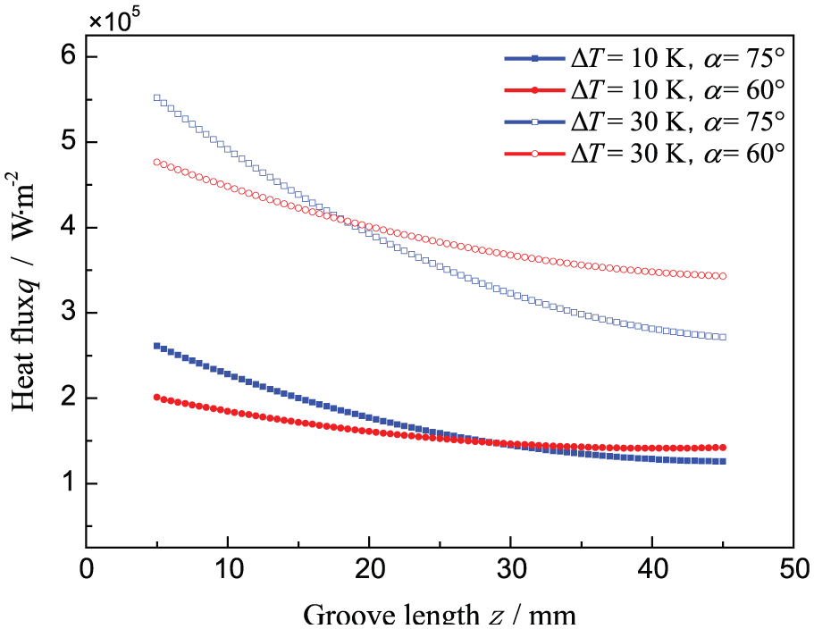
Relationship between heat flux and groove length.

Relationship between velocities and groove length.
Figures 8 and 9 show the distribution of wall temperature Tw and heat flux q on various trapezoid grooves. Through analyzing the trends of temperature curves and heat flux curves, it can be found that the distribution of surface temperature and heat flux presents obvious lateral inhomogeneity. Initially, both curves increase in regions IV and II and then decrease in regions I and III, and the maximum wall temperature and heat flux are both obtained in regions II, owing to its thinnest of liquid film. Moreover, wall temperature in regions I, II, and IV are higher than in region III, the similar trend is also followed by the heat flux. It is mainly because that the liquid film is much thicker in region III, and the thermal resistance of this region is larger than other regions, so the heat flux mainly through the groove in regions I, II, and III. By comparing the wall temperature and the heat flux between the grooves with α = 60° and 75°, it can be found that both the wall temperature and the heat flux in regions I and II are slightly higher for grooves with α = 75°. The proposed reason for this is that the larger basic angle of grooves causes a greater curvature change and higher surface tension to the condensate film on the shoulder of the crest in regions I and II, so the liquid film is thinner for grooves with α = 75°. The heat flux will increases with the decrease in the liquid film thickness, and wall temperature is also subject to the same rule. But in region III, the interface between the liquid and condensing surface is less for grooves with α = 60° even for the same amount of condensate, so the interface friction is lower. That is to say, the flow rate in drainage channel of α = 60° is greater than that of α = 75° and a thinner liquid film cover on the bottom of grooves with α = 60°. Therefore, the wall temperature and the heat flux in this region are higher for grooves with α = 60°.
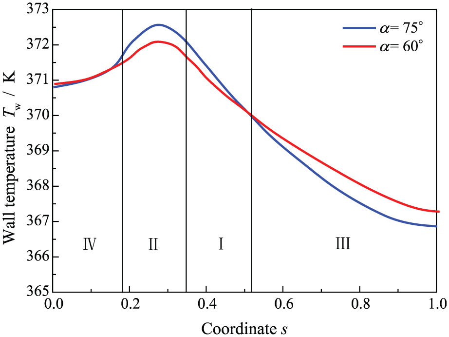
Distribution of wall temperature on trapezoid groove.
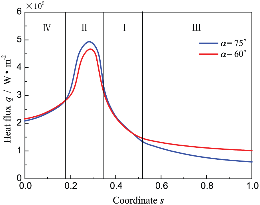
Distribution of heat flux on trapezoid groove.
Comparison between calculations and experiments
Figure 10 shows the typical condensation form occurring on grooved surface with basic angle α = 60° (no. 1) at

Photograph of condensation on grooved surface (no. 1, ΔT = 16.7 K, α = 60°).
Figure 11 shows the condensation phenomena on grooved surface with basic angle α = 75° (no. 2) at

Photograph of condensation on grooved surface (no. 2, ΔT = 17.2 K, α = 75°).
Figure 12 illustrates the comparison of heat flux between the calculations and experimental data for various grooved condensing plates. Besides, calculated values based on Nusselt model and the experimental results of smooth surface are also illustrated in this figure. Comparing the heat flux obtained from Nusselt model with empirical results of smooth surface, we find that the calculations agree well with the experimental results. This indicates that the test system is stable and reliable. As shown in Figure 12, the heat flux increases as the subcooled temperature increases for experimental values in the range of experimental temperature difference, and also the calculations follow the same trend. The calculations and the experimental values are in good agreement with a maximum deviation of 15%. It is proved that the present theoretical analysis about heat transfer of filmwise condensation on a trapezoid groove is feasible. The trapezoid grooved surface could enhance the heat transfer by about 1.5–2.5 times higher than smooth surface (no. S), so we validate that the adoption of trapezoid grooves can enhance the heat transfer of filmwise condensation by experiments.
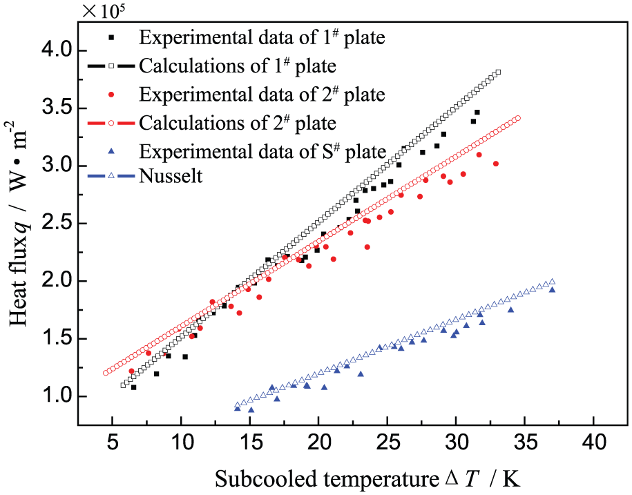
Comparison of heat flux between calculations and experimental values.
The comparison between two experimental data indicates that the heat flux through no. 1 grooved surface is lower than no. 2 grooved surface when ΔT < 15 K, while ΔT > 20 K, the heat transfer on no. 1 grooved surface is over no. 2, as shown in Figure 12. The reasons of these phenomena are as follows: (1) The volume of condensate is small under low subcooling, and flow rate of condensate in drainage channel has little or no effect on the heat transfer process. The thickness of liquid film is the main factor that affects the thermal resistance of condensation, thus the heat flux is higher on no. 2 grooved surface for its thinner liquid film on crest. (2) The influence of flow rate increases with the increase in temperature difference and gradually became the primary factor influencing the heat transfer process, whereas the thermal resistance of liquid film becomes less important, especially under large subcooling.
In order to understand the condensation phenomena deeply, the relationship between heat flux and basic angle at different surface subcoolings is plotted in Figure 13 in the range of 45° < α < 90°. The calculation curves show that the heat flux has approximately linear relation to the basic angle of trapezoid groove. The heat flux increases slightly with temperature difference when ΔT = 10 K, and the basic angle shows minor effect on heat flux under this condition. Whereas when ΔT = 30 K, the heat flux influenced distinctly by the basic angle, and the heat flux decreases with increase in basic angle obviously. Two major factors causing the variation trend of heat transfer characteristic curves have been found. In theory, the calculations show that the condensing surface increases gradually with the increase in the basic angle, and the heat transfer process is enhanced. From the observation and analysis of experiment, when the temperature difference increases, the area covered by deep liquid film (in region III) increases, and this means that the efficient condensing surface is decreased and the heat transfer is degenerated. Therefore, when ΔT = 10 K, the enhancement of condensing surface from basic angle may be larger than the decrement caused by deep liquid film resulting in a slight enhancement of heat transfer. But for ΔT = 30 K, the degeneration from deep liquid film will play a dominant role during the process of condensation, so the heat transfer decreases gradually. In addition, the basic angle has little impact on heat flux under the condition of ΔT = 20 K owing to the balance of the two factors. The conclusions above can be supported by the experimental data and calculation results illustrated in Figure 12.

The relationship between heat flux and basic angle.
Conclusion
Heat transfer of filmwise condensation on a trapezoid groove has been studied in the present dissertation by the numerical method. The coupled analysis of two-dimensional thermal conduction and fluid flow equations was established. By numerically solving the equations, the calculations of heat flux for trapezoid grooved plates were obtained. The influences of basic angle and groove length were discussed, and the distributions of wall temperature and heat flux on trapezoid groove were also studied systematically. The experimental apparatus was set up. The experimental data of heat flux for two trapezoids grooved plates as well as smooth plate were obtained under various temperature differences. The calculations were compared with the experimental data. The following conclusions can be obtained from the above studies:
The difference in surface tension of the liquid film can pull the liquid flowing from the crest into the trough, so that the liquid film on the crest became very thin. Therefore, the condensation heat transfer was enhanced. The trapezoid grooved surface can enhance the heat transfer by at least 1.5 times compared with the smooth surface.
The heat flux decreased with increase in the groove length under various temperature differences, and the decline range also decreased gradually with the increase in groove length.
The distribution of surface temperature and heat flux presented obvious lateral inhomogeneity. Initially, both the curves increased in regions IV and II and then decreased in regions I and III, and both the maximum wall temperature and heat flux were obtained in region II.
The heat flux through the grooved surface with α = 60° was lower than the grooved surface with α = 75°when ΔT < 15 K, while the opposite conclusion was obtained when ΔT > 20 K.
The thermal resistance of groove with α = 60° was lower but the liquid-discharged ability was better than that of groove with α = 75°.
The calculations follow the same trend as experimental data. The results were in good agreement with a maximum deviation of 15%. The present analyses are reliable and can be used in the parameter design and heat transfer calculation of trapezoid grooved surfaces.
Footnotes
Appendix 1
Academic Editor: Chin-Lung Chen
Declaration of conflicting interests
The author(s) declared no potential conflicts of interest with respect to the research, authorship, and/or publication of this article.
Funding
The author(s) disclosed receipt of the following financial support for the research, authorship, and/or publication of this article: The authors are grateful to the financial supports by the National Natural Science Foundation of China under grant no. 51306141 and the Specialized Research Fund for the Doctoral Program of Higher Education under grant no. 20120201120068.