
Abstract
During the fast filing process, thermal stress is generated due to the increase in the pressure and temperature of hydrogen in the hydrogen storage tank. For its safety purpose, it is necessary to predict and control the temperature change in the tank. The aim of this study is quantitative analysis of the final temperature and the mass of the hydrogen in the tank through experimental and theoretical methods. In this paper; Theoretical model for adiabatic and non-adiabatic real filling processes of high pressure hydrogen cylinder has been proposed. The cycle of filling process from the initial vacuum state is called the “First cycle.” After the first cycle is completed, there is a certain residual pressure in the tank. Then the second filling process called “Second cycle” begins. The final temperature in fast filling of hydrogen storage cylinders depends on targeted pressure, initial pressure and temperature, and mass filling rate. The final temperature of hydrogen in the tank was calculated from the real gas equation of state, mass and energy conservation equations. As a result of the analysis, based on the first cycle analysis of high pressure tank, the final temperatures were calculated to be 442.11 K for the adiabatic filling process, and 422.37 K for the non-adiabatic process. Based on the second cycle analysis of high pressure tank, the final temperature were obtained as 397.12 K and 380.8 K for the adiabatic and non-adiabatic processes, respectively. The temperatures calculated from the theoretical non-adiabatic condition were lower than those from the adiabatic condition by 5%. The results of this study can provide a reference basis in terms of how to control the temperature in the actual hydrogen storage tank during the fast filling process and how to improve safety.
Keywords
Introduction
Energy is the cornerstone of human society and the driving force for development. With the development of social economy, depletion of fossil fuel energy becomes a challenge. Therefore, countries in the world have paid close attention to the development of new energy sources in recent years.1–5 Among them, hydrogen energy is favored for its clean, pollution-free, high efficiency, and other advantages. As a clean and efficient energy source with zero emission of greenhouse gases, hydrogen is considered to be an important energy source that can be used to replace traditional fuels. 6
Hydrogen has been widely used as clean energy in the fields of electronics, metallurgy, food processing, chemical industry, aerospace, etc. 7 There are several ways for hydrogen storage such as solid material hydrogen storage, low temperature liquid hydrogen storage, high pressure gaseous hydrogen storage. 8 Compared with other storage methods, high pressure gaseous hydrogen storage is widely used because of its simplicity, low cost, relatively mature technology, fast gas charging, and discharging speed; However, there are still some problems that need to be studied commercially. There are two types of filling processes for high pressure hydrogen cylinders: slow filling and rapid filling. Slow filling uses a pollution-free high pressure compressor (usually a diaphragm compressor to directly inflate the gas cylinder). Since the flow rate of the compressor is generally relatively low, the filling time is longer, measured in hours. The rapid filling type adopts the form of directly supplying the hydrogen bottle with gas tank having high pressure and large capacity, which shorten the filling time, measured in minutes. In this working model, the filling process is equivalent to the process of deflating from a high to low pressure container, during which the gas temperature of the tank will be increased significantly. The thermodynamics of this process are different from other gases (such as natural gas). The temperature rise of hydrogen is significantly higher than that of natural gas; because the Joule-Thomson coefficient of hydrogen during the isenthalpic expansion process is negative, see Figure 1 for Global energy change trends.
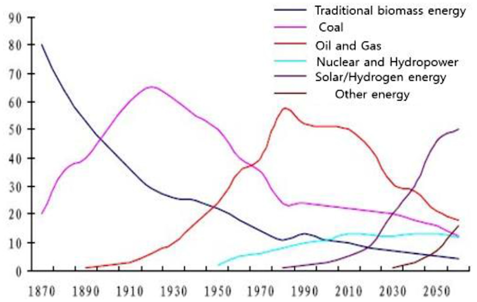
Global energy change trends.
One of the research problems is the risk caused by the increased temperature during the fast filling of hydrogen cylinders. 9 During the filling of compressed hydrogen, the temperature in the cylinder increased significantly, which may lead to low content of hydrogen. In order to avoid the risk that caused by temperature rise, it is necessary to study the thermal effect of the rapid filling process of the hydrogen storage tank. Under different fast filling conditions, experiments need to be carried out to determine the final temperature in the hydrogen tank and the mass of hydrogen that has been inflated.
In this paper, a thermodynamic model is established based on the hydrogen fast charging process. The theoretical analysis is used to quantitatively determine the temperature, mass, and filling time in the fast filling process. The laws of conservation of mass and energy are combined with the equation of real gas state to derive the expression of temperature in the hydrogen storage tank. The physical properties of hydrogen obtained by the software REFPROP9.5 combined with the experimental data and the results obtained by the numerical analysis method are compared to verify the accuracy of the temperature expression.
Hydrogen charging modeling inside the high pressure vessel
System analysis
Figure 2 shows the overall system structure of the experiment. 10 At present, the hydrogen compression system is to recycle the hydrogen compressed by a compressor at high pressure and stored in a high pressure container. After the hydrogen gas was discharged from the hydrogen storage tank car and compressed by a two-stage compressor, the compressed hydrogen gas passes through the heat exchanger and stores the low temperature and high pressure hydrogen gas in the high pressure tank (1) and the buffer tank (2); after the hydrogen was consumed, the system repeats the above process.

System structure of hydrogen tank.
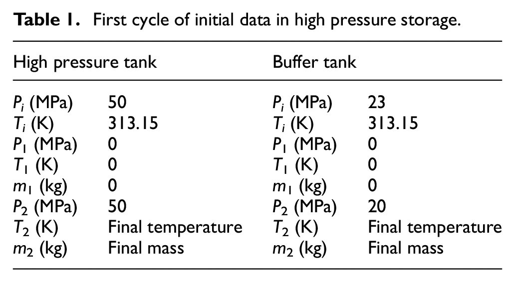
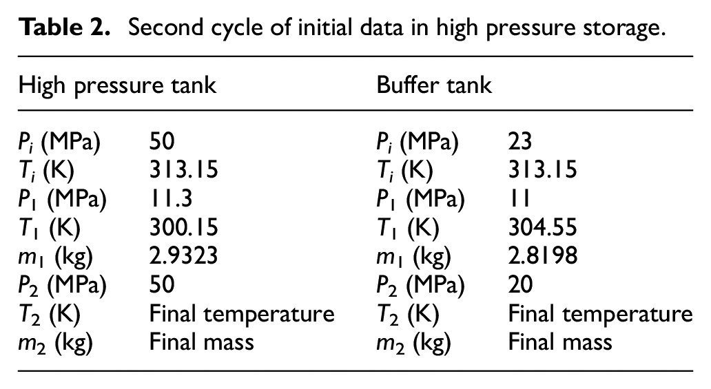
Tables 1 and 2 show initial data in high pressure storage. Pi and Ti are the pressure and temperature flowing into the high pressure vessel, P1, T1, m1 are the initial pressure, temperature, and mass in the high pressure vessel, P2, T2, m2 are the pressure, temperature, and mass in the high pressure tank after hydrogen filling process completed.
First cycle of initial data in high pressure storage.
Second cycle of initial data in high pressure storage.
Mathematical model and analysis
Figure 3 shows the changes in temperature, pressure and mass in the tank when hydrogen was filled into the high pressure tank and the buffer tank in the entire fast filling system.

Simple diagram of hydrogen fast filling process.
The process of filling hydrogen in a high-pressure tank was the process of storing hydrogen that has passed through the compressor in the container. During this process, the temperature of hydrogen increases; making the following assumptions helps to further analyze the fast charging process. Figure 4 describes theoretical model of the fast filling process for a high-pressure hydrogen storage cylinder.
The initial state of the first cycle of the high pressure hydrogen storage tank is vacuum. The state of the second cycle is the fast charging process at an initial pressure of 11.3 MP. The kinetic energy and gravitational potential energy of hydrogen are ignored.
During the filling process, the natural convection heat transfer coefficient of the outer wall of the hydrogen bottle is constant, and the ambient temperature is constant, Tamb = 28.9°C.
The temperature of the hydrogen that flowing into the high-pressure vessel is constant.
The temperature of the hydrogen flowing into the high-pressure vessel is constant.
The material of the hydrogen cylinder is stainless steel, and the thermal conductivity of stainless steel is regarded as isotropic, and its thermal conductivity is considered to be constant; k = 16.3 W/m•K.
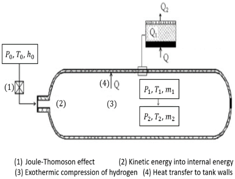
Theoretical model of the fast filling process for a high-pressure hydrogen storage cylinder.
The control equations of the model are described as follows 11 :
1. Mass conservation equation:

2. Energy conservation equation
3. Abel-Nobel Equation of state
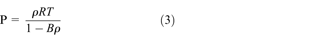
The present study used the Abel-Nobel equation of state for real gas model. In this equation, B = 0.007691 m3 for hydrogen gas. Compared with the NIST (REFPROP9.5) data, the results obtained from the equation (3) has a relative error no more than 4% in the range of 300 K < T < 410 K for high pressure gaseous hydrogen. 12
To monitor the temperature and pressure values inside the high-pressure hydrogen storage tank, the equations (1)–(3) must be solved at the same time, and the expression of the temperature in the hydrogen tank will be derived from the equations.
Theoretical results
Theoretical analysis
The analysis of the filling process in the state where the initial container is vacuum is called the “First cycle” analysis, and the analysis of the filling process in the state where the pressure remains in the container after the first cycle is called the “Second cycle” analysis.
In the fast filing process, the initial conditions of the theoretical analysis of the high pressure hydrogen storage tank are as follows: hydrogen is delivered to the tank through a compressor under high pressure compression, the flow rate of hydrogen is 0.008069 m3/s, the pressure is 50 MPa, and the temperature is 313.15 K. Figure 5 is schematic diagram of the simplified high pressure vessel model. Table 2 is the corresponding physical parameters of the tank.
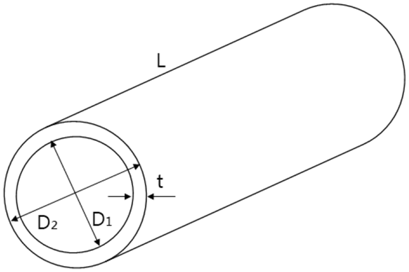
High pressure tank modeling.
The physical properties of hydrogen are obtained by the REFPROP 9.5 13 (NIST Reference Fluid Thermodynamic and Transport Properties Database: Version 9.5) developed by the NIST (National Institute of Standards and Technology), see Table 3 for high pressure tank specification and properties.
High pressure tank specification and properties.

The heat exchange model between the gas and the storage tank wall is a key parameter of the mathematical model, but the obtained heat transfer coefficient 14 needs to be close to the coefficient of the actual filling process. Bourgeois et al. 15 developed a heat transfer correlation for actual filling process as follow:
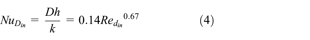
Scope of application of Reynolds number and Rayleigh number:


First cycle analysis
The pressure and temperature entering the high pressure hydrogen storage tank through the compressor and the heat exchanger are 50 MPa and 313.13 K. The initial state of the first cycle process is vacuum. When the hydrogen is charged under adiabatic condition, the temperature equation in the tank was derived by the conservation of mass equation and conservation of energy equation as follows.
Figure 4 shows the present filling process model:
where

By using the Abel-Nobel equation of state

In the process of the first cycle process, the initial state is vacuum, and the heat transferring to ambient is ignored (Q = 0), equation (7) can be simplified as follow:
Thermodynamic parameters
The heat transfer of the high-pressure hydrogen storage tank is shown in Figure 6. The model of heat transfer is mainly conduction and convection. Because the difference between the surface of the tank and the outside is relatively small, radiant heat transfer is ignored. 16


Difference between the inner and outer wall temperatures of the vessel.
In equation (9),
The overall rate of heat transfer calculated by equation (9) is 20 kW. During the filling process, the average heat transfer rate is assumed to be one half of the initial heat transfer rate;

The temperatures of the inner and outer walls of the high-pressure hydrogen storage tank were calculated based on equation (10), where
According to equation (10), the inner and outer surface temperature of the high pressure tank is
The method used to calculate the parameters in the buffer tank is the same as that used in the high pressure tank, and the results of the first cycle process are summarized in Table 4.
First cycle results of high pressure tank and buffer tank.

Second cycle analysis
When the fast filling process of the first cycle is completed, the pressures in the high pressure tank and the buffer tank are 11.3 MPa and 11 MPa. Then, hydrogen is continuously filled into the high pressure tank and the buffer tank through the compressor and heat exchanger, which is called fast charging process of the second cycle.
The temperature equation in the tank was derived by the conservation of mass equation and conservation of energy equation as equation (7).

In the process of fast filling, if the heat transferring to ambient is ignored (Q = 0). Equation (7) can be simplified as:

Also, equation (11) can be rearranged as follows:
Using experimental and simulated data 17 to verify the accuracy of the empirical formula of temperature rise, the results obtained from the equation has a relative error no more than 0.25%.
The mass of the hydrogen charge is obtained based on the temperature in the hydrogen storage tank calculated by the derived equation (12), see Figure 7 for final temperature of the reference (17) and the calculation result.

Final temperature of the reference (17) and the calculation result.
The method of evaluating
Second cycle results of high pressure tank and buffer tank.

Experiment analysis
The experiment was conducted by two-stage compression of the hydrogen contained in the tube trailer. After passing through the heat exchanger, the hydrogen was first stored in a high pressure tank and then stored in a buffer tank. After hydrogen was stored in each tank, the experiment was conducted by lowering its pressure through a pressure reducing valve and then a series of processes were repeated.
Figures 8 to 10 are a two-stage compressor and a high pressure vessel used in the experiment, Figure 10 is the sensor for measuring of hydrogen pressure in the tank. The pressure was controlled by pressure transmitter (P601 series), the error of the sensor is ±0.25%.

Hydrogen compression testing device.
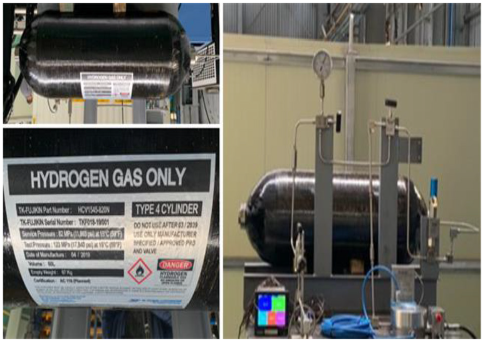
High pressure vessel for hydrogen storage.

Hydrogen pressure measuring sensor.
Figure 11 shows the rise in gas pressure and temperature over time. Figure 11(a) and (b) shows the experimental results of pressure measurement. Figure 11(c) and (d) are the corresponding temperature valuations by using the real gas equation of state. The maximum temperature in the tank grows rapidly at the onset of fast filling, and then the increase slows down, with a steady temperature near the end of filling process. This is because the fast filling process in the latter, the mass flow is small, and the heat absorption power of the stainless steel wall is greater than the temperature effect during filling.

Temperatures and pressures varying over time: (a) pressure curve for the first cycle, (b) pressure curve for the second cycle, (c) temperature in high pressure tank for the second cycle, and (d) temperature in buffer tank for the second cycle.
Table 6 describes comparison of final temperatures of the hydrogen between adiabatic and non-adiabatic filling processes. As a result of the analysis, based on the first cycle analysis of high pressure tank, the final temperatures were calculated to be 442.11 K for the adiabatic filling process, and 422.37 K for the non-adiabatic process. Based on the first cycle analysis of buffer tank, the final temperature were calculated to be 444.17 K for the adiabatic filling process, and 428.82 K for the non-adiabatic process. Based on the second cycle analysis of high pressure tank, the final temperatures were obtained as 397.12 K and 380.8 K for the adiabatic and non-adiabatic processes, respectively. For the second cycle of buffer tank, the final temperatures were 351.91 K and 344.81 K for the adiabatic and non-adiabatic processes, respectively.
Comparison of final temperatures of the hydrogen between adiabatic and non-adiabatic filling processes.

Based on the first cycle analysis of high pressure tank, the final mass values were calculated to be 7.705 kg for the adiabatic filling process, and 8.026 kg for the non-adiabatic process. Based on the first cycle analysis of buffer tank, the final mass values were calculated to be 3.4429 kg for the adiabatic filling process, and 3.5614 kg for the non-adiabatic process. Based on the second cycle analysis of high pressure tank, the changes of mass were obtained as 5.48 kg and 5.81 kg for the adiabatic and non-adiabatic processes, respectively. For the second cycle of buffer tank, the changes of mass were 1.45 kg and 1.54 kg for the adiabatic and non-adiabatic processes, respectively.
Conclusion
During the fast filling process, the gas temperature in the cylinder is gradually increased, the temperature distribution within the hydrogen tank has attracted a lot of attention. This study established a mathematical model for the temperature rise in the hydrogen fast filing system under targeted pressure. In addition, thermodynamic theory and software REFPROP 9.5 were combined to predict the temperature change in the hydrogen storage tank, the final temperature of hydrogen in the tank was calculated from the real gas equation of state, mass and energy conservation equations, which was compared with the experimental data. The experimental results are in good agreement with the theoretical results. The results of this study will be very useful in future hydrogen energy research and hydrogen station development.
The simple formula obtained from the analytical solution presented in this paper can be used to fit experimental or simulated data of final gas temperatures in the tanks with physically meaningful parameters, which can be applied for calculating the maximum temperature and for an effective controlling of the tank temperature during the fast filling process in the hydrogen stations.
The simple formula gives the relationship of the final hydrogen temperature with the initial and settled pressure in the tank, the temperature of inlet gas and the initial temperature in the tank.
At the same initial temperature, the higher the inlet temperature, the higher the final temperature in the tank. At the same inlet temperature, the higher the initial temperature, the higher the final temperature in the tank.
The mass values calculated from the theoretical non-adiabatic condition were higher than those from the theoretical adiabatic condition by 3.5%.
The theoretical calculation was based on the experimentally measured pressure value. The temperatures calculated from the theoretical non-adiabatic condition results were lower than those from the theoretical adiabatic condition by 5%.
In summary, the results of this study can provide a reference in terms of controlling the actual temperature in the hydrogen storage tank during the fast filling process and improving safety.
Supplemental Material
sj-zip-1-ade-10.1177_1687814020971920 – Supplemental material for A theoretical analysis of temperature rise of hydrogen in high-pressure storage cylinder during fast filling process
Supplemental material, sj-zip-1-ade-10.1177_1687814020971920 for A theoretical analysis of temperature rise of hydrogen in high-pressure storage cylinder during fast filling process by Ji-Qiang LI, No-Seuk Myoung, Jeong-Tae Kwon, Seon-Jun Jang, Taeckhong Lee and Yong-Hun Lee in Advances in Mechanical Engineering
Footnotes
Appendix 1
Handling Editor: James Baldwin
Author contributions
Conceptualization, J.-T.K. and S.-J.J.; methodology, J.-T.K.; software, J.-Q.L.; validation, S.-J.J., J.-Q.L.; formal analysis, J.-Q.L.; investigation, J.-T.K.; resources, J.-Q.L.; data curation, J.-Q.L.; writing—original draft preparation, J.-Q.L.; writing—review and editing, J.-Q.L.; visualization, N.-S.M.; supervision, N.-S.M.; project administration, T.L.; funding acquisition, T.L. and Y.-H.L. All authors have read and agreed to the published version of the manuscript. The authors declare no conflict of interest.
Declaration of conflicting interests
The author(s) declared no potential conflicts of interest with respect to the research, authorship, and/or publication of this article
Funding
The author(s) disclosed receipt of the following financial support for the research, authorship, and/or publication of this article: This study was a research project conducted by the Ministry of Trade, Industry and Energy and supported by the Korea Energy Technology Evaluation Institute (KETEP) as an energy technology development project (Nos. 2017301004183 and 20183010041940).
References
Supplementary Material
Please find the following supplemental material available below.
For Open Access articles published under a Creative Commons License, all supplemental material carries the same license as the article it is associated with.
For non-Open Access articles published, all supplemental material carries a non-exclusive license, and permission requests for re-use of supplemental material or any part of supplemental material shall be sent directly to the copyright owner as specified in the copyright notice associated with the article.