
Abstract
A novel shell-and-tube heat exchanger with screw cinquefoil orifice baffles is designed to grasp the weakness of the traditional shell-and-tube heat exchanger with cinquefoil orifice baffles. It specifically enhances the heat transfer coefficient in the area between adjacent baffles and enhances the shell-side fluid flushing ability on bundles. In the proposed shell-and-tube heat exchanger with screw cinquefoil orifice baffles, screw-type cinquefoil orifice baffles are installed in the shell side. Shell-and-tube heat exchanger with screw cinquefoil orifice baffle is compared with shell-and-tube heat exchanger with cinquefoil orifice baffles and the traditional shell-and-tube heat exchanger with segmental baffles by means of numerical simulations. The numerical result shows that the heat transfer coefficient and shell-side fluid flushing ability in the shell-and-tube heat exchanger with screw cinquefoil orifice baffle is higher than that in the shell-and-tube heat exchanger with cinquefoil orifice baffles and shell-and-tube heat exchanger with segmental baffles, for the shell-side fluid that is urged to flow in approximately continuous helical flow. Under the same shell-side mass flow rate, heat transfer coefficient of shell-and-tube heat exchanger with screw cinquefoil orifice baffle is about 9.2% higher than that of shell-and-tube heat exchanger with cinquefoil orifice baffles and shell-and-tube heat exchanger with segmental baffles by about 5.4% on average. The article presents a novel design thought when researchers design heat exchangers.
Keywords
Introduction
Shell-and-tube heat exchangers (STHXs) have been widely used in the chemical engineering, aviation industry, and so on for their wide range of allowable design pressures and temperatures. 1 However, shell-and-tube heat exchanger with segmental baffles (STHX-SG), the most widely used, has many disadvantages. For example, the shell-side fluid in STHX-SG flows across tube bundles in a zigzag manner, which could lead to a great flow resistance and a high vibration level. Other issues like the “dead” flow region and fouling, which cause low heat transfer efficiency,2–4 also trouble such heat exchanger users. To change this situation, many novel STHXs have been proposed.
The STHX with orifice baffles was originally proposed by Phillips Petroleum Company, 5 which has been widely used as heat exchanger for steam generator of nuclear power plants.6,7 In the STHX with orifice baffles, orifice plates have been developed as a support to tubes, and the shell-side fluid flows longitudinally through the gaps between the orifice edges and tube walls. This heat exchanger not only has a lower pressure drop, but also being less liable to fouls, eliminates stagnant recirculation zones and avoids flow-induced vibration compared to the conventional STHX-SG.6,8 Because of these advantages, the STHX with orifice baffles attracted considerable attention in recent years.
A El Maakoul et al. 1 using computational fluid dynamics (CFD) to simulated three STHXs with the recently developed trefoil-hole, helical baffles, and the conventional segmental baffles, respectively, at low shell-side flow rates. And the results indicated that helical baffles result in higher thermo-hydraulic performance while trefoil-hole baffles have a higher heat transfer performance with large pressure drop compared to segmental baffles. Y You et al. 6 based on the experimental results found that trefoil-hole baffles could generate high-speed flush, intensive recirculation flow, and high turbulence intensity level, which lead the Nusselt number of the shell side is about 4.5 times than without baffles. Y You et al. 8 studied the effect of baffle number and baffle distance on the small-size heat exchanger with trefoil-hole baffles. The convection heat transfer coefficient on the shell side of the small-size heat exchanger monotonically drops while the shell side overall thermo-hydraulic performance monotonically rises. There are many types of orifice baffles, such as trefoil-hole baffles, quatrefoil-hole baffles, and cinquefoil orifice baffles, but very few related academic literature are available. 6 Figure 1 depicts the sketch of some familiar orifice baffles. And the shell-and-tube heat exchanger with cinquefoil orifice baffles (STHX-COB) was the choice for further study.
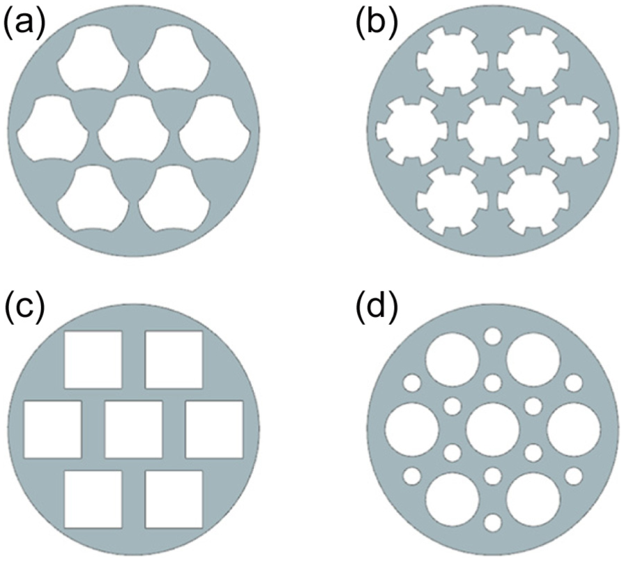
The sketch of some familiar orifice baffles: (a) trefoil-hole baffle, (b) cinquefoil orifice baffle, (c) rectangular orifice baffle, and (d) small round hole orifice baffle.
However, the enhanced heat transfer region in STHX-COB is focused on the vicinity of cinquefoil orifice baffles. The heat transfer performance in the area between adjacent baffles is still not satisfactory. Although there appear various types of orifice baffles in recent years, design of new shapes of the orifice attracts research interests. The aforementioned problem has not been resolved, which limits the development of STHX-COB.
While the shell-and-tube heat exchanger with helical baffles (STHX-HB) shows good thermo-hydraulic performance and low vibration level. 9 STHX-HB was first proposed by Lutcha and Nemcansky. 10 They proposed the helical baffles in STHX-HB are the most important factor influencing heat transfer, which directly leads to the shell-side fluid to flow in approximately continuous helical flow. And they found that the helical baffles could force the shell-side fluid to approach plug flow, which increased the average temperature driving force. The flow patterns induced by the baffles also intensified the shell-side heat transfer remarkably. 11 Generally speaking, there are two kinds of helical baffles, continuous helical baffles and discontinuous helical baffles. Considering the difficulty in the manufacture of continuous helical baffles, the discontinuous helical baffles formed by overlapped fans or oval-shaped plates to replace it now. But the leakage by discontinuous helical baffle is relatively large due to the triangle zones, which will reduce the heat transfer performance. 12 S Wang et al. 11 proposed folded helical baffles which can block the triangle leakage zones between two adjacent plain baffles in STHX-HB. And the experimental results showed that the integrative performance of STHX-HB is greatly enhanced by the improved folded baffles.
To solve above problems, through using STHX-COB as the foundation, introducing the concept of the helical flow in STHX-HB, a new type of heat exchanger, shell-and-tube heat exchanger with screw cinquefoil orifice baffles (STHX-SCOB), was proposed. STHX-SCOB provides a new choice for industry. In this article, STHX-SCOB was simulated by CFD method. The shell-side flow patterns of STHX-SG, STHX-SCOB, and STHX-COB were compared numerically. Moreover, impacts from two significant parameters, including the helical angle and baffle thickness, on the heat transfer and pressure drop performance of STHX-SCOB, were studied.
Mathematical modeling of the shell-side flow field
Physical models
The physical model of STHX-SG is presented in Figure 2(a) and (d). In STHX-SG, the baffle thickness is 3 mm, and the baffle cut is 36%. The baffle number is 4. And the baffle pitch is 117 mm. More details are listed in Table 1.
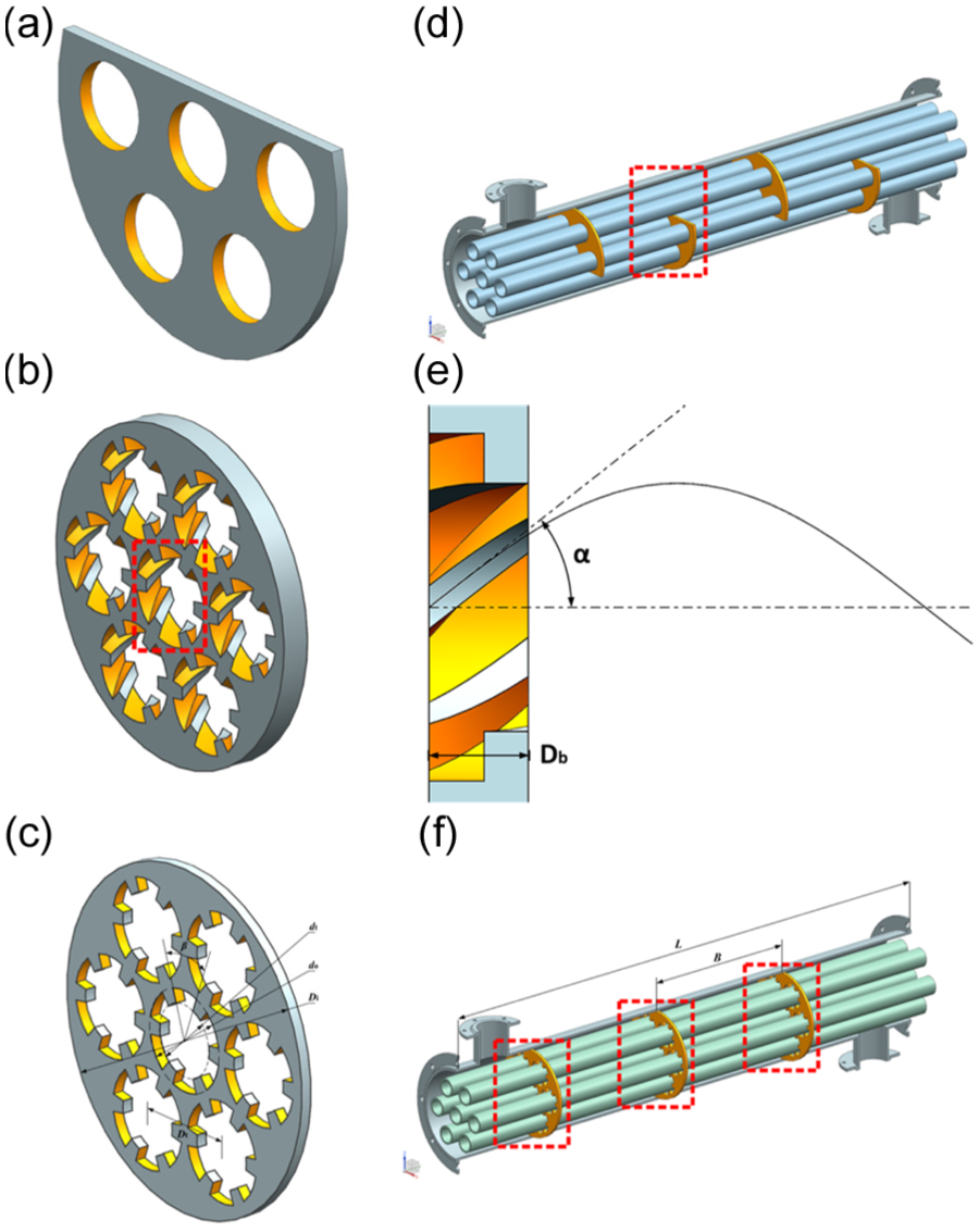
The shape of three heat exchangers: (a) graphical model of segmental baffle in STHX-SG, (b) graphical model of screw-type cinquefoil orifice baffle, (c) graphical model of cinquefoil orifice baffle, (d) graphical model of original tube bundle in STHX-SG, (e) two significant parameters which influent heat transfers performance in STHX-SCOB, and (f) graphical model of original tube bundle in STHX-COB.
Common geometry parameters for three models.

In STHX-SCOB, screw-type cinquefoil orifice baffles are substituted for plain baffles to be installed in the shell side. The original straight flow path was replaced by helical flow path. The shapes of two kinds of baffles are shown in Figure 2(b) and (c), respectively.
As shown in Figure 2(e), the helical angle α refers the angle between the central axis and the channel line tangent. In this figure, α at 38° and the baffle thickness with
To simplify numerical simulation while still keep the basic characteristics of the process, following assumptions are made:
The fluid-flow and heat transfer processes are turbulent and in steady state;
The leak flows between baffle and the shell are neglected;
The tube wall temperatures are kept constant in the whole shell side;
The natural convection induced by the fluid density variation is neglected;
The heat exchanger is assumed well insulated, and the heat loss to the environment is totally neglected. 8
Governing equations and boundary conditions
The renormalization group (RNG) k-ε model of Yakhot and Orszag is adopted in the simulation because the model provides improved predictions of near-wall flows and be chosen by many researchers. 13 The RNG k-ε model was derived by a statistical technique called renormalization method, which is widely used in industrial flow and heat transfer because of its economy and accuracy. 14 The governing equations for continuity, momentum, energy, k, and ε in the computational domain can be expressed as follows:
Continuity equation

Momentum equation

Energy equation

Turbulent kinetic energy equation

Turbulent dissipation energy equation

where

The empirical constants for the RNG k-ε model are assigned the following values


The shell-side inlet pipe is set as velocity inlet, while outlet pipe is set as pressure outlet. Water is used as the working fluid, and its thermal properties depend on its operation temperature. The temperature of inlet is 360 K and the pressure of outlet is 0 atm. The reference pressure is 1 atm. The wall temperatures of the tubes are uniform and fixed to 300 K. Other shell walls are non-slip, impermeable, and adiabatic. The computer code CFX is used to simulate the flow and heat transfer. The governing equations are iteratively solved by the finite-volume method with semi-implicit method for pressure-linked equations (SIMPLE) pressure–velocity coupling algorithm. The advection scheme chose high resolution for calculation. The convergence criterion is that the normalized residuals are less than
Data reduction
Shell-side velocity and Reynolds number
The mean shell-side fluid velocity is defined by


Here,
With the mean velocity value, the Reynolds number for the shell side is determined by

where

About STHX-SCOB and STHX-COB, the following expression is used to calculate Reynolds number
N is the tube number.
Heat transfer rate and overall heat transfer coefficient
Heat transfer rate of the shell-side fluid is determined by

In above equations, m is the shell-side mass flow rate,


Nusselt number, friction coefficient, and comprehensive performance

In above equations, B is baffle pitch,
Model validation
Grid generation and independence
The three-dimensional (3D) geometry was created in unigraphics next generation, which next meshed by tetrahedral and hexahedral grids in the commercial code integrated computer engineering and manufacturing code for computational fluid dynamics (ICEM). Because ICEM has excellent merit on managing very complex 3D geometries (see Figure 3). According to Zhu et al., 18 the same method that the tetrahedral mesh was used in the region near to the cinquefoil orifice baffles and the hexahedral mesh is used in the region outside of the cinquefoil orifice baffles is applied in the research, and the simulation results by this method coincide well with the experimental results.

Meshes of computational model: (a) meshes of STHX-COB and (b) meshes of STHX-SCOB (α = 38º, Db = 8 mm).
For make sure the accuracy of simulations, according to Wang et al. 12 and Yang et al., 19 the grid independence of the numerical solutions was conducted on STHX-SCOB, STHX-COB, and STHX-SG.
Four different grid systems are generated for the STHX-SCOB (α = 38°, Db = 8 mm, m = 0.375 kg/s) and their results are shown in Figure 4. Under the operation conditions of G3 and G4, differences of

STHX-SCOB results of different grid systems (α = 38º, Db = 8 mm, m = 0.375 kg/s).
Numerical investigations compared with other papers
The verified STHX-SG model geometry was made exactly as Ozden and Tari 20 and MG Yehia et al. 21 for it is similar to the STHXs being studied in this article. The verified STHX-SG baffle number is 6, and the baffle cut ratio is 36%, while other model geometrical parameters are presented in Ozden and Tari 20 and Yehia et al. 21 According to the literature value, water is the working fluid. The shell inlet temperature is 300 K, and tube wall temperature is 450 K. The shell outlet is pressure outlet.
While the turbulence model is RNG k-ε model, and pressure–velocity coupling is SIMPLE. The CFD package CFX is used to simulation. After grid independency check, the number of cells is 2,841,973.
Figure 5 shows the simulation results by the method in this article compared with the results in Ozden and Tari.
20
In addition, the results in Ozden and Tari
20
are considered satisfactory by MG Yehia et al.
21
The maximum relative deviation for heat transfer coefficient h is 5%, and the shell-side pressure drop

The comparison between the result in Ozden and Tari 20 and the simulation result by the proposed method: (a) variation of h with tube side inlet flow rate m in comparison with Ozden and Tari and the results by the proposed method and (b) variation of Δp with tube side inlet flow rate m in comparison with Ozden and Tari and the results by the proposed method.
Results and discussion
Flow distributions in different heat exchangers
The flow behavior in STHX-SG is shown in Figure 6. The streamline pattern in shell side is a zigzag pattern, which causes large dead zones. The region back of the baffles has eddy formation and fluid recirculation, causing a large amount of energy spent in this region.

(a) Flow distributions in STHX-SG (m = 0.375 kg/s) and (b) local magnification in STHX-SG.
The flow distributions in shell side of STHX-SCOB and STHX-COB are totally different. Figure 7 shows the distribution of flow lines in shell-side velocity flow field of these two heat exchangers when the shell-side mass flow rate m is 0.375 kg/s. As shown in Figure 7, due to the sudden decrease in flow passage area at baffles, the shell fluid velocity increases, which results in jet effect and destruction to the boundary layer in two heat exchangers. Besides, in Figure 7(c), the secondary flow can be found in local enlarging graph, which disturbs the shell fluid and enhances the heat transfer. While in Figure 7(b), due to the effect of the helical angle, the tube bundles are washed out by revolving fluid. As shown in Figure 8(b), the shell flow velocity in STHX-SCOB is higher, especially in peripheral side tubes’ wall. The spiral motion brings about good mixing, which directly leads to improvement of heat transfer. Moreover, a higher flow velocity enhances the shell-side fluid flushing ability. The new type of heat exchanger is more like helical baffle heat exchanger in some way.

Flow distributions in different heat exchangers (m = 0.375 kg/s): (a) flow distributions in STHX-COB, (b) flow distributions in STHX-SCOB (α = 38º, Db = 8 mm), (c) local magnification in STHX-COB, and (d) local magnification in STHX-SCOB (α = 38º, Db = 8 mm).

Velocity contours in different heat exchangers (m = 0.375 kg/s, Z = 200 mm): (a) velocity contours in STHX-COB and (b) velocity contours in STHX-SCOB.
Heat transfer coefficient
Heat transfer coefficient h is a very significant parameter in design of industrial STHXs because it is related to the area of land occupied by the equipment and the cost of production materials. Therefore, h is obtained more attention in some cases.
Figure 9 illustrates relationship between h and m. In Figure 9, h of STHX-SCOB is obviously higher than that of STHX-COB by about 9.2% and STHX-SG by about 5.4% on average. With m of 0.15 kg/s, h in the STHX-SCOB is higher than that of the STHX-COB by 15.4%; but when m increases to 1.5 kg/s, the difference drops down to 6.9%. The reason for this phenomenon is that in STHX-SCOB turbulence is stronger than STHX-SG and STHX-COB, which leads to a higher heat transfer coefficient, particularly at low m.
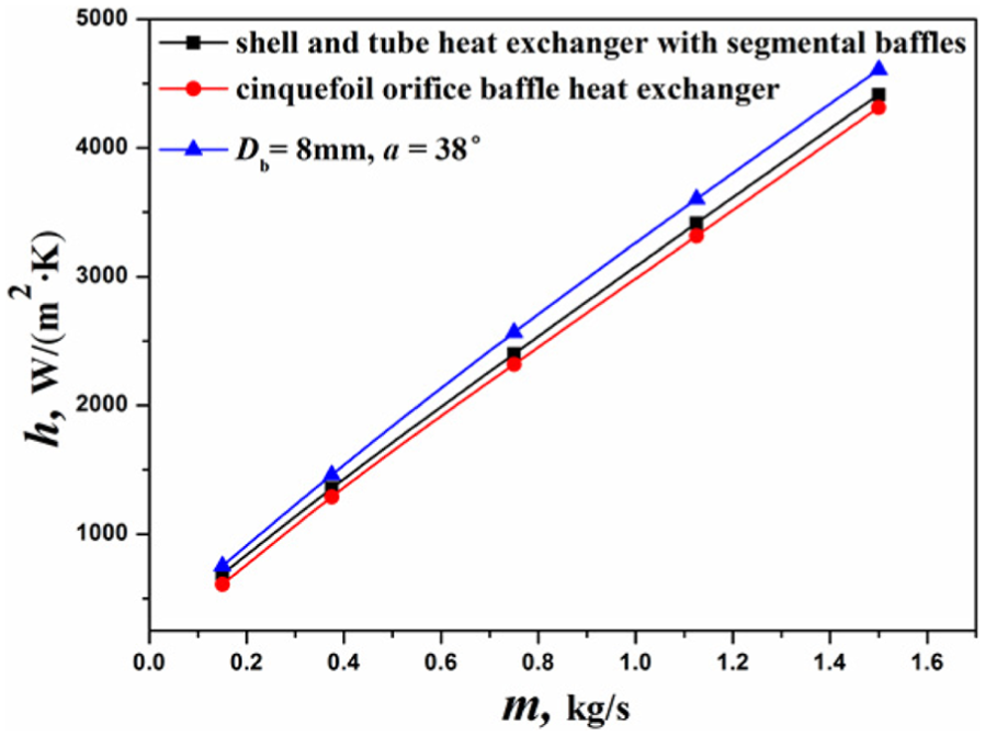
Heat transfer coefficient versus the shell-side mass flow rate.
Pressure drop and comprehensive performance
The relationship between the shell-side pressure drop

Other heat transfer performances: (a) pressure drop versus the shell-side mass flow rate and (b) comprehensive performance versus the shell-side Reynolds number.
But the pressure drop is not the only standard to judge the performance of the heat exchanger. Comprehensive performance,
Effects of structural parameters on STHX-SCOB
The helical angle of helical flow paths
According to the design thought about helical baffle heat exchanger,22,23 the helical angle α impacts heat transfer and flow characteristics of the STHX-SCOB significantly. STHX-SCOB with different helical angles (α = 27°, 38°, and 46°) was studied. As shown in Figure 11, h and

Heat transfer performances with different helical angles: (a) velocity flow distribution (α = 27º, m = 0.375 kg/s, Db = 8 mm), (b) velocity flow distribution (α = 38º, m = 0.375 kg/s, Db = 8 mm), (c) velocity flow distribution (α = 46º, m = 0.375 kg/s, Db = 8 mm), (d) heat transfer coefficient versus the shell-side mass flow rate, (e) pressure drop versus the shell-side mass flow rate, and (f) comprehensive performance versus the shell-side Reynolds number.
Above phenomenon can be explained that the shell fluid radial velocity increases after flowing through helical flow paths. The bigger the α gets, the bigger the shell fluid radial velocity becomes. However, the axial velocity of shell fluid is small at high α. Therefore, it brings about good mixing, which directly leads to the strong heat transfer. However, the energy loss is big.
The baffle thickness
Due to the novel baffle changes the shell fluid distribution, both h and

Heat transfer performances with different baffle thicknesses: (a) temperature flow distribution (Db = 3 mm, m = 0.375 kg/s, α = 46º), (b) temperature flow distribution (Db = 8 mm, m = 0.375 kg/s, α = 46º), (c) temperature flow distribution (Db = 13 mm, m = 0.375 kg/s, α = 46º), (d) heat transfer coefficient versus the shell-side mass flow rate, (e) pressure drop versus the shell-side mass flow rate, and (f) comprehensive performance versus the shell-side Reynolds number.
From Figure 12(d), h in the STHX-SCOB with
Conclusion
In this article, a novel STHX-SCOB with helical flow paths is proposed to improve heat transfer performance at shell side. When the traditional STHX-COB and STHX-SG are compared, considering the impacts from the structure parameters of screw-type cinquefoil orifice baffle, heat transfer and pressure drop performance at shell side is investigated, and the most significant conclusions are summarized as follows:
As a novel heat exchanger, STHX-SCOB provides a new heat transfer enhancement choice. Besides, the screw structure in the STHX-SCOB improves fluid flushing ability on the shell side. The screw-type cinquefoil orifice baffles enhance the heat transfer considerably, and this enhancement is done at the expense of a large pressure drop. So next, other screw-type orifice baffle heat exchangers should be researched to obtain the optimal structure parameters for other screw-type orifice baffle heat exchanger.
Under the same shell-side mass flow rate m, heat transfer coefficient h of STHX-SCOB is about 9.2% higher than that of STHX-COB and STHX-SG by about 5.4% on average, while the pressure drop
Under the same shell-side mass flow rate m and
Under the same shell-side mass flow rate m and α at 46°, the bigger the
Footnotes
Appendix 1
Academic Editor: Oronzio Manca
Declaration of conflicting interests
The author(s) declared no potential conflicts of interest with respect to the research, authorship, and/or publication of this article.
Funding
The author(s) disclosed receipt of the following financial support for the research, authorship, and/or publication of this article: This work was supported by the Program of National Natural Science Foundation of China (No. 51506090).