
Abstract
Fused Deposition Modeling (FDM) is an extrusion type additive manufacturing (AM) method in which a molten polymer is selectively extruded in layer-by-layer manner. Although there are several other AM techniques, FDM is a suitable method to produce fabric structures as it is capable of processing polymers and is widely used in various engineering applications. This article summarizes the current research works in characterization of FDM parts, advancements in materials used in FDM and latest works related to making fabric samples using FDM. The results show that the mechanical properties and surface quality are compromised in FDM parts. Strength and flexibility with better surface finishing are essential parameters in fabric structures. There are mainly two techniques that are explored by researchers to enhance the quality of the parts. The first is optimizing process parameters and the second is improving material quality. FDM process parameters like extrusion temperature, layer height, print speed and built orientation can significantly influence the quality of the parts. Optimizing these parameters can significantly enhance the strength of the fabric produced. Moreover, a great amount of impetus is given to improve material by reinforcing it and making polymer blends with specific qualities. There has been studies related to the development of fabric structures and deposition of polymers on fabrics with FDM. It is concluded that the major concern with such structures is strength and processability. To address these issues, optimizing process parameters and developing new filaments for exclusively making fabrics can be the future work in this area.
Keywords
Introduction to additive manufacturing
The term 3D printing normally indicates the development of a 3-dimensional shape product beginning with a 2-dimensional layer, which is also known as additive manufacturing (AM) because material is added together according to a design unlike in the traditional subtractive manufacturing in which material is removed from the initial raw structure. Scientists and researchers have referred to this manufacturing method as additive layered manufacturing because the material is produced by joining one layer on top of another adjacent layer. During the nascent period of this technology, most of the applications were in rapid prototyping. Hence AM is also called rapid manufacturing in some of the earlier literature.1–3 The ISO/ASTM 52900 standard defines additive manufacturing in broader perspective as a group of various technology which follow the principle of joining materials together as specified by a particular 3D design to create a physical object. 4
Modern additive manufacturing started with stereolithography (SL) technology which was initiated with processing of a polymer (hardening) selectively in layer-by-layer fashion. The powder and laser beam technology was later introduced. 5 The first AM machine was developed in 1984 by Charles W. Hull under the 3-D system corporation named Stereolithography Apparatus. 1 The Stereolithography and laser techniques along with fused deposition modeling techniques were commercialized in the late ‘80s and ‘90s. 5 In the early days, AM technology could not develop properly because it used to be an expensive technology. However, after the major patent expired in 2009, this technology saw new developments and the application of it has been broadening to newer fields. 6 The cost of technology has also come down. Typical desktop AM machines are now available for just a few hundred dollars. The AM industry has been growing fast and now it is a multi-billion dollar industry. 1
Irrespective of the manufacturing process, all the AM methods follow the data given by 3D CAD designed solid model. Firstly, a solid CAD model is made replicating the final desired object to be produced. The CAD design is then subjected to slicing software which slices the CAD model into many layers with a constant height as specified by the user. The slicing software also generates digital codes, known as G-Code, containing toolpath depending upon the user inputs like speed, layer height and manufacturing angle.7,8 The digital code is then fed into the machine which follows the input tool path and produces the object joining each adjacent layer together.
5
Representative diagram for the AM process and workflow is shown in Figure 1. The working mechanism of a 3D printing or AM machine is no different than inkjet printers apart from the fact that 3 dimensional objects are produced in AM. Like the inkjet printer that prints a layer of a given shape on paper, AM machine prints material on a build plate step by step or layer by layer. However, thickness of each layer may vary depending on the solid design and toolpath provided.
1
Schematic diagram of additive manufacturing process flow.
The ability of processing a variety of materials like plastics, resins, rubbers, ceramics, glass, concrete, and metals makes AM popular among designers and engineers. 6 This technology, during its initial days of development, was used in rapid prototyping. The replication of final product, also called prototype model, is made with AM and tested before the mass production of the actual product. This saved a lot of time and resources. 1 Prototypes made with AM are also used to develop conceptual initial design for new products which is advantageous in many ways. 9 Other advantages of AM technology are rapidly explored by the scientific community resulting in employing this method for industry scale production as well.
One of the main design advantages of AM is its ability to produce complex geometric structures. The use of computer-based modeling of the final product gives the user more flexibility to incorporate intricate design into the part. This manufacturing technique greatly reduces the need for expensive tools to produce parts as the machine operates itself taking inputs directly from a computer. Another advantage is that the AM needs less manpower as compared to other traditional manufacturing techniques. The reduction in part design, production time, tool and manpower reduce the cost of the final product. 2 AM technology provides a new perspective of manufacturing in the form of on-site design, implying that there is a possibility of designing a product during the processing stage itself. This opens doors for customized design and the ability to produce personalized parts. This results in a wide application of AM in biomedical and pharmaceutical industry. A great example of this is personalized scaffolds for medical application10,11 and smart drug delivery systems. 12 Aircraft parts, space structures, and rockets might be complex in design but need not to be produced in bulk quantity. Such customized and complex parts can be easily produced with AM. Customized design and rapid production lead the industries towards on-demand and decentralized manufacturing which largely reduces the storage related costs. Since AM follows the principle of adding material layer by layer, it can reduce raw material up to 75 % and reduce carbon footprint of the production. AM reduces the environmental impact from manufacturing industry.5,13 Advantages like efficient use of resources, higher product life, shorter and simpler supply chain with localized production make AM applicable in rapid prototyping, production of spare parts, small volume manufacturing, machine tool manufacturing, rapid repair, health care and medical, aerospace, and automobile industries. 14 AM is finding its way in the construction field as well. The ability to make complex structures and designs in addition with reduced labor requirement makes AM popular among architectures and in construction industry. 15 The use of AM technique to produce flexible textile structures is also being explored by scientific society.16–18
Types of AM
Classification of additive manufacturing based on principle and material processing (original source ISO/ASTM 52900:2021), summarized from Godec et al. 20

In this review, short descriptions of some commercially popular methods are presented. A detailed description of various types of AM technology is reported in D. Godec et al. 2022.
Material extrusion method (mex)
Material extrusion method, also known as fused deposition method (FDM) or fused filament fabrication method (FFF) is one of the most popular AM methods where hot material is extruded through a nozzle to deposit on flat surface layer by layer. 20 Detail discussion is made about this method below.
Vat photopolymerization
In this method, a liquid photopolymer is selectively cured. Light of a defined wavelength is used to cure monomers or oligomers in liquid state to form thermoset structures.20–22
Stereolithography
In this method, a three-dimensional object is produced by cross linking of consecutive layers of photopolymer surface. A single layer of photopolymer, placed on curing substrate, is selectively treated with Helium Cadmium (He-Cd) or Argon (Ar) laser generated UV light scans. After solidifying the layer, the built platform is lowered for another layer and the process repeats for the next layer. After some recent developments, stereolithography can produce multicolor products as well. Major advantages of this process include speed, precision, high detail, and ability to work with complex structures. The layers are thin in this method and transparent objects can also be produced.20,23–26
Vat photopolymerization with digital light processing
In this method, photosensitive resin is selectively cured using digitally processed light signal. The desired cross section of the individual layer is represented in the projected light signal. A variety of photosensitive materials like epoxy and acrylic resin, nano composites, ceramic composites, photopolymer with wax content and biocompatible materials can be processed with this method. Dentistry, medicine, jewelry, and arts are some of the most common application areas of this method.20,27–29
Material jetting
PolyJet technology, which works on the principle of material jetting on a build platform is like photopolymerization process, but the final product of this method does not require post processing or curing because of relatively thinner layers. However, this process might need support structure depending upon the complexity of the geometry. The application of UV light is able to produce parts with up to 16 µm thick layers which is 1/5 of the thickness of the stereolithography layer.20,30,31
Sheet lamination
The sheet lamination method is applicable to metals and polymers. In this process, materials are placed together in the form of sheets as a bundle, and they are bonded together layer by layer according to the design provided to get a solid object.20,32 Sheets are consolidated together by either bonding, ultrasonic welding, or brazing method. The individual sheets are cut into desired shapes for that layer before bonding to the previous layer. However, the reverse process can also be done which is bonding the sheets before cutting to acquire the desired shape. For the post processing of the product, CNC machining or laser technology is used.33,34
Powder bed fusion
In the powder bed fusion method, thermal energy is used to selectively fuse certain regions of a powder bed. The possibility to process powder-based metal, polymer, and ceramic material into accurate three-dimensional objects in a quick and reliable manner has expanded AM applications to not only rapid prototyping but to other industrial and commercial applications as well. There are several different categories of powder bed fusion methods based on source of heat generation. For example, electron beam melting (EBM), also known as electron beam powder bed fusion of metals (PBF -EB/M), uses electron beam gun to produce power. Similarly, laser beam is used to produce heat in selective laser melting (SLM), laser beam powder bed fusion of metals (PBF-LB/M), selective laser sintering (SLS) and powder bed fusion of polymers (PBF-LP/P) methods. Additionally, UV light is used as power source in some methods like multi jet fusion (MJF) and powder bed fusion of polymers with infrared light (PBF-IRL/P) methods.20,34–36
Directed energy deposition
Directed Energy Deposition (DED), also known as laser engineered net shaping (LENS) or direct metal deposition (DMD), uses power sources like laser, electron beam or plasma arc to melt the material in a controlled way to deposit it in the desired shape. In this method, the material (mainly metals like copper, stainless steel, titanium, tin aluminum, nickel, and cobalt) is melted and at the same time is deposited according to the CAD model.34,37 Like every other method, process parameters, such as thermal energy or thermal gradient affect the quality of the DED product. Laser power, powder feed rate, travel speed, layer height and hatch spacing influence the thermal gradient resulting in property variation on final part quality. 38
Binder jetting
Binder jetting uses liquid bonding agent to selectively deposit material powder to provide 3D shape. This method can incorporate complex designs without any need for support structure and has high processing speed. The method can be used with a variety of materials like polymer, metal, sand, and ceramic.20,34,39
Comparison between fundamental AM methods.

Fused deposition modeling (FDM)
Fused deposition modeling is also referred to as fused filament fabrication. It is a hot melt extrusion process where layer by layer deposition of molten polymer filament takes place. The deposited molten material solidifies gradually to provide the desired solid object.40,41 FDM is a widely used additive manufacturing technique for processing thermoplastics. The ability to be processed in molten state makes many thermoplastics suitable for FDM. The processing steps for FDM are similar to other AM methods. The 3D design of the object is made with computer software (. stl format) and converted to G code using slicing software. G code includes information necessary to handle FDM process such as printing speed, temperature, layer height and printing angle. A typical FDM machine consists of an extruder motor, pulleys and belts, print bed and a fan. The motor feeds the filament into the extruder; pulley and belt move the extruder in 3 directions. A bed is usually made of glass and is equipped with a heating option. It holds the extruded material and support material. Some advanced FDM machines come with multiple extrusion nozzles. 42 The nozzle diameter plays an important role in production time and quality. A larger diameter reduces processing time and increases part quality. However, while operating with large nozzle diameter, geometrical accuracy might have to be compromised.43,44 The effect of process parameters on FDM parts will be discussed in later sections. FDM is a direct contact process hence the distance between the nozzle and deposition surface is an extremely important factor. There is not much discussion about this aspect of FDM in literature. The distance between the nozzle and bed should not be very high as material cannot hold onto the surface but should be sufficiently high to allow processing and smooth movement of the nozzle in order to deposit a variety of polymers. 45
Fused Deposition method can process a wide range of polymeric materials such as Polylactic Acid (PLA), Acrylonitrile Butadiene Styrene (ABS), Polyvinyl Alcohol, Thermoplastic Elastomer, Polycarbonate, Polyethylene Terephthalate Glycol, and other polymers.42,46 The polymer is fed into the machine in the form of continuous filament with uniform diameter, usually 1.75 mm or 2.85 mm, with the help of a stepper motor and gears for uninterrupted feed. 41 The diameter of the filament feed does not impact the properties of the product. However, they can have some sort of processing advantage over one another. A large diameter filament feed offers smooth feed and less chance of breaking or interruption in supply. On the other hand, smaller diameter size filament can be fed rapidly. 46 The type of polymer material influences the processing and properties of FDM parts printed. Molecular weight, crystallinity and intermolecular bonding determines the mechanical properties of a polymer which eventually reflects on printed part properties. Sometimes it is a wise solution to go for a different material with better mechanical properties rather than trying to improve the mechanical properties of the printed part. One should keep in mind the fact that not all polymers can be processed with FDM, 41 which is one of the drawbacks of this method.
Comparison of mechanical properties for injection molding and FDM of various polymers. 41

FDM of thermoplastic materials have a wide range of applications because of its unique features and ease to process a variety of plastic materials. In the early days, FDM was used widely in prototyping and tooling. However, continuous improvement of part mechanical properties and enhanced control of process parameters allowed this technology to be used to produce functional parts as well. Currently, FDM is used in medical, automotive and aeronautical industries.49,50 Scientists have employed FDM to manufacture functional parts in various areas. Foresti et al. used FDM process to manufacture masks to protect from viruses like COVID-19. They mentioned that there are plenty of factors to be considered while producing masks and respirators such as healthiness, breathability, safety, virus protection, and reusability. They reported that upon careful consideration of such factors along with the government guidelines, the respirators can be produced using FDM technique with several polymers such as PLA, polyolefin, and styrene ethyl butylene styrene. Moreover, FDM’s ability to produce unique design and customized products made it a potential manufacturing method for producing medical parts such as medical scaffolds and prostheses.10,51 In-site production with high efficiency, precision and cost effectiveness are a few requirements for medical and dental products. Looking into these factors, several researchers have shown that FDM can successfully meet these requirements for producing dental implants, bone mimicking scaffold and tissues for personalized applications.51–53
FDM has been explored by scientists to produce customized fabric structures and shoes. Adanur et al. have applied FDM technique to produce several designs of interlaced fabric structures. Similarly, Dominguez et al. have shown through their results that this method can be used to produce complex shoe heels. Important aspects like ergonomics, mechanical behavior and aesthetic view can be successfully handled through the control of process parameters of FDM.16,17,54 Moreover, another important application area of FDM is automotive and aeronautics. The ability to produce complex and weight-controlled parts makes FDM suitable in these areas. Researchers have successfully printed automotive and electronic parts of reduced weight without compromising performance.55–57
Effect of process parameters on surface roughness of FDM parts
The surface roughness in FDM parts is contributed by several factors. Roughness is caused by the slicing mechanism and thermomechanical aspect of the material. 58 The slicing mechanism is related to the representation of a physical object with a combination of triangles. However, this method is only an approximation technique to represent an object which leads to surface roughness. 59 A molten polymer is deposited on top of another surface. This process needs rapid cooling of the viscous material which causes unnecessary shrinkage and stress. The shrinkage of the part forms the undesired surface roughness which leads to higher post processing cost, bad aesthetics and limited functionality of the product. 58 The literature shows that most of the research work done related to the surface roughness of the FDM parts is focused on average roughness (Ra), which is evaluated based on process parameters like layer thickness, cross-sectional shape, surface angle, layer overlap, and build orientation.60–62 Some scientists have developed theoretical models to predict a roughness parameter for a range of deposition angles. In addition, neural network approach is also applied to theoretical models to predict roughness parameters for a wider range of deposition angles.63–65 The thermomechanical phenomenon behind surface roughness of FDM part is associated with two major bonding of semi-molten polymer materials on top of each other layer by layer. These two bond types are interlayer bonding and intralayer bonding which are influenced by thermal energy of the material and are critical for determining characteristics of the final part including surface roughness. 66 The staircase effect is the most prevalent reason for poor surface finish in FDM parts. Layer by layer appearance results in poor surface finish in addition with lower dimension precision and stress concentration on the part. Some other reasons for poor surface finish are chordal effect, residue of excess material, roughness due to support structure, and errors in starting and finishing of layers.66,67 These effects are induced in FDM parts due to various process parameters.
Effect of layer thickness
Findings of the previous studies related to the relationship of layer thickness with surface finishing of FDM parts contradict each other. Some work suggests that higher layer thickness results in better surface in FDM products because higher thickness increases amplitude and spacing which results in decreased stair-step effect.68,69 In contrast, Perez et al. have reported that layer height and wall thickness should be kept as low as possible for better surface finish for FDM parts of PLA. 70 The results of Mrowka et al. show that surface roughness of PLA and ABS FDM parts decreases as layer thickness decreases. Layer thickness of 0.06 mm and 0.1 mm resulted in lower surface roughness as compared to higher layer thickness ranging up to 0.4 mm in their study. 71
Effect of built orientation
Build orientation, also known as print orientation, usually depends upon the complexity of the FDM part design and influences the surface roughness of the final product. Past research work has shown that surface roughness is higher for higher build orientation angle. 72 Through experimental and simulation methods, Corral et al. studied surface roughness of PLA samples with a range of built orientation (5°–85°) and concluded that the roughness increases with increase in built orientation. They observed that regular surface profiles highlighted by round peaks and sharp valleys are observed at lower orientation whereas, the distance between neighboring peaks is found to be increasing in case of higher orientation angle leading to flatter gaps which eventually increases the roughness. 73
Effect of print speed
When a sample is manufactured with a higher printing speed in FDM process, there is a chance that material is not deposited correctly and there might be lesser time available for polymer chains to diffuse and crystallize. In addition, the material cannot be deposited homogeneously at higher print speeds. In contrast, lower speed of deposition allows polymer to solidify slowly and make bonds with wide side chains which results in better surface finish. 66 Along with layer height, the amount of material deposited, which is influenced by printing speed, has significant effect on surface topology of FDM parts. 74
Effect of extrusion temperature
Higher extrusion temperature reduces the viscosity of a polymer resulting in reduced surface roughness. When a polymer is extruded on top of another layer (or a bed for initial layer) through the nozzle, it gets deposited with a circular cross section. But, if the viscosity of a polymer melt is lower, it struggles to hold the circular shape and becomes elliptical cross section which offers more contact area with bed or previous layer as compared to circular cross section. This results in a better surface finish.
66
The oval cross sections of a polymer melt also reduce surface roughness by reducing the height of peak and valley on the surface as illustrated in Figure 2. Deposition of molten polymer with circular cross section (left) and elliptical cross section (right). Effect of raster gap.
Raster gap in FDM refers to empty space left between adjacent raster paths during the process. These gaps contribute to surface roughness - the lesser the gap, the better the finish. Practically it is not possible to fully eliminate space between raster as material is extruded in circular cross section. However, some level of overlapping between adjacent raster will reduce the roughness.
66
Figure 3 demonstrates the gap formation between adjacent rasters with no gap, positive gap, and negative gap. It can be observed that slight overlapping of the raster generates a better top surface in terms of roughness. Raster gaps in FDM: zero gap (left), positive gap (middle) and overlapping or negative gap (right).
Optimization of process parameter for surface roughness
Optimized process parameters for surface roughness, S.R. = surface roughness.

Effect of process parameters on mechanical strength of FDM parts
Effect of layer thickness
Smaller layer thickness allows molten polymer to distribute uniformly resulting in better interlayer bonding and reduced micro voids. Hence, the lesser the layer height, the better the mechanical strength. 91 Several researchers demonstrated that layer thickness has a direct relation with elastic modulus, tensile strength, compressive strength, and flexural strength. As the layer thickness increases, shrinkage and delamination cause weak interlayer bonding. In addition, due to the temperature variation between the adjacent layers, there is a high chance of residue stress which leads to reduced strength. 92 The effect of layer height is different in case of compressive strength. Studies have shown that increase in layer height increases compressive strength. Due to shear stress, the layers tend to slide over each other during the compressive loading leading the specimen to failure. Hence, larger layer height prevents this phenomenon from happening. 93 Higher layer thickness also reduces impact strength which is defined as the ability of a material to withstand a concentrated load. A higher layer thickness results in a lower number of layers for a constant dimension of an object. The lower number of layers reduces the part’s ability to restrict deformation under impact load. 94
Effect of infill density and infill pattern
Infill density is defined as the percentage of the part volume which is filled with the extruded material. On many occasions, a part is built with less than 100% infill density partly because printing with lower density results in faster printing and reduces material consumption. Infill density is a key parameter to affect the mechanical properties of the product. Higher density products have lesser hollow space inside, which means larger force to break the product. Therefore, increasing infill density increases the strength of a sample. In addition, infill pattern also affects mechanical properties. The role of infill pattern is only applicable if the part is produced with an infill density less than 100%, since the infill pattern exists only when the density is less than 100%. For 100% density, the inner space would be filled entirely with the extruded material, hence there would be no role for infill pattern. This behavior is experimentally verified by Benamaria et al., who reported that printing orientation has no significance on mechanical strength for 100% infill density whereas it has some effect for 40% density level. 95 Furthermore, Abeykoon et al. reported that the highest Young’s modulus is observed at 100% infill density. 96 Researchers tried to achieve infill density beyond 100% by overlapping the layers, also called negative airgap. Tensile strength of an ABS based 3D printed part increased from 700 MPa to 720 MPa with an increase in infill density from 95% to 105%. 97 These findings suggest that higher infill density enhances the mechanical behavior of the FDM parts.
Effect of built orientation
While studying the effect of build orientation, it was realized that tensile strength and flexural strength also depend on the nature of loading. It is important to apply the load in a direction parallel to the build direction to correctly understand the effect in that direction. The fracture strength of a FDM part mainly depends upon two phenomenon: interlayer strength which is influenced by bonding between layers and intralayer strength which depends on the strength of a material itself. 66 Eryildiz et al. reported that tensile strength for horizontal build orientation (0°) along X-axis is 55.49 MPa and tensile strength along vertical direction (90°) is 32.52 MPa. 98 Abdelrhman et al. found that the tensile strength is maximum (29.36 MPa) in a horizontal built orientation. 99 Similar findings are presented by Raut et al., who showed that, for a maximum tensile strength of ABS parts, the built orientation should be lowest (0°). Their results show that the tensile strength is 35.45 MPa along the X-axis while the strength in the other two perpendicular axis are 22.51 MPa and 33 MPa. 100 In contrast, Vishwash et al. reported slightly different results. Their results show that the maximum tensile strength for ABS (26.41 MPa) and nylon (25.48 MPa) parts are with 15° and 30° build orientation, respectively. 101 These findings suggest that the built orientation for optimum tensile strength is different for different materials. The fact that two different authors reporting different built orientations for maximum tensile strength of ABS samples suggests that the impact of built orientation is also influenced by other parameters. It is important to consider the interactive effect of process parameters altogether. Moreover, the optimized built orientation also depends on the type of FDM machine used and other external factors.
Effect of print speed
Literature suggests that the print speed has not much of influence on mechanical properties of FDM parts. However, if the print speed is too high, layers cannot be deposited on top of each other properly and also do not get enough time to plasticize which in turn reduces strength. 66 Miazio et al. studied the change in tensile strength with print speed up to 100 mm/s and their results suggest that print speed does not significantly affect the strength. However, extremely high speed (higher than 80 mm/s) tends to reduce part strength. 102
Effect of extrusion temperature
Extrusion temperature has a nonlinear relationship with tensile and flexural strength of FDM parts. Several studies show that higher extrusion temperature enhances the strength of parts. Hsueh et al. reported that tensile, compression and bending strength of PLA and PETG samples are better in higher extrusion temperatures.
103
When the extrusion temperature is increased, the deposition of layer is in oval shape rather than circular shape. This behavior, as represented in Figure 4, occurs because higher temperature reduces the viscosity of the polymer melt. The oval shape deposition leads to better contact with the previous layer and increases interlayer bonding, eventually resulting in high strength of a part.
66
Although the high temperature increases strength, too high of a temperature after a certain point would be detrimental to part strength. The material tend to degrade at high temperatures and brittleness also increases.
104
Moreover, producing FDM parts in elevated temperatures does not allow the deposited layers to cool down properly. This time is referred to as diffusion time. Deposition of a layer in circular shape at low extrusion temperature (left), deposition of a layer in oval shape at high extrusion temperature (right).
Optimization of process parameters for surface roughness
Optimized process parameters and corresponding mechanical properties.

Filament material for fused deposition modeling
One major advantage associated with FDM is that it can process a variety of thermoplastic polymers. Polymers are usually available in the market in the form of either powder or pellets. However, they can be processed and extruded in the form of continuous monofilament with uniform diameter through screw extrusion process. Twin screw extrusion and single screw extrusion are two fundamental extrusion methods that are used to produce polymer filaments. There are many design and operation variants of both types of screws including screw design, type of polymer to be processed, maximum temperature and flow, and pressure of the flow. A classification of screw designs is presented in Figure 5. In this article, basic operating principles of single and twin screws are presented. Classification of extrusion techniques to produce filaments for FDM method.
Single-screw extrusion to produce monofilaments for FDM
Single screw extrusion is a widely used extrusion technique for production of filaments to be used in FDM method. The schematic diagram of a single screw extrusion set up is shown in Figure 6. In single screw extrusion, the most important component is the screw set up. There are three major sections in the screw namely feed section, transition section and metering section. The feed section, closest to the hopper, is responsible for providing a controlled amount of feedstock into the screw. Similarly, the transition section acts as an intermediate (sometimes referred to as mixing) section where the feedstock material is mixed, melted and pumped forward. The final section of the screw is metering zone where the molten polymer is compressed and pumped out through a nozzle for the extrusion process. Depending on the type of polymer to be processed, the length distribution of these sections may vary. The length and other dimensions of the screw depends on the diameter of the screw as presented in Table 6. It is important to select the correct dimensions of the screw suitable for processing a specific polymer. Since the diameter of the screw is related to the type of the polymer and the quantity of the polymer to process, the overall size also depends on the mass feed rate and type of polymer. In addition to the screw, extrusion set up may have an optional venting zone and a secondary input hopper for other additives such as colorants or plasticizers. Single screw extruders have control units to control the temperature and pressure, cooling unit to cool the extruded filament and winding unit to wind the continuous monofilament.119,120 If more than one polymer or polymer(s) with other additives are supposed to be mixed, then twin screw extrusion is preferred. Single screw set up for monofilament extrusion to be used in FDM. Dimensions of screw for single screw extruder in terms of screw diameter (D).
119


Twin-screw extrusion to produce monofilaments for FDM
Scientific society has given great impetus to enhancing mechanical properties of FDM parts by making polymer blends of more than one material for specific properties. Use of single screw extrusion for processing more than one polymer is not suitable because the polymers do not mix homogeneously. Twin screw extruders, also known as double screw extruders, are widely used to prepare polymer blends of different materials. For a FDM part to be used in a particular application, specific type of additives may have to be mixed with the polymer(s). Some examples of such additives or fillers are antistatic agents, coupling agents, lubricants, flame retardants, plasticizers, pigments, and stabilizers.
19
Twin screw extrusion is suitable for processing a polymer with various fillers as they perform better mixing because of interference to the flow, especially in low viscosity region of the melt, by the intermeshing screws.
121
Two screws can interact with each other in different ways, and this makes design of the extruder more complex as compared to single screw. Figure 7 demonstrates four different types of screw design based on screw interaction. A schematic diagram for twin screw extrusion to produce monofilaments for FDM is illustrated in Figure 8. Production of monofilaments with uniform diameters is a complicated process with twin screw extruders. Therefore, twin screw extruder is usually used only for mixing applications. The homogeneously mixed blend is then cut into small pellets and extruded with single screw extrusion in uniform diameter to be used in FDM machine to produce 3D parts. Types of screw interaction in twin screw extrusion (copyright Wiley).
119
Twin screw extrusion set up to produce blended monofilaments.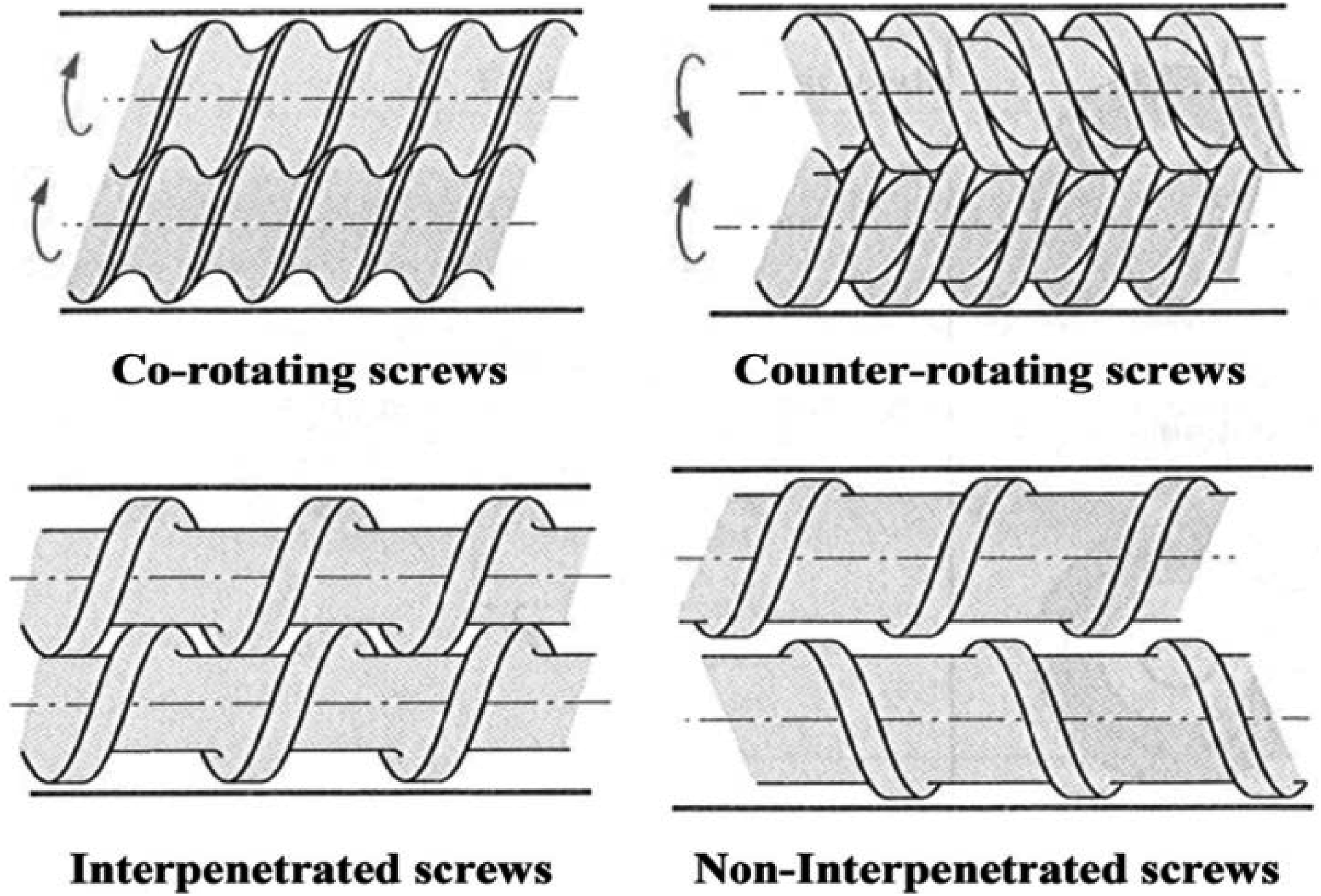

Types of polymer filaments for FDM
Thermal and mechanical properties of common FDM polymer filaments: σ = tensile strength, E = tensile modulus, ε = elongation at break.

Advantages and disadvantages of some commonly used filaments. 50

It was discussed in Fused Deposition Modeling Section above that the mechanical properties of FDM samples are compromised as compared to injection molding. Literature shows that scientists are focusing on improving filaments to get better mechanical performance of FDM parts. Making polymer blends from different materials, adding fibers like carbon fiber, glass fiber and Kevlar® aramid fiber into the polymer matrix and mixing with reinforcement particulates are some of the efforts made by scientists as seen in the literature.
Polymer blend and composite for FDM
Properties of composite filaments for FDM.

Fico et al. 176 used cocoa bean shell waste as a biowaste reinforcement material to PLA. The results presented by the authors showed that the modulus of PLA was increased to 27 MPa from 19 MPa. Due to increase in stiffness, the elongation at break decreased from 4.75% to 3.5%. In a similar research, Sun et al. 177 applied TPS with 70% corn particle and 30% starch on commercial wood filled PLA and observed that thermal degradation temperature decreases with addition of TPS. Filaments with more than one polymer is also reported to perform better than a single polymer filament. Shin et al. 178 made PLA and TPU blend with 50, 70 and 90% TPU. The authors reported that the elongation at break of PLA increased from 4.7% to 15%, 290% and 729% with the addition of 50, 70 and 90% of TPU, respectively. Moreover, rupture energy is also significantly increased from 60.3 J to 6259.7 J with 90% TPU. Assis and Rampazo blended 30% and 40% ABS with PC to make filaments for FDM. 179 They reported that the tensile strength of 60:40 ratio of PC/ABS is 39 MPa whereas the strength of 70:30 PC/ABS blend is 46 MPa.
The literature study suggests that the scientists have mainly focused on three different additives to pure polymer filament: particulate reinforcement, fiber reinforcement and polymer to polymer blend. Particulate reinforcement seems to provide strength and rigidity to the filament. However, it is reported that the processability of the material is adversely affected by the particulates. Fiber reinforced filaments demonstrated higher tensile strength. In the case of both short fiber and long fiber reinforcement, enhanced tensile strength is reported by several researchers. However, the presence of fiber increases stiffness and as a result flexibility is reduced which is undesirable for fabric applications. A solution proposed by the researchers is to blend of different polymers together. Individual polymers have specific mechanical behavior depending upon the long chain nature. For instance, PLA has higher strength but lower elongation whereas TPU has low strength but high elongation. Scientists have reported that the blended filament of these two materials provides a better combination of strength and flexibility. It can be concluded that polymer blends of specific materials can provide suitable filaments for producing interlaced flexible structures.
Application of FDM in flexible fabric structures
Application of flexible fabric structures is not limited to clothing and footwear in this modern era. They are also used in biomedical, aerospace, safety and defense, filtration, civil engineering, automotive, paper making, sports, and infrastructure applications. Due to advancements in additive manufacturing, nanotechnology and new material development, the role of textiles has expanded, demonstrating the industry’s versatility and increasing significance in various sectors. FDM has attracted the attention of the scientific community towards its potential application in manufacturing of textile structures. The conventional way of fabric manufacturing involves several processes beginning with polymer followed by fiber spinning, yarn spinning and fabric making.191,192 Involvement of these tedious steps makes fabric manufacturing process complex, inefficient, and costly. The higher the number of steps, the higher is the solid waste. Latest advancements in FDM technology give opportunity to obtain the desired final shape directly from the polymer. This idea provides the opportunity to produce fabric and textiles directly from polymers eliminating the intermediate processes. This results in a reduction of manufacturing time, cost and solid waste produced during the process. Despite this area of study being nascent, literature shows that scientists are keenly working in this field. In this section, current research in fabric and textile applications of FDM is discussed and the research gaps are identified.
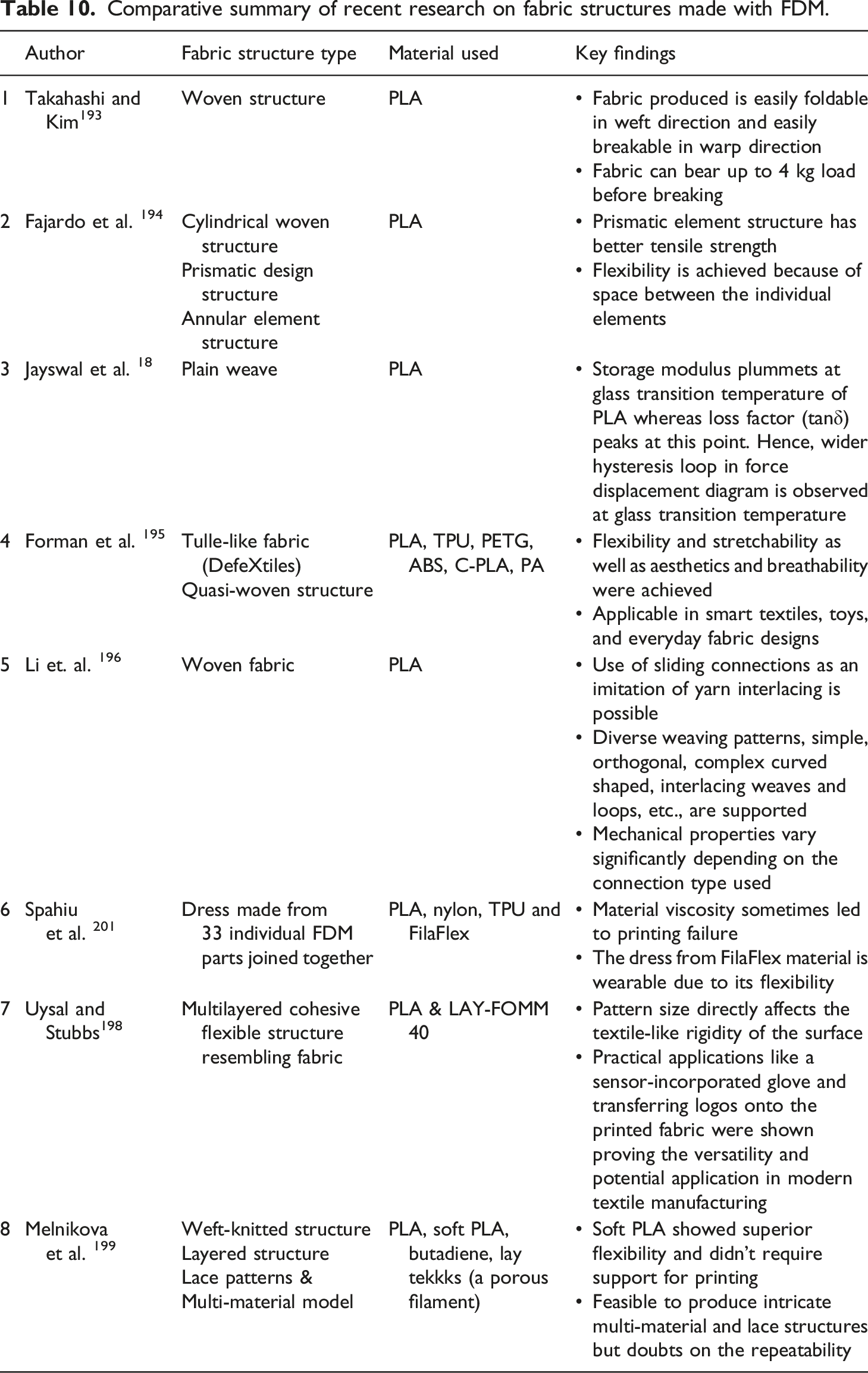
Takahashi and Kim 193 proposed a technique to manufacture woven fabric structures using FDM. They introduced a set of process parameters in FDM which are suitable for producing woven structures, also called programmable textiles by the authors. They used different types of PLA on Creality 3D CR- 10S (power) 3 commercial FDM machine with 0.4 mm nozzle diameter and 300 × 300 × 400 mm printing space. They proposed a design with 3 design elements, namely base, support and weaving fiber where base acts as the support for the entire structure and weaving fiber is extruded with support generated from inner and outer support structures. The thin woven fabric sheet produced in upright position is reported to be foldable in weft direction but easily breakable in warp direction. The fabric produced is reported to bear a load up to 4 kg before breaking.
Fajardo et al. 194 manufactured different designs of structured fabrics using FDM and SLA methods and compared the tensile strength of the designs. A total of 16 specimens (6 specimens of cylindrical woven structure of woven link, 6 specimens of prismatic element structure in woven link and 4 elements for annular element structure in woven link) of fabric were produced. The properties of textiles such as fabric areal density, fineness and fabric flexibility were reported. Their results suggested that tensile strength of the fabric significantly depends on the design of the fabric as the structured fabric formed by prismatic element has better tensile strength compared to the structured fabric from cylindrical and annular elements. Their results also showed that the linked nature of the elements, unlike interlinked structure of traditional textiles, governs the degree of flexibility of the parts produced. This is mainly because of the space between individual elements and this effect is accumulated due to the large number of elements in the structure. The authors also suggest that further study on geometry of the structure is necessary to mitigate stress concentrations and improve textile comfort.
Jayswal et al.
18
produced interlaced woven fabric structures and studied the viscoelastic behavior of the parts. The time dependent mechanical response, determined using viscoelastic model, is represented in a Prony series. Furthermore, a unit cell of fabric structure was manufactured using PLA and was subjected to dynamic mechanical analysis (DMA). The experimental results were used to validate the computational results to further predict the behavior of larger fabric structures. The viscoelastic master curve is presented by the authors from Time Temperature Superposition Principle (TTSP) of DMA as shown in Figure 9 (left), where Viscoelastic behavior of FDM woven fabric - viscoelastic master curve (left): Force-displacement diagram of the fabric (right).
18

Forman et al. 195 developed a cost effective and a quick process to produce tulle-like fabrics to which they named as DefeXtiles. They used under-extrusion phenomenon to develop quasi-woven fabrics with the ability to control printing of micro to large scale structures with easily available 3D printing materials. They claim that complex geometries (e.g., pleated, curved, etc.,) and metamaterials can be printed using this technique as it facilitates textile prints to be printed perpendicularly to the print bed. Small globes elongated in print direction generate a quasi-warp yarn structure while fine filament strands form the quasi-weft yarn. To control the drift of the pillars, the print head’s movement direction is altered as per the requirement. Textile properties like flexibility and stretchability as well as aesthetics and breathability were achieved. This technique potentially has a broad application including smart textiles, toys, and everyday fabric designs which can be achieved using several material choices and printing parameters to change the mechanical and visual properties of the fabrics.
Li et al. 196 were successful in producing 3D printable textile-like materials that featured sliding connections as a replication of interlacing of yarns for woven fabric structures. These sliding connections enable the strands to move relative to each other, which opens possibilities for materials with programmable, non-linear, and direction-dependent properties. Standard planar grids were modified by incorporating sliding connections at intersections. One strand is printed flat, and another is overlaid with a slight elevation of the print head generating an arc shaped channel that allows the movement without direct attachments between the two yarns in the crossing. Diverse weaving patterns, ranging from simple orthogonal weaves to complex curved and interlacing weaves and loops are supported by this technique. The study demonstrated that the mechanical behavior of these materials varies dramatically based on the connection type. Structures with all-sliding connections are highly flexible and can be easily transformed into different shapes like flat to parabolic deployments with little resistance whereas all-fused connections are stiffer and show quasi-isotropic responses.
Spahiu et al. 197 studied the applications of FDM in clothing production. They manufactured a dress made up of 33 individual parts by 3D printing which took them 75 h to print the parts. The parts were joined using a Dikale 07A 3D Pen. The design was made in Tinkercad and was tested for a wide range of materials from rigid to flexible, including PLA, nylon, and TPU. They also carried out a survey about the knowledge and reaction of people to 3D printed fabrics and concluded that there was a significant awareness of 3D printing and its benefits among the people. They were excited to use the 3D printed cloth. They found out that material viscosity sometimes led to printing failure. They made a dress using FilaFlex material that was flexible, appealing due to its “nude” color, comfortable and was enhanced for wearability. Survey results were in support for the adoption of 3D printed fabrics as the participants were optimistic about the future of 3D printing in garment and fashion industries.
Uysal and Stubbs 198 came up with a novel method for printing multi-material textiles incorporating FDM in their research. They developed wearable garments by combining various materials into a cohesive, flexible structure that resembled textile surfaces. The process began with detailed sketches of each print layer followed by converting into 3Dmodels using Blender. It was then preprepared for slicing and printing with Autodesk Netfabb. PLA was used in the first four odd layers for patterns in an 11 layered structure and the remaining ones used LAY-FOMM 40, a micro-porous elastomer with a water soluble PVA filler that was later dyed. The results showed that the pattern size directly affected the textile-like rigidity of the surface and the overall printing time. For instance, smaller and more intricate patterns took longer time and were rigid and had higher tensile strength. They concluded that multi-stage conventional textile production steps can be integrated into a single 3D printing process. They implemented practical applications like a sensor-incorporated glove and transferring logos onto the printed fabric that showcased the versatility and potential of this technology in modern textile manufacturing.
Melnikova et al. 199 explored a range of standard and innovative materials such as PLA, soft PLA, butadiene, etc. ABS was discarded due to its insufficient mechanical properties after the first test. They compared FDM process with Selective Laser Sintering (SLS) of nylon by producing several structures like weft-knitted, layered, lace patterns and multi-material models. The team utilized BlenderTM to modify and deform knitted stitch models developed in Adobe Illustrator, and Netfabb to confirm the designs’ printability. Lay Tekkks, a porous filament that softens after being immersed in warm water was used while generating the lace patterns. It was left in water for 3 hours. There were issues with the fine support structures and material flexibility for some materials, but soft PLA yielded superior results as it did not require any kind of support. They concluded that replication of textile structures in 3D may not always yield ideal results, but it is feasible to produce intricate multi-material and lace structures effectively that have significant applications in textiles.
This part of the review work has extensively focused on making fabric structures using FDM. It should be noted that FDM has its applications in deposition of polymers in fabric-like structures or textiles. Franco-Urquiza et al. 200 assessed the potential of generating PLA composites using jute plant fiber woven fabrics as filler. Characterization of dog bone tensile samples made from PLA-fused filaments deposited on natural woven jute fabrics was carried out; however, the mechanical properties obtained from the composite were not satisfactory. The jute fabrics were modified for better adhesion with PLA, but the interaction was still inadequate. Similarly, Spahiu et al. 201 studied the effect of 3D imprinted patterns on fabric drape. They rigorously evaluated how various geometrical patterns such as squares, triangles, and circles affect garment drape using a skirt. Some designs were printed along the outer parts of fabrics to maintain wearing comfort while some covered the entire fabric. A few patterns were later discarded due to excessive stiffness. They used white polyester and grey polyamide with specific thickness and areal weight. PLA was taken as a filament material for printing which, according to the authors, had an excellent adhesion with textiles. Pei et al. 202 and Grimmelsmann et al. 203 showed that PLA has better adhesion to textiles as compared to other filaments. The drape coefficient, number of nodes, and the pattern’s spatial arrangement played a crucial role in fabric behavior such as fabric’s flow and appearance in the final garment. They concluded that the pattern’s arrangement critically influenced those variables. The final garment appearance of the skirt made from the modified fabrics visually demonstrated these changes. This highlighted how 3D printing can dynamically influence textile design.
Comparative summary of recent research on fabric structures made with FDM.
Conclusions
Fused deposition modeling has several benefits over traditional manufacturing methods. Ability to produce intricate designs, rapid and on-site design change, personalized design and wide range of materials make FDM popular among engineers. However, FDM suffers from a major setback – compromise on mechanical properties and surface quality. Literature shows that the mechanical behavior of FDM parts such as tensile strength and modulus is significantly less than those of injection molded parts of the same material. These findings impose an important research question: why are the mechanical properties hindered? The common answer to this question is that FDM parts have layer by layer geometry which has voids and plenty of interlayer bonding. Voids weaken load bearing ability and interlayer bonds are prone to failure easily. Moreover, circular shaped extrusion of material and layer-by-layer deposition negatively affects the surface quality of the product.
Literature suggests that process parameters directly influence the mechanical performance and surface quality of the product. Many authors have reported that the parameters like extrusion temperature, layer height, raster angle, print orientation and print speed directly influence the properties of the product. The methodology adapted by researchers to find the effects of these variables is selecting multilevel variables for a few important parameters while keeping other parameters constant. Researchers also reported some optimum level of process parameters for different materials. Results from various researchers show that, although the nature of the effect is same, the degree of the effect on performance of a part varies with the material. An example of this is optimum build orientation which is different for ABS, PLA and nylon for maximum tensile strength. Another conclusion drawn from the literature is that the degree of influence of process parameters have interdependence on each other. Hence, there is a certain research gap in this area.
Another area this article covers is the materials for FDM. There are many materials that can be processed with FDM. This article investigates the current efforts made by researchers to make better materials. It is reasonable to conclude that scientists are mainly focusing on making polymer composites and blends to enhance the quality of the final product. In general, polymer composite filaments are made by adding either particulates or short fibers to the polymer base. Polymer-to-polymer blend can be another solution to make filaments for specific applications such as flexible structures. Although several authors attempted to produce interlaced fabric structures with FDM, lack of strength and flexibility remains the main drawback. Moreover, it is observed in the literature that control of process parameters is also a challenge in making fabrics.
Future work
Latest advancements in 3D printed fabrics present an opportunity to researchers in this field but it poses several challenges as well. The very first question is how to produce samples with different designs. Moreover, strength and flexibility are concerns associated with these structures. Another concern is the comfort of these products. Analytical studies of these fabric structures under different loading conditions need to be performed for filtration and other applications. The future roadmap should focus on dealing with these major research gaps. Since the researchers have successfully established the idea that process parameter optimization enhances the performance of the rigid products, this approach should be adapted for fabric structures as well. New research needs to focus on better understanding of how individual process parameters impact the performance of FDM parts and how this impact changes because of the combined effect with other parameters.
Furthermore, development of new polymer composites and multipolymer blends with higher strength, flexibility and wear resistivity should be taken into consideration. The comfort level of FDM fabrics should be another area of future research. Regarding the analysis of mechanical behavior of fabrics, Multiphysics analysis, creep behavior and fatigue behavior of the different fabric structures are needed. There is a plethora of woven, knitted and braided fabric designs. Adapting these designs and analyzing their performance under various loading conditions is essential research work to be done before full acceptance of FDM fabrics in various industry applications.
Footnotes
Declaration of conflicting interests
The author(s) declared no potential conflicts of interest with respect to the research, authorship, and/or publication of this article.
Funding
The author(s) disclosed receipt of the following financial support for the research, authorship, and/or publication of this article: This work has been supported by Auburn University, Department of Mechanical Engineering, which is appreciated.