
Abstract
The electrospinning process parameters for producing polyamide 11 (PA11) nanofibers using formic acid (FA) as the solvent were investigated. Key variables such as solution concentration, tip-to-collector distance, applied voltage, flow rate, and the introduction of a second electric field were optimized to produce uniform, bead-free nanofibers. Preliminary studies indicated that a 10% (w/v) PA11/FA solution concentration, a 25 kV voltage applied to the collector, a 12 cm tip-to-collector distance and a flow rate of 0.03 mL/min yielded the most consistent results in a conventional nozzle electrospinning setup. The effects of distance, voltage, and flow rate on fiber morphology were examined, with increased distance producing thinner fibers due to improved solvent evaporation, while higher voltages resulted in thicker fibers, highlighting the complex interplay between these parameters. Flow rate also played a significant role in fiber formation. The incorporation of charged metallic rings along the jet path, introducing a second electric field, further improved fiber uniformity. The most significant effect on the morphology of electrospun PA11 fibers was observed with rings connected to increasing voltage values, resulting in fibers with an average diameter of 145.7 ± 23.7 nm, minimal bead formation, and uniform circular cross-section. These optimized electrospinning parameters and the application of a second electric field show potential for improving fiber quality in applications such as filtration, textiles, and tissue engineering, contributing to a deeper understanding of PA11 electrospinning.
Introduction
Electrospinning is a cost-effective technology that employs electrostatic attraction, between a charged polymer solution and a collector plate to produce nonwoven mats of polymer fibers with diameters on the order of a few nanometers.
The electrospun nonwoven mats have superior mechanical properties, including a high surface-to-volume ratio, high porosity, small pore size, and ease of functionalization. As a result of these proprieties, they have applications in protective clothing,1–3 filtration,4,5 membranes,6–9 reinforcing fibers in composite materials, 10 optical sensors and electronics,11,12 drug delivery systems,13,14 biomedical applications,15–17 tissue engineering support, 18 and as models for the formation of hollow fibers with internal diameters on the nanometer scale. 19
The diameters of polyamide fibers produced by traditional methods, such as melt spinning and wet and dry spinning, range from 10 to 500 μm. In contrast, fibers produced by electrospinning from polymer solutions typically have diameters in the range from a few tens to a few hundred nanometers. When a greater specific surface area is desired, smaller diameters are preferable. In addition to the fiber diameter at the nanoscale range, the production of smooth, uniform, bead-free nanofibers and the absence of discrete polymer beads in the deposited material are essential for improving the structural quality of electrospun mats, making them suitable for a variety of industrial applications.
Conventional electrospinning of polymer solutions is generally performed using the capillary method, where a charged drop of solution forms at the tip of a capillary or needle and is subjected to an electrostatic field. The field intensity is determined by the applied electric potential between the capillary and the collector (where the electrospun nanofibers are deposited), as well as by the distance between the two. In the electrospinning process, the applied electric field causes charges to accumulate on the surface of the polymer solution droplet at the capillary or needle tip, leading to a conical deformation of the droplet and the formation of the Taylor cone. 20 When the electric field reaches a critical value, a continuous, electrically charged jet of polymer solution is ejected from the apex of the cone. This occurs when the electrostatic repulsion between the surface charges overcomes the surface tension of the polymer solution.9,20
The charged jet of polymer solution is then stretched under the influence of the electrostatic field as it moves toward the collector. Initially, the jet follows an almost rectilinear path, on the order of several millimeters, until it undergoes a bending instability due to its interaction with the electrostatic field, causing it to diverge and follow a complex and random trajectory with several loops.21,22 A series of decreasing-diameter bending instabilities is observed before the jet reaches the collector.21,23 These instabilities are crucial for elongating the jet, leading to the formation of nanofibers. As the jet travels, the solvent evaporates, and the polymer jet undergoes stretching and acceleration, ultimately depositing the resulting fibers onto the collector. A steady-state Taylor cone is essential for ensuring a stable electrospinning process, which controls nanofiber diameter and morphology. 24 Irregular or unstable Taylor cones can result in non-uniform fibers or bead formation. 24
One challenge in electrospinning is the randomness of fiber deposition, which can make it difficult to collect fibers as yarn or to deposit fibers precisely on a substrate. To address this, several researchers have made attempts to control the electrospinning jet by applying an additional magnetic field25–27 or a secondary external electric field between the needle and the collector.28–30 For example, Yang et al. 25 added two magnets to a conventional setup for electrospinning fibers containing magnetic nanoparticles, achieving aligned structures within the magnetic field. With the same purpose, Orr et al. 26 used ceramic magnets together with copper electrodes to collect aligned fibers using a parallel electrode arrangement. Guarino et al. 27 used magnetic field-assisted electrospinning to produce polymer nanofiber yarns that incorporate longitudinally oriented magnetic particles. Deitzel et al. 28 reported the reduction or elimination of bending instability and controlled fiber deposition by incorporating eight copper rings connected to the same positive voltage into a standard electrospinning setup. These rings were placed along the jet path between the positively charged syringe needle and the collection target connected to the negative polarity of the power supply. Stankus et al. 29 used a positively charged cylindrical steel mesh screen near the tip of a positively charged steel capillary to control the area of fiber deposition on a negatively charged collector. Similarly, Gao et al. 30 improved a parallel electrode electrospinning setup by adding two positively charged copper rings between the needle and the parallel electrode collector to produce highly ordered fibers.
The current research focuses on modifying the electric field during the electrospinning of polyamide 11 (PA11) nanofibers by adding several charged metallic rings along the path of the polymer jet. The impact of this modification on fiber morphology, average diameter, and deposition area was investigated, building on our previous research on the electrospinning of polyamide 6 (PA6) and polyamide 6.6 (PA6.6). 31 By strategically placing charged rings between the needle and the collector, the trajectory of the charged polymer jet is altered, affecting fiber morphology, diameter, and deposition area. The electrospinning setup from our previous research, 31 featuring three metallic rings connected to different potential values, allows for greater control of the charged jet during electrospinning.
Regarding the electrospinning of PA11 nanofibers, the number of published studies on PA11 is relatively small compared to research on PA6 and PA6.6. The longer non-polar chain segments of PA11 suggest a higher dielectric strength in electrospun fibers compared to PA6 and PA6.6, which could be advantageous for applications such as filtration, where electrostatic attraction plays a crucial role. However, the solubility of PA11 in polar formic acid (FA) is lower, and electrospinning PA11/FA solutions may be more challenging due to the increase in the length of the polymer chain segments. The hydrogen bonds of the amide are polar, while the methylene groups between the amides are non-polar. In PA11, the segments of diacids and diamines are longer and therefore the concentration of hydrogen bonds is lower than in PA6 and PA6.6. Additionally, PA11 also has lower stiffness, tensile strength, and melting point compared to PA6 and PA6.6, but offers superior chemical resistance and lower moisture absorption. 32 So, PA11 finds applications in several industrial fields, and particularly in the field of industrial textiles, and is widely used in filters, technical textiles, shoe soles, etc.
The morphology of electrospun fibers from polymeric solution depends on several factors, including polymer molecular weight, solvent system, solution concentration, viscosity, conductivity, ambient temperature, relative humidity, and process parameters. 33 In this research, preliminary investigations on solution concentration and process parameters (voltage, tip-to-collector distance, and flow rate) were conducted before adding metallic rings to a conventional electrospinning setup. This allowed the determination of optimal conditions for electrospinning PA11 solutions and assess the effects of modifying the electric field on the electrospun PA11 fiber mats.
Materials and methods
Polyamide-11 solutions preparation
PA11, due to its long hydrocarbon chains, exhibits low solubility in most common solvents, including strong mineral and organic acids. Unlike PA6 and PA6.6 which have good solubility in strong acids, such as formic and dichloroacetic acid, a solvation effect in formic acid (FA) was observed for PA11, but not necessarily leading to its complete dissolution. Behler et al. 34 tested several mixtures of two solvents, one of them hydrophilic and the other hydrophobic, to find a solvent system for the different polyamides. Among all the solvent combinations tested, the 1:1 volumetric mixture of formic acid (FA) and dichloromethane (DCM) was found to completely dissolve the PA11 pellets, allowing for their subsequent electrospinning. 34 However, in several other studies, PA11 solutions for electrospinning were prepared using formic acid alone as the solvent system.35–37
In this research, homogeneous solutions of polyamide 11 (PA11) with concentrations of 6%, 8%, 10%, and 12% (w/v) were prepared using 98% (v/v) formic acid (Merck) as the solvent system for the electrospinning of PA11 nanofibers. The PA11 pellets (Sigma Aldrich) were dissolved in 98 % (v/v) FA (Merck) with magnetic stirring at 300 r/min in a polyethylene glycol (PEG) bath at a temperature of 90°C for 2 hours. For the concentrations used in this work, complete dissolution of the PA11 pellets was observed. No salt was added to the solution since its conductivity was found to be suitable for electrospinning. The solutions were allowed to cool to room temperature. Electrospinning was conducted at room temperature without controlling the relative humidity.
The dynamic viscosity of the solutions was measured at a temperature of 23°C using a RheoStress® RS150 (Haake) rheometer, in shear stress sweep test with a plate of 35 mm and an angle of 2°. The solution conductivity was measured at room temperature with an inoLab® Cond Level2 (WTW), with the reference temperature set to 25°C. Each measurement was repeated three times for accuracy.
Equipment and measurements
The conventional electrospinning setup used in this research to investigate the effects of solution concentration and process parameters on the production of non-woven PA11 nanofiber mats has been previously described in our previous work. 31 The syringe was positioned horizontally and perpendicular to a collector plate covered with aluminum foil. The potential difference between the syringe needle and the collector was applied using a High-voltage (HV) direct current (DC) power supply Glassman model PS/ML40N07.5. The voltage values used ranged from +15 to +25 kV. The solution was fed by a syringe pump (Harvard model PHD 2000 Infusion) that maintains a constant flow rate through a 25-gauge stainless-steel needle with an inner diameter of 0.25 mm and outer diameter of 0.52 mm (Nordson EFD Precision Dispense Tip).
To investigate the effect of adding a second electric field on the production of PA11 nanofibers, three charged stainless-steel rings were incorporated into our conventional electrospinning apparatus, as described in our previous research.
31
These rings with a diameter of 10 cm were positioned between the needle tip and the collector and connected to a second HV power supply Glassman model PS/ML40N07.5. Three different configurations were used for connecting the stainless-steel rings to the second HV power supply (S2). In one configuration (Figure 1(a)), the same voltage value was applied to the rings. In the other two configurations (Figure 1(b) and (c)), a voltage divider was employed to apply different voltage values to each stainless-steel ring. This resulted in either applying increasing voltages (Figure 1(b)) or decreasing voltages (Figure 1(c)) along the needle-to-collector direction. Schematic of the electrospinning setup with the three stainless-steel rings connected to the second HV power supply (S2) with: (a) the three rings connected to the same voltage; (b) the three rings connected to a voltage divider, with increasing voltage and (c) with decreasing voltage. 1 – syringe; 2 – HV power supply 1 (S1); 3 – HV power supply 2 (S2); 4 – collector plate with aluminum foil; 5 – stainless-steel rings; 6 – syringe pump; 7 – voltage divider.
Operating conditions used to investigate the effect of the second electric field in the electrospinning of PA11/AF solutions.
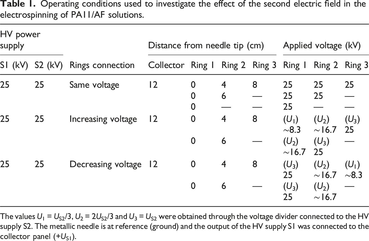
The values U1 = US2/3, U2 = 2US2/3 and U3 = US2 were obtained through the voltage divider connected to the HV supply S2. The metallic needle is at reference (ground) and the output of the HV supply S1 was connected to the collector panel (+US1).
The electrospun mats of PA11 was characterized using scanning electron microscopy (SEM). The morphology of PA11 electrospun nanofibers was examined using a scanning electron microscope Hitachi model S-3400N operating at a voltage of 20 kV. Before SEM analysis, the samples were coated with gold.
The average diameter of the fibers was statistically calculated from 30 manual measurements taken from SEM images with a magnification of 10000x.
A quantitative statistical analysis was conducted using Python software to evaluate the significance of the differences in the average diameters of PA11 nanofibers produced under various electrospinning conditions. The Shapiro-Wilk test was used to assess the normality of the distribution of the fiber diameters measured from each SEM image, while the Levene test was used to assess the homogeneity of variances between two or more groups of measured fiber diameters. To assess the significance of the difference between the mean diameters for two groups, the Student's t-test was used when the data in both groups are normally distributed and the variances between the groups are equal (homogeneity of variances). When the measured fiber diameters in both groups are normally distributed but the variances between the two groups were not equal, the Welch’s t-test was applied. For comparisons involving more than two groups, a one-way ANOVA test was used to assess the significance of differences between mean diameters when both normality and homogeneity of variances were satisfied. If the data in all groups were normally distributed but the variances between the groups were unequal, Welch’s ANOVA was applied. When the fiber diameters were not normally distributed, the non-parametric Kruskal-Wallis test was used to evaluate differences in fiber diameter distributions across groups. Additionally, post hoc tests were conducted when a statistically significant result was found: Tukey’s HSD for one-way ANOVA, Games-Howell for Welch’s ANOVA, and Dunn’s test with Bonferroni correction for the Kruskal-Wallis test. These post hoc tests identified which specific groups differed from one another. A significance level of 0.05 was used for all statistical tests.
Results and discussion
Preliminary studies
Solutions of PA11 in 98% (v/v) FA with concentrations ranging from 6% to 12% (w/v) were initially used to investigate the relationship between concentration and the morphology of electrospun fibers. These solutions were also used to determine the conditions required for achieving a continuous flow of solution at the needle tip during electrospinning. A single HV power supply (S1) was used to maintain a constant voltage of 25 kV between the needle and the collector, with the collector connected to the positive output and the needle connected to the reference (ground) of the HV power supply.
Preliminary studies were conducted with the collector placed at various distances and with different flow rate values. It was found that the most consistent results were achieved when the collector was placed 12 cm away from the needle tip and the syringe pump was set to maintain a feed rate of 0.03 mL/min.
At a concentration of 6% (w/v), only droplets were formed rather than fibers, regardless of the flow rate used. With a tip-to-collector distance of 12 cm, the polymer solution ejected from the needle tip failed to reach the collector, instead falling as droplets along the path. Even when the tip-to-collector distance was reduced to 4 cm, the polymer solution still reached the collector solely in the form of droplets. These results are linked to low solution viscosity, which leads to inadequate polymer chain entanglement, a crucial factor for sustaining a continuous jet during the electrospinning of polymeric solutions. For low viscosity solutions beads and broken fibers will be produced. The viscosity of a polymer solution correlates directly with both the concentration of the solution and the molecular weight of the polymer, and it is also influenced by the solvent system used to dissolve the polymer. The low viscosity observed in the 6% (w/v) solution could be attributed to either the low molecular weight of the PA11 pellets or the low concentration of the solution. Electrospinning requires a minimum solution concentration to ensure stable fiber formation during the process. 33 Typically, concentrations below this critical point result in the formation of beads rather than fibers. 38 At higher concentrations, it was observed that maintaining a continuous flow of the solution became challenging and often led to needle clogging. This issue prevented the successful production of electrospun fibers from the PA11 solution at a concentration of 12% (w/v). Based on these preliminary findings, PA11/FA solutions with concentrations of 8% and 10% (w/v) were used in the subsequent studies.
Our results are consistent with those observed by other researchers. Dhanalakshmi et al. 35 electrospun PA11 solutions in FA with concentrations ranging from 5% to 20% (w/v), voltages between 5 and 20 kV, and collector distances between 5 and 15 cm. They reported that, for PA11/FA solutions at a concentration of 5% (w/v), continuous jet flow was achievable only at a voltage of 20 kV, while lower voltages led to the formation of beads. Continuous polymer solution jets were observed for all applied voltages only when PA11 concentrations in the solution exceeded 10% (w/v). 35 In similar research conducted by Dhanalakshmi and Jog, 36 PA11 nanofiber mats were obtained by electrospinning from solutions of PA11 in FA with concentrations of 10% and 20% (w/w). For the 10% (w/w) solution they obtained uniform nanofibers of circular section with an approximate diameter of 300 nm, but for the 20% (w/w) solution the formation of ribbon-like fibers was observed. 36
Measured viscosity and conductivity of the solutions used in this research, prepared from PA11 pellets in FA (98% (v/v)).

The SEM images with a magnification of 3000x of PA11 nanofibers electrospun from the solutions with concentrations of 8% and 10% (w/v) were shown in Figure 2 and the calculated average fiber diameters are given in Table 3. Effects of concentration on PA11 fibers morphology at voltage of 25 kV, distance of 12 cm and flow rate of 0.03 mL/min. SEM images (magnification of 3000x) of electrospun PA11 mats from PA11/FA (98% (v/v)) solutions with concentrations of: (a) 8 and (b) 10% (w/v). Corresponding histograms of the fiber diameter for: (c) 8 and (d) 10% (w/v) (30 measured diameters for each SEM image at x10000). Average diameter of PA11 nanofibers obtained from electrospinning of PA11/FA solutions with different concentrations.
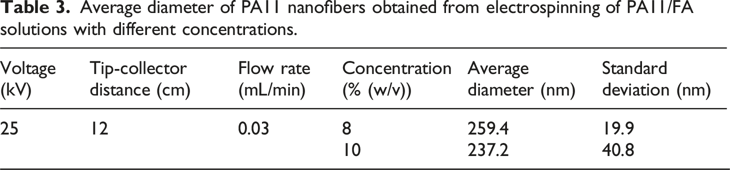
To evaluate the impact of solution concentration on the diameter of PA11 fibers produced through electrospinning, a series of statistical analyses were conducted. The Shapiro-Wilk test for normality distribution and Levene’s test for homogeneity of variances were conducted on fiber diameters data for the two solution concentrations (8% and 10% (w/v)). The Shapiro-Wilk tests indicated that the data for the 8% (w/v) solution concentration (W = 0.978, p = 0.766) and the 10% (w/v) solution concentration (W = 0.977, p = 0.755) fail to reject the null hypothesis of normality in both cases and, consequently, were both consistent with a normal distribution. However, the Levene test indicated that the variances across groups were significantly different (W(1,58) = 15.83, p < 0.001) violating the assumption of equal variances. Consequently, a two group Welch’s t-test was performed to compare the average diameter of PA11 fibers electrospun from solutions with concentrations of 8% and 10% (w/v). The Welch’s t-test indicated a statistically significant difference between the fiber diameters for solution concentrations of 8% and 10% (w/v) (t(40.96) = 2.414, p = 0.020) suggesting that the average fiber diameters for the two concentrations are significantly different.
The average diameter of PA11 nanofibers was observed to decrease as the concentration increased from 8% to 10% (w/v). This unexpected result may be attributed to the lack of stability of the electrospinning process. Specifically, electrospun mats produced from the PA11/FA solution at a concentration of 8% (w/v) displayed a greater prevalence of large fusiform beads (Figure 2(a)). Conversely, increasing the solution concentration to 10% (w/v) enhanced the straightness and uniformity of the fibers (Figure 2(b)). Consequently, solutions of PA11/FA at a concentration of 10% (w/v) were employed, following the optimization of various electrospinning process parameters, to achieve smooth, uniform nanofibers with a cylindrical geometry and minimal bead formation.
Electrospinning process parameters
To investigate the effect of tip-to-collector distance on the morphology of PA11 nanofibers, PA11/FA solutions with a concentration of 10% (w/v) were electrospun. Nanofiber mats were collected at distances of 4, 8, 12, and 16 cm from the needle tip to the collector, with a voltage of +25 kV applied to the collector and a flow rate of 0.03 mL/min. Each electrospun mat was collected over a period of 15 min.
The average fiber diameter and corresponding standard deviation calculated for each electrospun sample are shown in Figure 3(a). As the tip-to-collector distance increased from 4 cm to 16 cm, the average diameter decreased from 383.9 ± 96.2 nm to 215.9 ± 48.7 nm. The Shapiro-Wilk test indicated that the fiber diameters measured from the electrospun sample at a tip-to-collector distance of 4 cm (W = 0.917, p = 0.023) did not follow a normal distribution, while the samples for 8, 12, and 16 cm had p-values greater than 0.05, suggesting that these datasets followed a normal distribution. The results of the Levene test indicated a significant difference in variance across the four groups (W(3,116) = 3.71, p = 0.014). Due to the non-normality in the 4 cm group and the unequal variances, a Kruskal-Wallis test was conducted to compare the fiber diameter distributions across the four distances. The Kruskal-Wallis test suggested a highly significant difference in fiber diameter distributions between the various distances, H(3) = 62.32, p < 0.001. This result supports the hypothesis that the tip-to-collector distance has a statistically significant effect on the fiber diameters produced by electrospinning. Following the Kruskal-Wallis test, Dunn’s test with Bonferroni correction was applied to identify specific group differences in fiber diameters. Dunn’s test revealed significant differences in fiber diameter distributions between the electrospun mats produced at 4 cm and all other distances: 4 cm and 8 cm (p = 0.008), 4 cm and 12 cm (p < 0.001), 4 cm and 16 cm (p < 0.001). Additionally, a statistically significant difference was found between the fiber diameters produced at 8 cm and those at 12 (p = 0.017) and 16 cm (p < 0.001). However, no significant difference was found between the distributions of fiber diameters produced at 12 and 16 cm (p = 1.000). Average diameter of PA11 fibers for different values of: (a) tip-to-collector distance (for a voltage of 25 kV); (b) applied voltage (for 4 and 8 cm). Electrospinning from PA11/FA (98% (v/v)) solutions with a concentration of 10% (w/v) and with a flow rate of 0.03 mL/min.
Typically, increasing the tip-to-collector distance results in a reduction in the average fiber diameter. 23 At a constant voltage, a greater distance leads to a longer flight time for the jet, however, it also reduces the electric field intensity. While the charged jet is under the influence of the electric field for a longer duration, the field strength is lower. As a result, the relationship between fiber diameter and tip-to-collector distance is not always straightforward. In some cases, increasing the distance (and thereby lowering the field strength) results in an increase in average fiber diameter, whereas in other cases, it leads to a decrease in diameter. 39 Additionally, the extended flight time allows more solvent to evaporate before fiber deposition on the collector, improving fiber uniformity and reducing the occurrence of beaded fibers and ribbons.20,40 However, solvent evaporation is also influenced by other factors, such as solvent volatility and ambient conditions (e.g., temperature and relative humidity). These factors together contribute to the complex dynamics of electrospinning and its effects on fiber morphology.
The SEM images of PA11 fiber samples obtained at 4 cm and 16 cm are shown in Figure 4. At a distance of 4 cm (Figure 4(a)), the formation of what appear to be ribbons or flat fibers was observed, as indicated by the non-circular cross-sections. The occurrence of flat fibers can be attributed to the very short needle-to-collector distance, which limits the time available for solvent evaporation before fiber deposition. This leads to the deposition of wet fibers that, upon solvent evaporation, result in flattened cross-sections.
41
In contrast, at 16 cm (Figure 4(b)), fibers with circular cross-sections, lower average diameters, and reduced standard deviations were observed. This suggests that the increased distance allows for better solvent evaporation, resulting in improved fiber morphology compared to the shorter distance. Effects of tip-to-collector distance on PA11 fibers morphology at voltage of 25 kV, solution concentration of 10% (w/v) and flow rate of 0.03 mL/min. SEM images (magnification of 3000x) of electrospun PA11 mats for a tip-to-collector distances of: (a) 4 and (b) 16 cm. Corresponding histograms of the fiber diameter for: (c) 4 and (d) 16 cm (30 measured diameters for each SEM image at x10000).
As no significant difference was found between the fiber diameter distributions produced at 12 and 16 cm (p = 1.000), and based on macroscopic observations of the electrospinning process of PA11 solutions, the optimal tip-to-collector distance was determined to be 12 cm.
To investigate the effect of applied voltage on electrospun PA11 fibers, the syringe needle was connected to the ground of the HV power supply, while the collector panel was connected to +15, +20, and +25 kV. Non-woven mat samples for this set of experiments were produced from a 10% (w/v) PA11 solution in FA (98% (v/v)) at a flow rate of 0.03 mL/min. For any specific voltage, there is a critical tip-to-collector distance beyond which the electrostatic force between the electric charges within the solution decreases significantly. This reduction prevents the formation of the Taylor cone due to the weakened electric stretching forces on the solution drop at the needle tip. 42 Consequently, the electrospinning process at lower applied voltages requires shorter tip-to-collector distances. To ensure fiber deposition on the collector for all voltage values under investigation, tip-to-collector distances of 4 and 8 cm were used.
The average diameters of the electrospun PA11 fibers for the various values of tip-to-collector distance and voltage are presented in Figure 3(b). To investigate the significance of the differences in fiber diameter distributions as a function of applied voltage at a tip-to-collector distance of 4 cm, the Kruskal-Wallis test was applied. This non-parametric test was selected due to the suggested non-normal distribution of the data for 25 kV (W = 0.917, p = 0.023 from the Shapiro-Wilk test) and the presence of equal variances across the groups (W(2,87) = 2.30, p = 0.106 from Levene’s test). The Kruskal-Wallis test indicated a highly significant difference in fiber diameter distributions across the three voltage levels (15 kV, 20 kV, and 25 kV) at a distance of 4 cm, H(2) = 47.83, p < 0.001. Post hoc analysis using Dunn’s test with Bonferroni correction revealed no statistically significant difference in fiber diameter distributions between the 15 kV and 25 kV groups (p = 0.578). However, statistically significant differences were observed between the fiber diameter distributions at 15 kV and 20 kV (p < 0.001), as well as between the 20 kV and 25 kV groups (p < 0.001).
At the tip-to-collector distance of 8 cm, the Shapiro-Wilk test indicated that the fiber diameters obtained for 15 kV (W = 0.97, p = 0.540), 20 kV (W = 0.98, p = 0.866), and 25 kV (W = 0.98, p = 0.701) followed a normal distribution. Additionally, Levene’s test indicated no significant difference in variance between the three groups (W(2,87) = 1.68, p = 0.195). A one-way ANOVA revealed no statistically significant difference in average fiber diameters between the three voltage levels at a tip-to-collector distance of 8 cm (F(2,87) = 2.59, p = 0.081).
The average diameter of the electrospun PA11 fibers was smaller when using a voltage of 20 kV and a tip-to-collector distance of 4 cm (Figure 3(b)). Unlike the tip-to-collector distance, the effect of voltage on fiber diameter is not easily predictable and depends on various parameters. These include the evaporation rate of the solvent or solvents, the tip-to-collector distance, and the flow rate.
An increase in voltage, while maintaining a constant tip-to-collector distance, leads to a higher electric field. Consequently, the repulsive forces between the electric charges at the surface of the solution jet become stronger, leading to a reduction in fiber diameter due to increased stretching of the jet. Conversely, the acceleration of the jet also increases, resulting in a shorter duration for the polymer solution to be drawn, which can lead to larger diameter fibers. 43 Moreover, at higher voltages, there is an increased ejection of solution, promoting the formation of larger diameter fibers and greater dispersion in fiber diameters. 28 These interplaying factors highlight the complex relationship between applied voltage and fiber morphology in the electrospinning process.
SEM images of PA11 fibers at a tip-to-collector distance of 8 cm and applied voltages of +15 kV and +20 kV are shown in Figure 5. Although no statistically significant difference was observed in the average fiber diameters across the three voltages at this distance, smooth fibers were produced at all applied voltages. Effects of applied voltage on PA11 fibers morphology for a solution concentration of 10% (w/v), tip-to-collector distances of 8 cm and a flow rate of 0.03 mL/min. SEM images (magnification of 3000x) of electrospun PA11 mats for a voltage of: (a) 15 and (b) 20 kV. Corresponding histograms of the fiber diameter for: (c) 15 and (d) 20 kV (30 measured diameters for each SEM image at x10000).
At a tip-to-collector distance of 4 cm (Figure 3(b)), it was observed that the average fiber diameters decreased as the voltage increased from 15 kV to 20 kV, but then increased when the voltage was raised to 25 kV. This behavior highlights the complex interplay between applied voltage, tip-to-collector distance, and fiber morphology. 39
Average diameter of PA11 nanofibers obtained from electrospinning of PA11/FA solutions with different flow rates.

At the tip-to-collector distance of 8 cm, the Shapiro-Wilk test indicated that the fiber diameters obtained for both flow rates exhibited normal distribution (flow rate of 0.03 mL/min: W = 0.98, p = 0.701; flow rate of 0.06 mL/min: W = 0.99, p = 0.995) and homogeneity of variances (Levene’s test: W(1, 58) = 0.70, p = 0.406). Therefore, a Student’s t-test was conducted, revealing a highly significant difference between the average fiber diameters produced at flow rates of 0.03 and 0.06 mL/min (t(58) = 6.67, p < 0.001).
At the tip-to-collector distance of 12 cm, the Shapiro-Wilk test indicated that the fiber diameters for both flow rates also followed a normal distribution (flow rate of 0.03 mL/min: W = 0.98, p = 0.755; flow rate of 0.06 mL/min: W = 0.98, p = 0.827). However, the Levene test revealed a significant difference in variance across the two groups (W(1, 58) = 3.71, p = 0.002). Due to these results, Welch’s t-test was applied, yielding t(45) = 5.78, p < 0.001, which demonstrated a statistically significant difference in average fiber diameters between the two flow rates.
Overall, the results confirm that flow rate significantly influences average fiber diameters, with significant differences observed for both tip-to-collector distances (8 cm and 12 cm).
For both tip-to-collector distances considered (8 and 12 cm), the average fiber diameter significantly decreased as the flow rate increased from 0.03 to 0.06 mL/min. Typically, a higher flow rate is associated with an increase in fiber diameter.44,45 However, in cases where the polymer solution concentration is low, an increase in flow rate can unexpectedly lead to a decrease in fiber diameter. 46 This complex relationship highlights the importance of carefully controlling process parameters to achieve the desired fiber morphology in electrospinning.
In the SEM images shown in Figure 6, it is evident that increasing the flow rate from 0.03 to 0.06 mL/min resulted in more uniform PA11 fibers with reduced diameters. Specifically, at a flow rate of 0.03 mL/min, the formation of fibers with fusiform beads was observed. Effects of flow rate on PA11 fibers morphology for a solution concentration of 10% (w/v), voltage of 25 kV and a distance of 12 cm. SEM images (magnification of 3000x) of electrospun PA11 mats for a flow rate of: (a) 0.03 and (b) 0.06 mL/min. Corresponding histograms of the fiber diameter for: (c) 0.03 and (d) 0.06 mL/min (30 measured diameters for each SEM image at x10000).
As the flow rate increases, a larger volume of solution accumulates at the needle tip and, consequently, a higher voltage becomes necessary to stabilize the Taylor cone. When the solution flow rate reaches an optimal level, the rate at which the solution is delivered to the needle tip matches the rate at which it is withdrawn by the jet. This balance allows for stable maintenance of the Taylor cone, resulting in steady-state electrospinning. 47 In steady-state electrospinning, any changes to the applied voltage or tip-to-collector distance require a corresponding adjustment in the flow rate to maintain equilibrium. 48 Achieving steady-state electrospinning for a given polymer solution depends on the careful control of process parameters and is critical for consistent and controlled fiber production in continuous electrospinning.47,48
Electrospinning and electric field
In order to investigate the effect of adding a second electric field on the morphology of electrospun PA11 fibers, our research encompassed the exploration of three different system configurations to modify the electric field during the electrospinning of PA11/FA solutions. In one of the configurations the metallic rings were directly connected to the same voltage (Figure 1(a)), while in the others two, the rings were connected to the second HV supply (S2) through a voltage divider, enabling the application of increasing (Figure 1(b)) or decreasing (Figure 1(c)) voltage values to the rings.
A voltage of +25 kV was selected for both HV power supplies and a consistent 12 cm distance between the needle tip and the collector and a 0.03 mL/min flow rate were maintained across all experiments. The PA11 nanofibers average diameter electrospun under these operating conditions is presented in Figure 7, alongside the respective electrospinning setups detailed in Table 1. Average diameter and standard deviation of PA11 nanofibers produced from electrospinning of PA11/FA solutions with a concentration of 10% (w/v) with a flow rate of 0.03 mL/min and the operation conditions of Table 1.
Statistical analysis was conducted to compare the effects of a second electric field on the diameter of PA11 fibers produced by electrospinning. Comparisons were made between the diameters of fibers produced under different configurations of metallic rings. The six groups analyzed correspond to the following configurations of rings connected to the second high-voltage power supply: Group 1 consisted of one ring connected to 25 kV; Group 2 with two rings connected to 25 kV (same voltage); Group 3 with three rings connected to 25 kV (same voltage); Group 4 with two rings connected to increasing voltages; Group 5 with two rings connected to decreasing voltages; and Group 6 with three rings connected to decreasing voltages. The assumption of normality for each group was assessed using the Shapiro-Wilk test, with results indicating that all groups followed a normal distribution (Group 1: W = 0.969, p = 0.513; Group 2: W = 0.975, p = 0.680; Group 3: W = 0.972, p = 0.593; Group 4: W = 0.983, p = 0.895; Group 5: W = 0.984, p = 0.909; Group 6: W = 0.978, p = 0.758). The Levene’s test indicated a violation of the homogeneity of variances assumption (W(5, 174) = 4.325, p = 0.001). Given the non-homogeneity of variances, Welch’s ANOVA was applied to compare the means of fiber diameters between the six groups. Welch’s ANOVA revealed a highly significant difference in the mean fiber diameters across the six rings configurations (F(5,79) = 50.43, p < 0.001). Following this, the Games-Howell post-hoc test was employed to identify specific pairwise differences between the groups while accounting for unequal variances.
The results of the Games-Howell test demonstrated significant differences in the average fiber diameters between most group pairs. For example, the largest difference was observed between Group 1 (1 ring at 25 kV) and Group 4 (2 rings with increasing voltages), with a mean difference of 201.2 nm (T = 12.48, p < 0.001). Another substantial difference occurred between Group 4 (2 rings with increasing voltages) and Group 6 (3 rings with decreasing voltages), with a mean difference of 91.2 nm (T = −10.16, p < 0.001). These results suggest that the number of rings and the voltage configuration significantly influence the diameter of the fibers produced.
Interestingly, some group comparisons, such as between Group 3 (3 rings at 25 kV) and Group 6 (3 rings with decreasing voltages), did not show significant differences (T = 1.50, p = 0.664), indicating that the fiber diameters produced by these two configurations were statistically similar. Likewise, the difference between Group 1 (1 ring at 25 kV) and Group 2 (2 rings at 25 kV) was not statistically significant (T = 2.53, p = 0.131) as the difference between Group 2 (2 ring at 25 kV) and Group 3 (3 rings at 25 kV) (T = 2.69, p = 0.094), suggesting that using two rings at the same voltage does not substantially alter the fiber diameter.
The results indicated that both the number of rings and the voltage configuration play a critical role in determining fiber diameter. Significant differences were observed between the average fiber diameters produced for different electric field configurations, with the most pronounced effects occurring when the voltage configuration varied between rings.
When employing the system configuration with an equal voltage applied to the rings (Figure 1(a)), a reduction in the average diameter of the fibers deposited on the collector was observed as the number of rings along the path of the jet increased from one to three. This occurrence resulted from the increased electric stretching of the polymer solution due to alterations in the electric field. This effect is clearly visible in the SEM images of the PA11 depositions shown in Figure 8, with a magnification of 3000x, obtained with 1, 2, or 3 metallic rings connected to +25 kV. Effects of the second electric field on PA11 fibers morphology for a solution concentration of 10% (w/v), distance of 12 cm, flow rate of 0.03 mL/min and a voltage of +25 kV applied to the collector. SEM images (magnification of 3000x) of electrospun PA11 mats produced with: (a) 1 ring, (b) 2 rings and (c) 3 rings connected to the same voltage of +25 kV. Corresponding histograms of the fiber diameter for: (d) 1 ring, (e) 2 rings and (f) 3 rings connected to the same voltage (30 measured diameters for each SEM image at x10000).
The results obtained with decreased voltage applied to the rings suggest that increasing the number of rings led to an increase in the average diameter of the electrospun PA11 nanofibers. Specifically, the average diameter of the deposited fibers increased from 206.9 ± 59.0 to 244.1 ± 32.0 nm as the number of rings increased from two to three. However, was observed a significant reduction in the number and size of fusiform beads in the PA11 mats produced with 3 rings (Figure 9(c)). Effects of the second electric field on PA11 fibers morphology for a solution concentration of 10% (w/v), distance of 12 cm, flow rate of 0.03 mL/min and a voltage of +25 kV applied to the collector. SEM images (magnification of 3000x) of electrospun mats of PA11 produced with: (a) 2 rings with increasing voltage and (b) 2 rings and (c) 3 rings with decreasing voltage (values given in Table 1). Corresponding histograms of the fiber diameter for: (d) 2 rings with increasing voltage and (e) 2 rings and (f) 3 rings with decreasing voltage (30 measured diameters for each SEM image at x10000).
The configuration of three metal rings with increasing voltage did not allow to produce PA11 fibers. Despite ejecting the polymer jet from the needle, the polymer solution consistently fell between the needle and the collector. However, electrospun mats of PA11 fibers were successfully obtained with 2 rings with increasing voltage values. The average diameter of the PA11 nanofibers obtained under these conditions (152.9 ± 37.7 nm) was smaller than with the same number of rings connected to decreasing voltage values (206.9 ± 59.0 nm). This observation led to the conclusion that the electric stretching of the PA11 solution is more pronounced when subjected to an electric field with rings connected in the configuration with increasing voltage. It is anticipated that, alongside electric field strength, field geometry plays a significant role in influencing the electrostatic forces responsible for stretching the charged solution jet and, consequently, the electrospinning process.
The quality of electrospun mats is heavily influenced by factors such as dripping, bead formation, and the presence of beaded fibers. Upon analyzing the SEM images of the PA11 depositions obtained for various ring configurations (Figure 9), distinct observations emerge. In the system configuration with 2 rings with decreasing voltage, a larger number of fusiform beads and greater dispersion in fiber diameters is evident (Figure 9(b) and (e)). Conversely, in Figure 9(c), corresponding to the deposition of electrospun fibers with 3 rings with decreasing voltage, fibers appear more uniform with fewer fusiform beads and significantly reduced diameter dispersion. The deposition obtained with 2 rings connected with increasing voltage, depicted in Figure 9(a), also exhibits some fibers with fusiform beads. Across multiple studies, a tendency towards fusiform bead formation in PA11 electrospinning solutions has been noted. Comparatively, the results obtained with the rings connected to the same voltage value (Figure 8) highlight that the electrospinning system with 2 metallic rings connected with increasing voltage yields superior outcomes.
Operating conditions after optimization and average diameter of PA11 nanofibers produced from the electrospinning of 10% (w/v) solutions of PA11 in FA (98% (v/v)) and a flow rate of 0.01 mL/min.
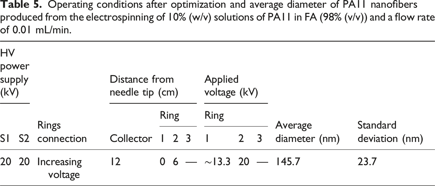
The SEM image in Figure 10(a), with a magnification of 5000x, display the electrospun mats of PA11 produced according to the configurations and operational conditions outlined in Table 5. Analysis of this image revealed the formation of uniform cylindrical nanofibers from the PA11/FA solutions, with an average diameter of 145.7 ± 23.7 nm. Most of the fibers appeared smooth, uniform and devoid of beads. These findings confirm that the selected process parameters can produce nanofiber mats with minimal bead formation and reduced average diameters and standard deviation. (a) SEM image (magnification of x5000) of the PA11 non-woven mats collected using 2 rings connected to increasing voltages (S1 = S2 = +20 kV) from a solution of PA11/FA with a concentration of 10% (w/v), collector at a distance of 12 cm, with a flow rate of 0.01 mL/min and a voltage of +20 kV applied to the collector (Table 5) and (b) corresponding histogram of the fiber diameters (30 measured diameters for the SEM image at x10000).
Compared to the PA11 nanofibers produced using the conventional electrospinning system, a reduction in the average fiber diameter was observed when a second electric field was introduced in the configuration with two metallic rings connected to increasing voltage values. Along with the diameter reduction, the fibers were more uniform, with a smooth surface and a circular cross-section. This improvement in fiber morphology is evident when comparing the SEM image of electrospun PA11 nanofibers produced using the conventional setup (e.g., Figure 3) with the SEM images shown in Figure 10. These enhanced fiber characteristics—diameter, surface texture, and cross-section—are critical as they greatly affect the mechanical properties and performance of the fibers in various applications, including filtration, textiles, tissue engineering, and composites.
In comparison to existing literature, the average diameters of the fibers obtained in this study align with those reported in prior research on electrospinning of PA11 fibers.35,36,49 This consistency further validates the effectiveness of the methodologies employed in this work.
Conclusions
The present study investigated the influence of several electrospinning process parameters, including solution concentration, tip-to-collector distance, applied voltage, flow rate, and the introduction of a second electric field, on the morphology of electrospun PA11 fibers. The results demonstrate the complex interplay between these parameters and their significant effects on fiber diameter, uniformity, and bead formation.
Preliminary studies showed that a 6% (w/v) PA11/FA solution was unsuitable for fiber production, resulting in droplet formation due to low viscosity. Electrospinning at higher concentrations (8% and 10% (w/v)) led to fiber formation, with 10% (w/v) yielding smoother, more uniform fibers. This confirms that solution concentration plays a critical role in fiber formation during electrospinning.
The optimal distance for electrospinning PA11/FA solutions was determined to be 12 cm, where fiber uniformity improved, and bead formation was minimized. The effect of voltage on fiber morphology was complex and dependent on the tip-to-collector distance. While increased voltage generally led to thinner fibers due to greater jet stretching, excessively high voltages resulted in larger fiber diameters due to rapid ejection and insufficient stretching time. The tip-to-collector distance, applied voltage, and flow rate are interrelated. The balance between solution delivery and jet withdrawal rates, highlighting the importance of maintaining steady-state electrospinning.
The addition of a second electric field significantly improved fiber uniformity and reduced diameters, especially when two metallic rings with increasing voltage were used. This setup produced the smallest average fiber diameters (145.7 ± 23.7 nm) with minimal bead formation. The presence of the second field enhanced electric stretching, yielding fibers with smooth surfaces and circular cross-section. This result can be attributed to the regulation of the electrostatic field, which allowed for better control over the inherent instability of the charged polymer jet during its trajectory towards the collector panel.
Overall, the optimized conditions for electrospinning PA11/FA solutions—10% (w/v) concentration, 12 cm tip-to-collector distance, +20 kV voltage, 0.01 mL/min flow rate, and the use of two rings with increasing voltage in a conventional nozzle electrospinning system—resulted in uniform nanofibers with reduced average diameters and minimal bead formation.
These findings contribute to the understanding of PA11 electrospinning and underscore the importance of fine-tuning electrospinning parameters to achieve desirable fiber morphologies for various applications. The methodologies and results align well with previous studies, further validating the approach taken in this work.
Footnotes
Declaration of conflicting interests
The author(s) declared no potential conflicts of interest with respect to the research, authorship, and/or publication of this article.
Funding
The author(s) disclosed receipt of the following financial support for the research, authorship, and/or publication of this article: The authors are very grateful for the support granted by the Research Unit of Fiber Materials and Environmental Technologies (FibEnTech-UBI), through the Project reference UIDB/00195/2020, funded by the Fundação para a Ciência e a Tecnologia, IP/MCTES through national funds (PIDDAC), and DOI: 10.54499/UIDB/00195/2020.