
Abstract
Warp-knitted spacer fabrics (WKSF), with their unique structure and excellent energy absorption properties, are widely utilized in the automotive industry, medical field, and aerospace sectors. However, during practical applications, WKSF undergo repeated compression, which can lead to compressive fatigue of the spacer yarns and consequently cause the WKSF to undergo irreversible deformation, which subsequently affects its performance and appearance. Therefore, to enhance the compressive properties of WKSF and investigate the mechanisms of plastic failure, this study used a warp knitting double needle bar raschel machine to fabricate a WKSF with a thickness of 20 mm. Through fabric structure analysis, we developed a unit cell model consisting of 32 fibers and a more comprehensive analysis model with 320 fibers to quantitatively assess the geometric changes of the WKSF during the compression process. Furthermore, we experimentally studied the performance changes of the WKSF under different compression speeds, various compression strains, and 1000 cycles of loading. By integrating experimental test with the finite element method, we have conducted an in-depth study of the compression process of WKSF, simulating the displacement U, Von Mises stress distribution, and plastic compression failure behavior during compression. By comparing data on Von Mises stress, equivalent plastic strain (PEEQ), and energy density distribution (SENER), we can clearly observe the performance of spacer yarns under compression conditions, providing significant insights into the underlying plastic failure mechanisms of WKSF’s. This study not only enriches the theoretical framework for WKSF compression but also lays a solid foundation for improving its performance and extending its applications.
Keywords
Introduction
The rapid development of the textile industry has led to the widespread application of high-performance textiles in various fields, especially in high-end markets such as daily life, industrial production, aerospace, and more. In high-performance fabrics, three-dimensional fabrics are the most typical, among which, warp-knitted spacer fabrics (WKSF), with unique three-dimensional structure, 1 have demonstrated significant potential in applications such as seat padding, sound insulation materials, and protective equipment. WKSF are produced by double-needle-bar warp knitting machines. 2 They are composed of two sets of surface yarns and spacer yarns, forming a three-layer structure of top surface layer, a spacer layer, and a bottom surface layer. 3 Currently, polyester monofilament with a larger elastic modulus, which is melt-spun from chemical fibers, is commonly used as the spacer yarn. The spacer monofilaments (SMFs) pass through the two surface layers in a specific pattern by guide bars, creating a spacer layer with a certain thickness and spatial structure. WKSF generally uses thicker SMFs as spacer layers to give fabrics excellent compressive properties. As an important part of WKSF, the compressive properties of SMFs directly affect the overall performance and practical application. 4
Due to WKSF’s superior compressive performance, researchers have conducted in-depth studies, which include structural analysis, performance evaluation, mechanism exploration, and finite element simulation modeling. Chen et al. 5 conducted a thorough analysis of the compression theory of SMFs and developed a theoretical model. However, during the model simplification process, they overlooked the influence of the back transverse movement of the guide bar needle and the spacer yarn’s structural pattern on the SMF’s morphology. Furthermore, their research focused primarily on the SMFs, neglecting its applicability to spacer fabrics. Qu et al 6 found that the thicker the diameter of SMFs, the stronger the compressive performance of WKSF. Zhang et al. 7 and Gu et al. 8 found that the use of composite SMFs can significantly improve the compressive properties of WKSF. Ertekin et al. 9 discussed the influence of different heat setting process conditions on the properties of WKSF and revealed the important role of fabric finishing process in enhancing the compressive properties of fabrics. Du et al. 10 and Datta et al. 11 studied the compressive performance of the indenter by simulating different human contact positions of different spherical and curved indenter. It is found that there are many factors affecting the compressive properties of spacer fabrics, including the thickness of spacer yarn, fabric finishing process and test methods. However, these studies only verify and comprehensively evaluate the excellent properties of WKSFs and the factors affecting the excellent properties of WKSFs through experiments, but lack the research on the compression theory of WKSFs. Sun et al. 12 used the finite element method to simulate the compression deformation mechanism of WKSF. However, the simplified model did not truly reflect the unique interloping structure of SMF. They only used simple parallel arranged yarns to simulate the spacer fabric, but the simplified model proposed in this research could not accurately simulate the WKSF. Hou et al. 13 mapped the three-dimensional model of spacer fabric by CT scanning technology, established the unit cell model of SMFs, and studied the compression deformation mechanism of WKSF. However, the interaction between the unit cell was not considered in the research process, and the plastic failure mechanism of spacer fabric was not elaborated in the research process. Zhang et al.14,15 used the finite element method to only study the curvature change and shape change of SMF at different compression stages but lacked research on other properties. Guo et al. 16 determined the potential physical mechanisms of compression deformation in typical structured WKSF through experimental and theoretical analysis. Yu et al.17,18 and Liu et al., 19 among others, respectively used macroscopic and single-cell models to study the stress distribution during the compression process of fabrics through finite element simulation. Although extensive research has been conducted so far, there is still a lack of clear and detailed theoretical analysis on the bending mechanism of SMFs in the finite element simulation compression process, the detailed performance of plastic deformation in specific regions, and the dynamic process of plastic bending region transition in the compression process. More importantly, the unit cell model used in previous studies did not explore the potential influence of unit cell interaction on the compressive behavior of SMFs. In view of this, focusing on the research of the commonly used polyester monofilament; by constructing a more detailed model and performing simulation analysis, we will greatly enhance our understanding of the compression mechanism of WKSFs, thus promoting the progress and improvement of the compression theory of WKSFs.
Finite Element Analysis (FEA), as a technology that uses finite elements to simulate the behavior of complex objects or systems, has been widely used in various fields due to its strong adaptability and flexibility. This technique can solve problems involving complex shapes and boundary conditions while maintaining a high level of calculation accuracy, making it an essential tool in the simulation and research of the compressive process of WKSF. Consequently, this study combines experimental test with FEA to further study the compressive bending plastic damage mechanism of WKSFs. To achieve this, we designed and produced a mesh-structured WKSF using a double-needle-bar warp knitting machine. We systematically analyzed the plate compression performance and compressive bending behavior under different velocities, various strain conditions, and 1000-cycle loading (which means 1000 compression test cycles). Through a detailed spatial position distribution analysis, we constructed a model for the SMFs within the WKSF. This study aims to delve deeply into the compression behavior of WKSFs, utilizing a combined approach of experimental testing and finite element simulation. Special attention is paid to the propagation process and regional distribution of plastic damage in the WKSFs during compression and bending, considering the interaction between SMFs within unit cells. The study aims to further enrich and improve the theoretical framework of WKSFs.
Experimental part
Materials
The typical 3D WKSF featured in Figure 1 were knitted using a warp knitting double needle bar raschel machine RD6N gauge E18 machine with six guide bars. Polyester multifilament, specifically of 150 D/64F, was utilized for the top and bottom surface layers, fed through guide bars GB1, GB2, GB5, and GB6, and top view and bottom view of fabric with same pictures was shown in Figure 1(c). Additionally, polyester monofilaments with a diameter of 0.18 mm served as SMFs, connecting the two outer layers via guide bars GB3 and GB4 in an X-shaped configuration. The WKSF measures 20 mm in thickness and presents a hexagonal mesh structure on its top and bottom surfaces, as depicted in Figure 1(b)–(c), respectively. The weight of the fabric is 1066.30 g/m2, with the number of wales per centimeter of 4.98 loops/cm and courses per centimeter of 9.20 loops/cm. Table 1 shows the detailed preparation parameters for the WKSF. Physical structure morphology of the WKSF. (a) the real image of WKSF; (b) thickness of WKSF; (c) top and bottom view of WKSF. The detailed preparation parameters of warp-knitted spacer fabrics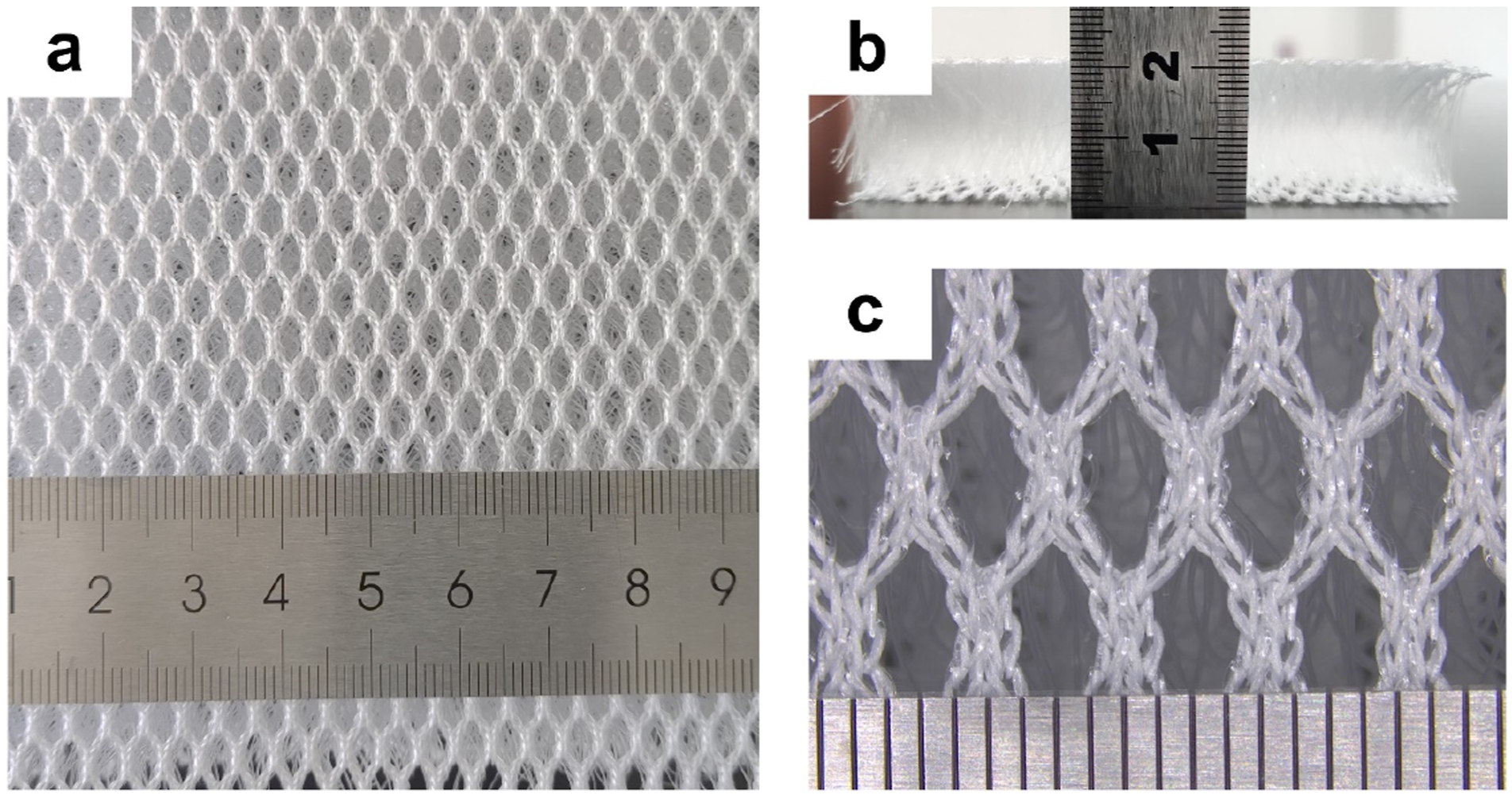

To gain a clearer understanding of the spatial structure and morphology of WKSF, a warp knitting CAD iTDS2.0 system was used to simulate the structure of the WKSF. In the CAD iTDS2.0 system independently developed by our team; the operation process first involves precisely setting the distribution of the layers in the Guide bar module. Following that, it proceeds to the Process Design module where the Chain notation and Threading parameters of the Guide bar are carefully entered. Specifically, in the Yarn module, the yarn type is explicitly specified as filament yarn, and its proportion is set to 1. After completing these steps, by clicking on the Fabric Simulation module, a diagram similar to Figure 2 is generated. As shown in Figure 2(a) and (b), the three-dimensional spatial structure and morphology of the WKSF can be observed from both the top and bottom surfaces. Figure 2(c) and (d) respectively illustrate external and internal side of the top and bottom surfaces of fabric structures knitted by GB1, GB2, GB5, and GB6. In the diagram, it is clearly observable that the loop structure of the surfaces of fabric exhibits different effects on the external and internal sides. Figure 2(e) represents the three-dimensional simulation of the SMFs. By combining Figure 2(f) and (g), the SMFs exhibit a spatially curved state and have an X-shape in weft direction. Figure 2(h) and (i) respectively display the cell unit structure of the SMFs cyclic process. For presenting the interlap, Figure 2(j) shows the guide bas knitting lapping diagrams of chain notations in Table 1. The micro-structure geometrical model of 3D WKSF appearance: (a) and (b) front and back view of complete structure; (c) and (d) external and internal side of outer layer; (e) spacer layer appearance; (f) and (g) front and top view of unit cell of spacer layer; (h)1-0-4-5 cycle process appearance of lapping diagram; (i) 4-5-1-0 cycle process appearance of lapping diagram; (j) knitting lapping diagrams of guide bars.
Quasi-static plate compression test
The quasi-static plate compression test for WKSF was conducted according to the standard GB/T24442.1-2009. The WKSF was tested through MTS Exceed E43 (MTS Systems (China) Co., Ltd., Guangzhou, Guangdong, China), which was shown in Figure 3, and the data were processed to obtain compressive stress-strain curves for the samples. The formulas for compression work and resilience work are respectively as shown in equation (1) and equation (2): Compression test equipment of MTS Exceed E43.


Modeling
Geometrical analysis
The WKSF consists of two surface layer and SMFs connecting the two layers, and the compression force is mainly caused by the SMFs bearing pressure. The structure of the surface layer is complicated, and it is fixed inside the face layer of warp knitting structure, and the position remain almost unchanged during the compression process. The arrangement and shape of SMFs are not completely consistent due to the fabric structure. To further study the compression process of SMFs, the following assumptions are made for the WKSF model: (1) In order to further study the deformation during the compression process, the influence of the surface WKSF on the compression deformation of the SMFs are ignored. (2) The SMFs bundles are constrained in the warp knit fabric, and the ends of the SMFs do not undergo relative displacement perpendicular to the compression direction. (3) The thickness of the SMFs is uniform, the cross-section is circular, and it is an isotropic elastoplastic material. (4) SMFs will contact each other during the compression process, resulting in friction and contact, and the friction coefficient is set to 0.243.
18
Based on the simplified assumptions of the WKSF, the distribution and positioning of the SMFs in the WKSF (as shown in Figure 4 (a)) were accurately determined through a physical photo of the WKSF (as depicted in Figure 4(b)). Subsequently, the buckling state of the SMFs in space was identified, which is displayed in Figure 4(c). After analyzing the spatial distribution and buckling state of the SMFs, a model of the WKSF was constructed by SolidWorks software. The 3D WKSF model drawn in SolidWorks, which show in Figure 4(d) and (e), is used in the subsequent finite element analysis process. Figure 4(d) presents the unit-cell model of the WKSF established according to the assumed conditions. To make the unit cell model more closely reflect real-world conditions in subsequent analysis, we have replicated and arranged the established unit cell model into a total of 10 cells, forming a 5 × 2 array, based on the analysis of the WKSF’s organizational structure. This ensures that the unit cell model is properly distributed across cells for subsequent analysis and research. Geometrical model of the WKSF. (a) physical photo of the WKSF; (b) distribution map of the SMFs; (c) initial buckling diagram of the SMFs; (d) unit cell; (e) whole model for analysis.
Finite element model
Complex boundary conditions are imposed on SMFs by overlapping surface warp-knitted coils, and the SMFs have a buckling structure in space at the initial stage, which results in the nonlinearity of WKSF compression. There is mutual contact and force between SMFs in space, which leads to deformation and movement of the fibers and has a certain effect on the relative position of SMFs.
The SMFs was accurately reconstructed through the WKSF structure and pattern cycle, which was consistent with the physical size of the test. The SMFs unit model constructed according to the pattern structure was shown in Figure 4(d), while the transverse movement of the guide bar resulted in the cross-over of the single cells in the actual model. Therefore, to consider the interaction of SMFs between the cell models to carry out translational array of the cell models, 2*5 groups of single cell arrays were used to simulate the compression process in the actual finite element model analysis, which was shown in Figure 4(e), where the SMFs height was 20 mm, and the diameter was 0.18 mm. According to the actual materials properties, young’s modulus, density, and other parameters of SMFs were set.
The compression plate was set as an isotropic gray cast iron material with an elastic modulus of 200, 000 MPa, Poisson’s ratio of 0.3, and density of 7.85 g/cm3.
Results and discussions
Compressive properties
Quasi-static plate compression at different speeds
Figure 5 illustrates the effect of 80% strain on the compression properties of WKSF at 5, 10, 20, and 40 mm/min speeds. From the compression test curve in Figure 5(a) and (b), with the increase of compression speed, the compression force and plastic failure deformation gradually decreases, the compression work basically remains unchanged, and the rebound work shows an upward trend. The main reason for this is that the faster compression speed uses less time in a compression-recovery cycle, the plastic deformation time inside the WKSF is shorter, and the plastic deformation amount is smaller. Therefore, with the increase of test speed, the fabric shows better elastic deformation and elastic recovery performance. Quasi-static plate compression at different speeds with 5, 10, 20, and 40 mm/min. (a) compressive force-strain curve; (b) compressive force and plastic deformation; (c) compressive work; (d) resilience work.
Quasi-static plate compression at different strains
Figure 6 studies the compression performance of WKSF under 20%, 40%, 60%, and 80% strains at the test speed of 10 mm/min. It can be seen from the shrinkage test curve in Figure 6 that the compression process of WKSF under different compression strains basically overlaps, which indicates that the compression process of WKSF under different strains has good repeatability. It is suggested that with the increase of compression strain, compression force, plastic deformation, compression work and recovery work all increased. Quasi-static plate compression at different strains with 20%, 40%, 60%, and 80%. (a) compressive force-strain curve; (b) compressive force and plastic deformation; (c) compressive work; (d) resilience work.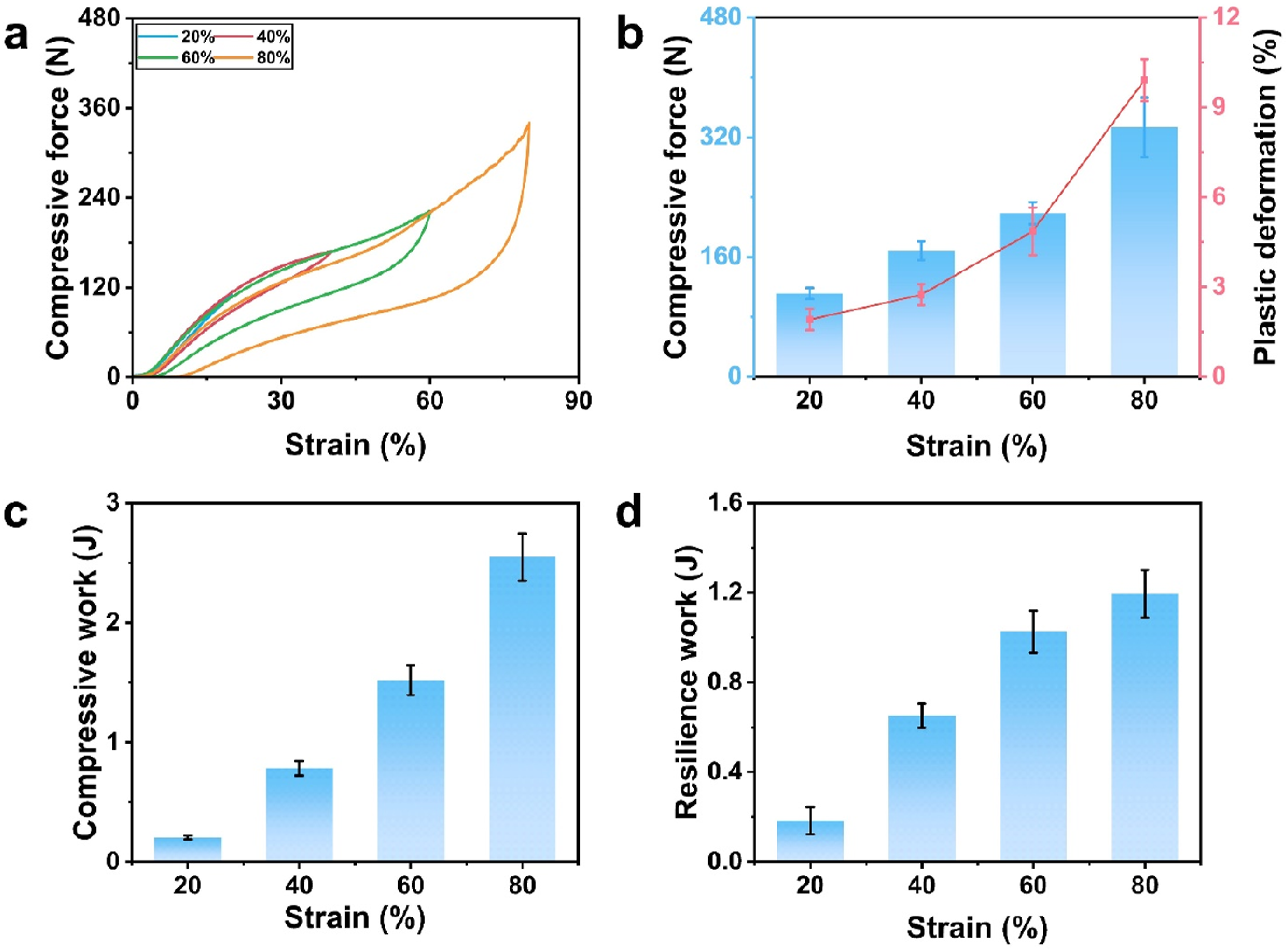
Quasi-static plate compression with 1000-cycle compression at different strains
Figure 7(a) represents the 1000-cycle compression test curve at 20%, 40%, 60%, and 80% compression strain under 10 mm/min speeds. It can be observed from Figure 7(b) that under the 1000-cycle compression test at different strains, the shape of the compression curves remains essentially consistent. But the cyclic compression process leads to an increase in the cumulative plastic deformation of the SMFs and the fabric structure, which is typically reflected as a change in the slope of the stress-strain curve. The accumulation of plastic deformation results in a reduction of the compression force. It can be seen from Figure 7(b) that as the deformation increases, the fabric’s compression force increases, and the change in compression force during the cyclic compression process is more significant. By combining Figure 7(c)–(f), it can be found that under different compressive cycles, the slope of the compression-recovery curve of the WKSF decreases, and the load-bearing performance declines. Curve of cyclic compression test. (a) compression test curve of 1000 cycles under different strains; (b) compression force under 20%, 40%, 60%, and 80% strains; (c)-(f) Cycle-1, Cycle-10, Cycle-100, and Cycle-1000 curve under 20%, 40%, 60%, and 80%, respectively.
Furthermore, from Figure 8, it can be observed that the compression work and resilience work of the WKSF decreases with the increase in the number of compression cycles. Additionally, from Figure 8, the plastic deformation of the WKSF during the process increases with the number of cycles, which further proves that as the number of cycles increases, the cumulative plastic deformation of the WKSF increases, the material undergoes fatigue phenomena, leading to a decline in the spacer’s bending performance and resilience. Consequently, under a constant strain condition, the energy absorbed and released by the fabric decreases. However, after undergoing numerous compression cycles, the WKSF’s compression performance does decrease, but the downward trend gradually flattens out, especially after approximately 100 compressions, where its performance remains largely stable. This characteristic underscores the fabric’s remarkable compressive durability. For the WKSF, this durability is crucial for maintaining its functionality over the long term, especially in applications requiring frequent use and enduring continuous loading-unloading cycles, such as furniture padding, car seats, or other mattress materials. Considering its rate of performance degradation, its initial high-performance level, and the durability standards in practical applications, the WKSF’s durability performance is undoubtedly satisfactory, even exhibiting excellence in specific application fields. Results of cyclic compression test. (a) compressive work; (b) resilience work, (c) plastic deformation.
Compression behavior of WKSF
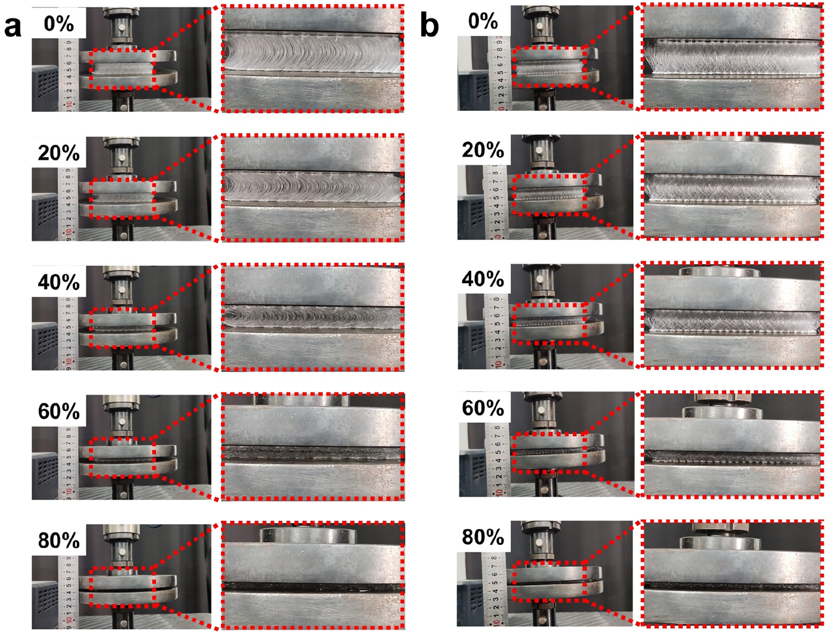
From the physical images of the compression process of WKSF in left view and front view, which is shown in Figure 9(a) and Figure 9(b), as well as the stress-strain curves, which shown in Figure 16(c), we can clearly observe that the compression process is mainly divided into the following three stages 11,17–19: I. Elastic Stage: This is the initial stage of compression, where the initial elastic modulus remains constant, following Hooke’s Law. This stage is relatively short and is mainly characterized by the small amplitude deformation of the upright SMFs in the spacer layer before instability, at which time the fabric exhibits a relatively stable compressive stiffness. II. Plateau Stage: As the compressive force gradually increases, the fabric enters the yield zone, where the compression process exhibits significant nonlinear characteristics. In this stage, the SMFs directly subjected to pressure begin to lose stability and undergo elastic bending deformation. The increase in the curvature of the bent SMFs directly leads to a significant reduction in the thickness of the fabric. At this point, a smaller external force can cause a larger deformation, and the compressive stiffness of the fabric decreases, making it relatively easier to compress, but in this process, there is initially the contact between the SMFs. III. Densification Stage: Under continued compression, the spacer layer of the fabric is further compressed until it reaches a dense state. At this point, the SMFs compression processes contact each other, and even with small deformations, the fabric will show a significant increase in strain, and the thickness will hardly decrease further. Physical images of WKSF compression process. (a) left view of WKSF; (b) front view of WKSF.
Finite element simulation results analysis
Simulation results analysis of displacement U
Figure 10 vividly displays the spatial displacement of the individual SMFs of the model in the finite element simulation results. By combining Figure 10(a)–(c), it can be observed that in the early stages of the compression simulation, that is, at a small strain of 20%, significant displacements are observed in the SMFs in two key areas: the central position and the compressed ends. This distribution of displacement suggests that at low strain levels, the central region of the SMFs is prone to deformation and displacement due to being in a state of buckling and lacking restraint, while the ends experience significant displacement due to the compressive action. As the compressive strain increases, the large displacements at the central position of the SMFs gradually decrease, and the displacements in the compressed SMFs end areas gradually increase. This phenomenon indicates that as the strain increases, the deformation mode of the SMFs shifts from the central position to the compressed ends, which may be due to the nonlinear behavior of the SMFs material and the gradual densification of the structure. From the top view (Figure 10(a) top view), it is evident that compared to the initial state, when the strain reaches 80%, the projected area of the WKSF model on the horizontal plane has increased. This increase in area is partly due to the SMFs collapsing under compression and partly because, after being compressed, the height of the SMFs decreases, and they come into contact with each other more frequently. This leads to an intensification of the intermolecular forces between the SMFs, and a gradual densification that forces the fibers in the edge areas to expand outward. This also results in stronger compressive performance of the SMFs, that is, a further increase in compressive strength. Figure 11 presents simulation results of the WKSF unit cell model extracted from the overall model from three different perspectives, and it can be found that the unit cell model has essentially the same displacement behavior pattern as the full model. Moreover, the unit cell model has an advantage when directly observing the spatial position changes of each SMFs during the compression process. Displacement U plots of finite element analysis model under different strain: (a) top view; (b) left view; (c) front view. Displacement U plots of the unit cell under different strain: (a) top view; (b) left view; (c) front view.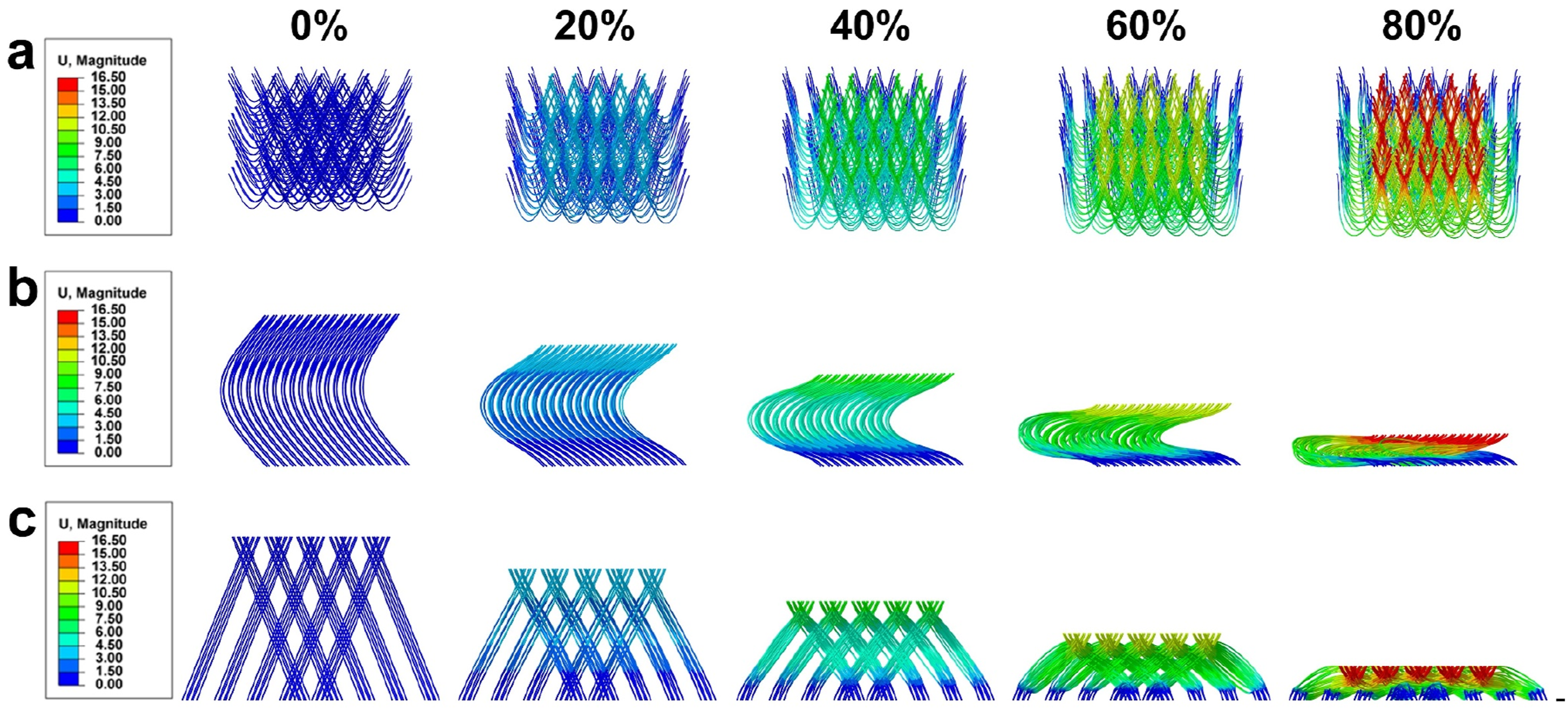

Simulation results analysis of Von Mises stress
Von Mises stress, as a key indicator for characterizing the yield behavior of materials ,
18
which show in Figure 12, plays an irreplaceable role in the study of mechanical responses of WKSF. Utilizing finite element simulation technology, by calculating the Von Mises stress, it is possible to gain an in-depth insight into the stress state of the WKSF under variable compression conditions, evaluate its compressive properties, and predict potential structural failures. This, in turn, provides a scientific basis for engineering design and material selection. Analyzing the data results, under the condition of 80% strain, the maximum Von Mises stress of the SMFs is 140.02 MPa. This finding indicates that, compared with the tensile fracture performance measurements of the SMFs, the stress level of the SMFs under compression at large deformations is low at the strain level studied. In the simulation analysis, as shown in Figure 13, whether using a full model or a unit cell model, the distribution of Von Mises stress reveals the stress concentration phenomenon of the SMFs during the compression process. These stress concentration areas are primarily located at the ends and the middle bend regions of the SMFs. Specifically, from the central bend region to the ends, the Von Mises stress exhibits a trend of initially decreasing and then increasing, a phenomenon that is consistent across different levels of strain. This regularity in stress concentration can be attributed to the combined effects of two factors. Firstly, when the SMFs are subjected to compression, their ends come into direct contact with the compression plate, where stress concentration is significant due to the action of boundary constraints. Secondly, the SMFs already possess an initial curvature, and under axial pressure, the regions with a larger curvature in the central are prone to instability, leading to greater deformation and consequently the formation of stress concentration areas. The occurrence of stress concentration can easily lead to material damage during the application process; hence it is advisable to avoid the formation of excessively large initial curvature in the SMFs during the structural design of WKSF, which is beneficial for enhancing the lifespan of the WKFSs. Von Mises stress diagram of finite element analysis model under different strains: (a) top view; (b) left view; (c) front view. Von Mises stress plots of the unit cell under different strain: (a) top view; (b) left view; (c) front view.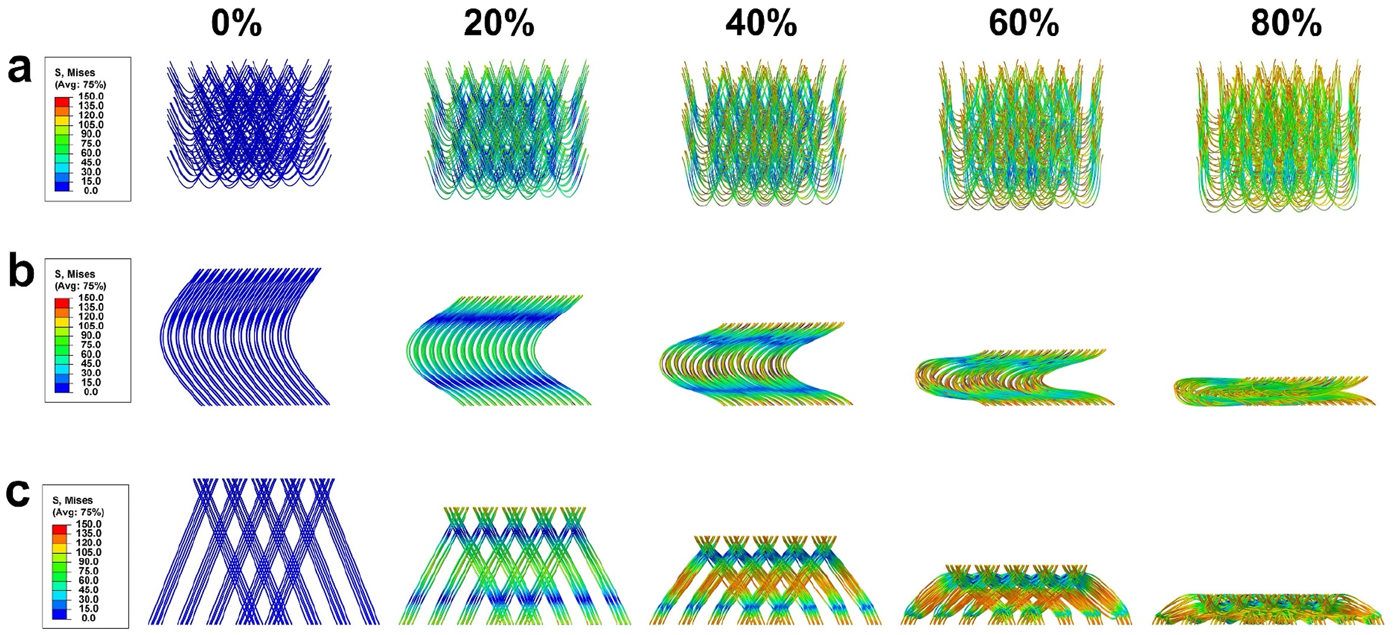

Simulation results analysis of PEEQ and SENER
In finite element simulation, the equivalent plastic strain (PEEQ) and strain energy density (SENER) are two critical metrics used to evaluate the average plastic deformation and the elastic strain energy stored per unit volume of a material during compression processes .20–22 PEEQ is utilized to measure the average plastic deformation of the material, while SENER assesses the elastic strain energy stored in a unit volume. Interestingly, during the compression of SMFs, the distribution patterns of PEEQ and SENER, which show in Figure 14(a) and (b), respectively, exhibit a resemblance to the distribution of displacement and von Mises stress, predominantly occurring at the ends and the midpoints of the SMFs. This distribution shows a trend that decreases initially and then increases from the central bend area to the fiber ends. (a) PEEQ plots of the unit cell under 80% strain; (b) SENER plots of the unit cell under 80% strain.
The formation of this distribution pattern is primarily attributed to the increase in von Mises stress as the strain in the SMFs increases, leading to significant elastic and plastic deformation in areas of stress concentration. As stress increases, the material’s ability to undergo plastic deformation is demonstrated, resulting in a rise in the PEEQ value. The von Mises stress, an indicator used to measure the yield of materials under multiaxial stress states, increases in areas of stress concentration, promoting the occurrence of plastic deformation. 23
Simultaneously, SENER, which reflects the energy stored during the elastic stage, also shows a corresponding increase in areas of stress concentration. This is because strain energy accumulates as the material undergoes elastic deformation. 23 Thus, the similar distribution patterns of PEEQ and SENER reveal the deformation mechanism of materials under compression, providing an important perspective for understanding the behavior of materials under complex loading conditions.
In the design and evaluation of structural materials, it is crucial to conduct a detailed analysis of the stress and strain states in the areas at the ends and midpoints of the spaced SMFs, as these areas of stress concentration are more likely to be the starting points of failure. 24 The distribution patterns of PEEQ and SENER revealed by finite element simulation can guide us in better understanding the deformation mechanism of materials during the compression process, thereby making more informed decisions in material design and structural optimization.
Plastic deformation analysis of fiber contact area
Based on the analysis of the compression behavior of WKSF, we can draw some key findings. When the WKSF material is subjected to compression and develops further with the plateau stage, the SMFs gradually begin to contact each other, a phenomenon that marks a new stage in the material behavior. As the compression process continues, the material enters the densification stage, when the surface contact region between the SMFs increases significantly, leading to the hardening phenomenon of the WKSF. It is worth noting that the phenomenon of SMFs contacting each other is often easily overlooked during the research process. However, this phenomenon has important implications for the overall material properties and failure mechanisms. At Figure 15(a), we can find that the region where the SMFs are in contact with each other produces a higher von Mises stress at 80% strain, which indicates the occurrence of the stress concentration phenomenon. This stress concentration may lead to localized failure of the material, thus affecting the stability of the overall structure. Also, in the contact region, we observed that the PEEQ (as shown in Figure 15(b)) and SENER (as shown in Figure 15(c)) have similar distributions. This finding suggests that a large amount of plastic deformation occurs in the contact region as the SMFs are compressed and come into contact with each other. This plastic deformation not only changes the microstructure of the material, but may also affect its macroscopic properties, such as strength and toughness. During plastic deformation, the microstructure within the material undergoes changes, such as dislocation motion, grain rotation, and stage transformation, which ultimately lead to permanent deformation of the material on a macroscopic scale. And with the increase of the number of compression cycles, the plastic deformation is intensified, which leads to the decrease of elastic properties and thickness of WKSF (as shown in Figures 7 and 8), which seriously affects the performance of WKSF. This interesting phenomenon further reveals that the generation of fabric compression failure during compression of WKSF. Fabric compression failure, defined as the deformation of spacer yarn reaching the bending limit and the spacer fabric being compressed to a Densification Stage, is evident in the sharp rise in stiffness. This process is not only limited to the central region of the SMFs and the contact region of the compression plate, but also occurs in the region where the SMFs are in contact with each other. These findings are important guidelines for understanding and improving the compression properties of WKSF materials, which will help us to design more durable and efficient WKSFs. Simulation results of plastic deformation in fiber contact area. (a), (b), and (c) Von Mises stress, PEEQ, and SENER distribution in the contact area under 80% strain.
Simulation results analysis of compression force-strain and compression work-strain
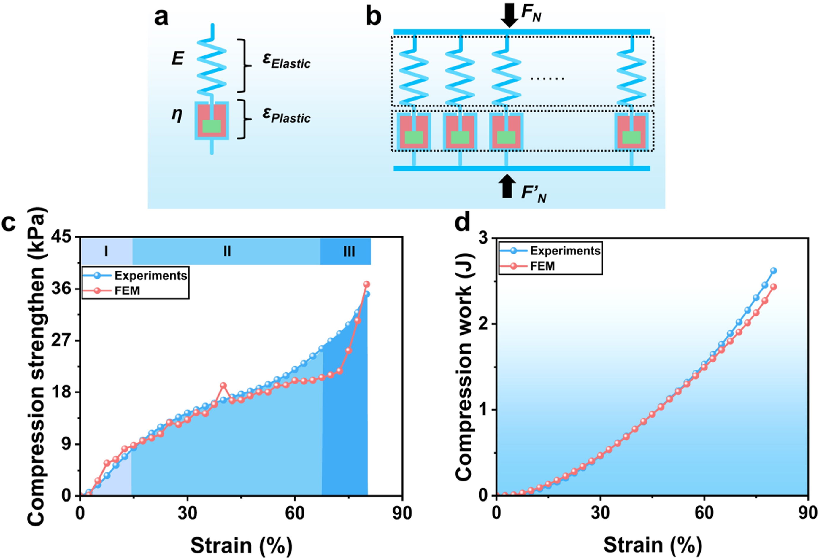
In the model assumptions of the WKSF, it can be divided into three layers, upper and lower surface layer, and spacer layer. During the compression process of WKSF, the stress is borne by the SMFs, and the stress generated by the upper and lower layers of fabric under small deformation is ignored to reduce the complexity of the model. SMFs are made of polyester, and it can be seen from the tensile fracture curve that SMFs has an obvious plastic deformation stage, so a single SMFs can be regarded as a member with both elastic and plastic. All the SMFs in the WKSF can be regarded as a set of elastic-plastic members in parallel. Therefore, according to the elastic-plastic theory, the Maxwell model as shown in Figure 16(a) is selected for the SMFs.25,26 According to the characteristics of the model, for the SMFs compression process, the total deformation (a) Maxwell model of SMFs; (b) generalized Maxwell model of WKSF; (c) compression stress-strain curve; (d) compression work-strain curve.


Because

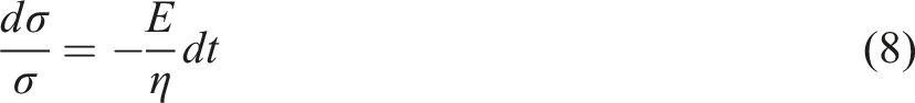
Integrate and apply in the initial condition 

The generalized Maxwell constitutive model is formed by parallel connection, which show in Figure 16(b), there is


Figure 16(c) and d presents the simulated compression strengthen-strain and compression work-strain results for the WKSF model versus the actual fabric sample performance tests. The simulation results for two different parameters exhibit similar curves to the experimental test results, indicating that the simulation reflects the three stages of compression of the WKSF. The simulation results were verified using the Pearson correlation coefficient, and the results showed that the correlation coefficients for the compression strength and compression work between the experimental and simulation results reached 0.97 and 0.99, respectively, indicating a high degree of correlation. Despite the high correlation between the simulation and test results, there is still a certain degree of error. The inconsistencies between the simulation analysis and the experimental test results are mainly caused by the following reasons. Firstly, the simplification of the WKSF during the modeling process, which lacks the top and bottom layers of the WKSF; secondly, the SMFs are controlled by the loop structure within the fabric, and during the actual compression process, there is a certain amount of horizontal movement and slippage of the loop structure. Finally, during the manufacturing process, due to the limitations of spatial positioning, the SMFs will contact each other and interact, and the local deformation and force effects caused by this contact were neglected during the modeling process.
Conclusions
In this study, we systematically investigated the compression behavior of WKSF under different compression speeds and compression strains, especially focusing on the effects of 1000 cycles of compression at various compression strains. The experimental results indicate that WKSF possesses excellent compressive properties. Utilizing the finite element method, we successfully simulated the compression process of WKSF, and the simulated results closely match the experimental results in terms of compressive force-strain and compression work-strain curves. Notably, the simulation results reveal an interesting phenomenon: under different compression strain conditions, the maximum displacement U of SMFs shifts from the central region to the compression end. Through the analysis of Von Mises stress, PEEQ, and SENER results, we found that these three factors exhibit similar distribution patterns during the simulation of WKSF compression, with the regions of maximum plastic deformation concentrated at the compressed end and intermediate inflection points of the SMFs. The simulation also suggests that the mutual contact between SMFs under compression results in significant local stress concentration and plastic deformation, a phenomenon that has been overlooked in previous research. Therefore, a detailed analysis of plastic deformation in these critical regions is particularly important in the design and evaluation of WKSF. In summary, this study not only confirms the superior compressive properties of WKSF but also reveals its complex micro-mechanisms through finite element analysis. These findings provide valuable references for the further application and optimization of WKSF.
Footnotes
Declaration of conflicting interests
The author(s) declared no potential conflicts of interest with respect to the research, authorship, and/or publication of this article.
Funding
The author(s) disclosed receipt of the following financial support for the research, authorship, and/or publication of this article: The authors acknowledge the financial support from the National Nature Science Funds of China (52373058, 11972172), the Fundamental Research Funds for the Central Universities (JUSRP62005), and a Project Funded by the Priority Academic Program Development of Jiangsu Higher Education Institutions (PAP).