
Abstract
Nowadays, applications of spacer fabric cover wider areas of technical textile. It is used in the automotive textile, personal protective clothing, sports textile, foundation garments, pads for swimwear, buffer clothing, medical textile etc. It does possess good recovery to compression, high bulk with relatively lightweight and very good moisture permeability. Almost in all applications, spacer fabrics are compressed by different parts of human body. Body parts have different shapes and curvatures. In all standard methods, spacer fabric compressibility is measured by a pair of flat circular plate which cannot represent a human body. The contour of body can be assumed as cylindrical with varying radius of curvature. So, it is necessary to understand the mechanism of compression of spacer fabric with cylindrical surface in order to understand the performance of the fabric under real-world dynamics. In this research, an effort is being made to predict the compression behaviour of warp-knitted spacer fabric by flat as well as cylindrical surface. Finite Element Models were designed on Abaqus/CAE platform to meet above requirement with variable circumstances. Experimental setup was also made to analyse cylindrical and flat compression at different circumstances. Results show that flat compression and cylindrical compression are largely deferred in terms of shape of load-deformation curve and compressional energy. Effect of variables on compression behaviour was also analysed. Model results were validated with experimental values. It is found that the proposed model has got a good agreement with the experimental results.
Keywords
Introduction
Warp-knitted spacer fabrics comprise two outer layers that are connected together but kept apart by an inner layer of spacer monofilaments [1]. Spacer fabrics possess good resilience to compression, high bulk with relatively lightweight and very good moisture permeability with thermoregulation [2, 3]. In addition, spacer fabrics are good at pressure relief [3–5]. The unique combination of these characteristics made this fabric suitable for a wide range of applications.
Nowadays, applications of spacer fabric cover wider areas, from a simple replacement of foam in bags to diversified areas of technical textiles. It is used in the areas of automobile textile (as a cushions [6] or car seats [7]), personal protective clothing (as a cushioning material [8–10]), sports textile [11], and foundation garments (functional bra support [12]), pads for swimwear [13], buffer clothing [14], medical textile (knee braces [15]), geo-textile, civil engineering, etc. However, engineering design of spacer architecture is still at its infancy.
Almost in all above applications, spacer fabrics are compressed by different parts of human body. Radius of curvature of various parts of human body changes with age and varies with gender. It also varies from one person to another person. Not only this, different parts of a human body have different shapes and curvatures. Hence, the contour of body can be assumed as cylindrical with varying radius of curvature. Many authors have described assessment of protective properties of warp-knitted spacer fabrics in hemispherical form, in order to simulate the realistic requirement of human body protection [16–18]. In all standard methods, spacer fabric compressibility is measured by a pair of circular plate which is basically a flat surface and cannot represent truly a human body in its shape. So, it is necessary to understand the mechanism of compression of spacer fabric with cylindrical surface. On the above circumstances, this paper aims to understand behaviour of warp-knitted spacer fabric under the compressive load by flat as well as cylindrical surface. An effort is also being made to predict the compression behaviour in order to understand the performance of the fabric under real-world dynamics.
Experimental details
Preparation of fabric samples
It was found that four-guide bar structures are the most popular commercial structures due to economical advantage over six-guide bar structures but hardly any research work had been done with four-guide-bar structures. Hence, all the samples in the study were produced double-needle bad Raschel knitting machine with four-guide bars. Two front guide bars (GB1 & GB2) knit a base fabric on the front needle bar and one back guide bar (GB4) knit base fabric on the back needle bar. One spacer guide bar (GB3) knits on both needle beds in succession (see Figure 1). Back needle bar structure was kept same for all of the samples. It was close lap structure with one needle space under lap.
Four-guide bars construction of spacer fabric. (a) Face fabric made of two guide bars yarn (GB1 &GB2). (b) Spacer yarn in between face and back fabric (GB3). (c) Back fabric made of back guide bar yarn (GB4).
All the samples were produced by polyester filament yarn. Multifilament yarn of 20 tex/96 f was used in both front guide bars and back guide bar. Monofilament yarns were used in the spacer guide bar. Four different surface structures namely Hexagonal mesh (H), Rhombic mesh (R), Full Tricot structure (T), Pillar with inlay structure (P) were developed at front needle bar for investigation with spacer yarn linear density 28 tex (dia 0.2 mm) (See Figure 2). Three others spacer yarn linear density 22 tex (dia 0.18 mm), 18 tex (dia 0.16 mm) and 14 tex (dia 0.14 mm) were also taken for samples preparation. Three other Hexagonal mesh (H) structures were produced by using those monofilament spacer yarns. They are identified in this paper as HD2, HD3 and HD4, respectively. Table 1 gives a summary of all structures.
Face and back fabric surface structure. (a) Rhombic Mesh (R). (b) Hexagonal Mesh (H). (c) Full Tricot (T). (d) Pillar with inlay structure (P). (e) Close lap structure with one needle space under lap. Chain notations for front and back guide bar surface structures.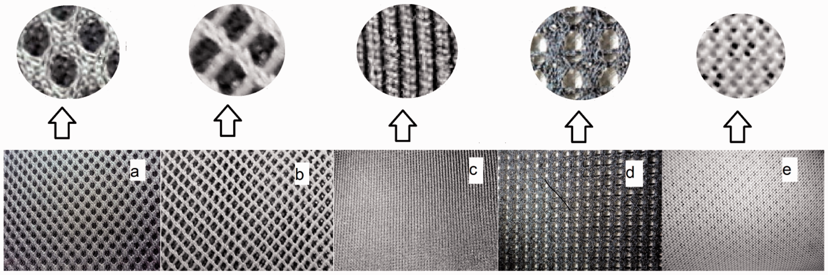

Summary of variables used for samples preparation.

Compression tests
An INSTRON 3382 device was used to measure flat plate compression with reference to the standard ASTM D575. A pair of circular plates with a diameter of 15 cm were used. The compression speed was set to 1 mm/min. The samples’ size was 10cm × 10 cm. To measure cylindrical compression, four cylinders (with diameter of 4, 6, 8 and 10 cm) made of non-compressible material were taken. Cylinders were cut vertically to get two equally divided half cylinders and one half cylinder was placed separately in between spacer fabric and upper plate. Double-sided adhesive tape was used to stick flat surface of half-cylinder with upper plate to avoid slippage during compression (see Figure 3). All compression tests were conducted to compress the material with maximum compression strain of 0.70, thereafter allowed to recover at same speed mentioned above.
Measurement of compressibility by cylindrical upper plate and flat upper plate, respectively.
Models
Finite element models were developed in Abaqus/CAE 6.12-1 platform to measure compression performance under different variable situations as per sample plan. The parts of models (see Figure 4) were designed in Solidworks platform and imported to Abaques. In Finite Element Models [FEMs], Young’s modulus, Poisson’s ratio and density of polyester yarn were taken 6773.3 MPa, 0.3 and 1.38 × 10³ kg/m3, respectively. It was assumed that upper plate, lower plate and cylinder were made of solid hard material. Young’s modulus, Poisson’s ratio and density of solid hard material were considered as 200 GPa, 0.29 and 7.872 × 10³ kg/m3, respectively [18]. Solid homogeneous sections were taken. Isotropic polyester material was considered for analysis. ‘Standard 3D Stress’ type of elements was used with an eight-node linear brick, reduced integration and hourglass control. Analysis was done in ‘General-Dynamic-Explicit’ procedure with step time of 1 s with default iterative nonlinear solver. Yarn to yarn and yarn to steel frictional coefficient was considered 0.3. Directionality of frictional properties was considered ‘isotropic’ and frictional formulation was used as ‘Penalty’ in Abaqus/CAE 6.12-1. Lower disc bottom face was pinned. Upper disc and cylinder having no displacement and rotation with respect to X- and Y-axes. Velocity of upper plate and cylinder was taken in such a way to compressed and allowed to recover 70%.
Parts of FEMs were developed in Abaqus/CAE 6.12-1 platform. (a) Cylindrical compression. (b) Flat compression.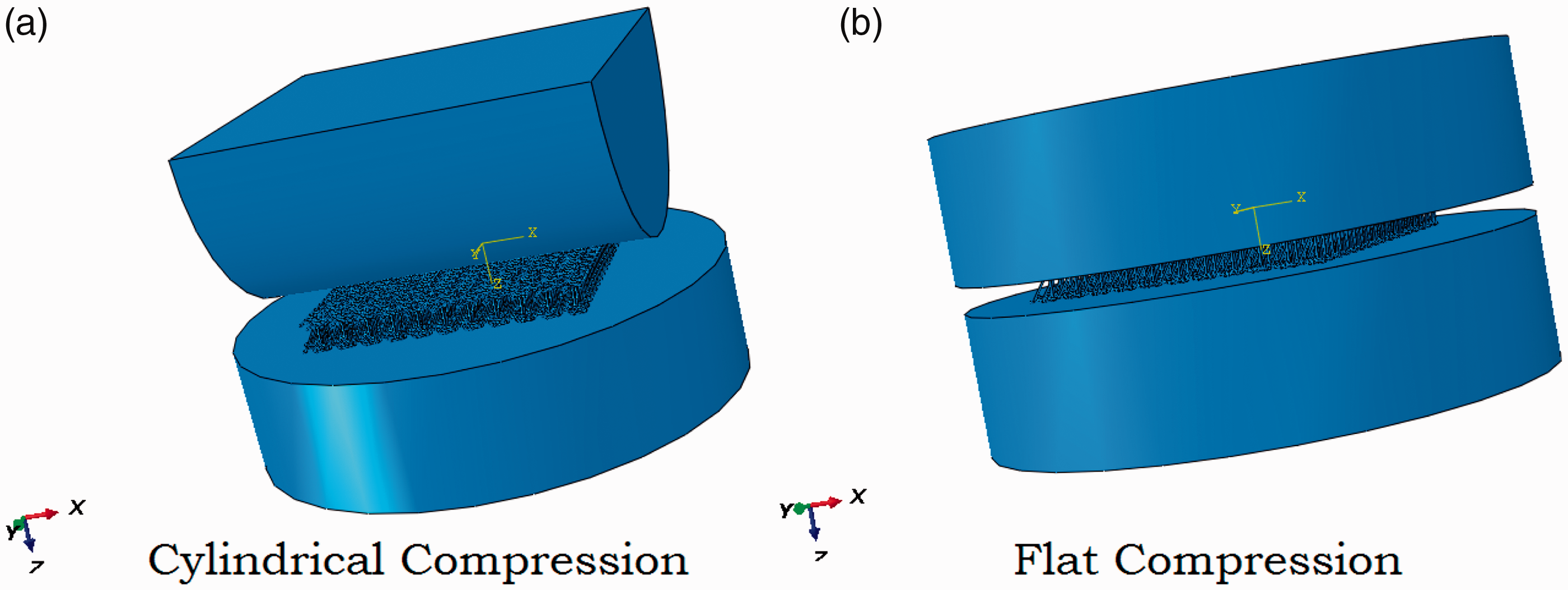
Results and discussion
Compression and recovery characteristics
Spacer fabric samples were compressed and allowed to recover by two different methods. First method was flat compression, where it was compressed and allowed to recover by upper flat disc of Instron device. Second method was cylindrical compression, where it was compressed and allowed to recover by a cylinder by keeping cylinder at bottom of upper disc of Instron device. Finite element models were also designed to meet above situation of experimental environment. Contours of von Mises stress developed in FEM are computed at an element levels. Those images help us to understand magnitude of stress develop on different regions of spacer fabric during dynamic compression and recovery activity. For clear understanding, only a small portion of spacer yarn is shown (see Figure 5). It is observed that higher stress is concentrated at centre of vertical parts of spacer yarn, which causes recovery at removal of deforming forces.
Von Mises stress distribution on elements of spacer yarn during compression. (a) At 70% compression of spacer yarn structure. (b) At 10% compression of spacer loops. (c) At 50% compression of spacer loops. (d) At 70% compression of spacer loops.
Flat and cylindrical compression and recovery curves obtained from the model and experiment of Hexagonal mesh fabric (Sample code H) are shown in Figure 6. (Other samples having similar trend are not shown in this figure.) It is observed from figures that load-deformation behaviour of spacer fabric under compression by flat surface and cylindrical surface largely differ. The difference is clearly depicted from all the figures (see Figures 6–10) of load-deformation curves. In flat compression, spacer fabric is compressed uniformly by its whole flat surface. Shape of curves obtained during compression by flat surface can be divided in three sections (see Figure 6).
Compression and recovery curves. Effect of radius of curvature of cylinder on load-deformation curve. Effect of linear density (diameter) of monofilament on load-deformation curve for flat and cylindrical compression. (a) Flat compression. (b) Cylindrical compression. Effect of spacer fabric thickness on load-deformation curves for flat and cylindrical compression. (a) Flat compression. (b) Cylindrical compression. Effect of spacer fabric surface structure on load-deformation curves for flat and cylindrical compression. (a) Flat compression. (b) Cylindrical compression.

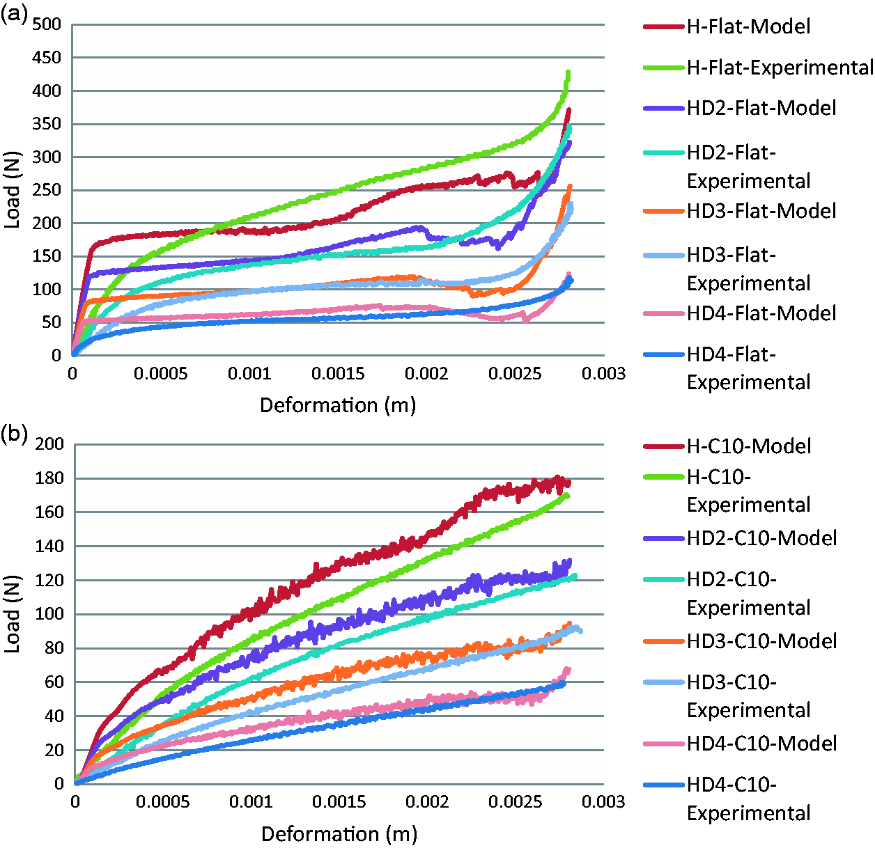

In first section, load increases suddenly on contact. At contact, monofilament yarns resist downward movement of upper surface. Hence, load increases sharply till bending of monofilaments starts. In second section, load increases very slowly as bended monofilaments cannot resist downward movement. In this section, fabric is compressed and free space present in the structure of fabric reduces gradually. In third section, again load increases sharply as free space almost removed in earlier stage. The shape of the recovery curves is almost similar to the compression curves but in reverse direction and lagged behind the compression curves. At start of recovery, load decreases suddenly, thereafter decreases gradually and finally recovers fully.
However, in case of cylindrical compression, no such clearly distinguishing section is observed. Load gradually increases with deformation. Rate of increment of load with deformation is lower than that of flat compression. In flat compression, whole upper surface of fabric is compressed at a time, whereas cylindrical compression starts from a line. Gradually it spreads towards front and back side of that line. Initially, bending of monofilament starts from that contact line; thereafter, it spreads to its back and front side. Shape of recovery curve is almost similar to compression curve from reverse direction and recovery curve lagged behind the compression curve.
Effect of radius of curvature of cylinder
Four cylinders with different diameters 4, 6, 8 and 10 cm were taken for experiment. Similarly, FE models were also designed to replicate experimental conditions. In Figure 7, the cylinder denoted as C4, C6, C8 and C10, having diameter of 4, 6, 8 and 10 cm, respectively. Flat surface may be considered as cylinder of infinite diameter that is also considered for comparison.
It is observed from experiment and from FEM that load increases up to 428.61 and 371.35 N, respectively, at 70% deformation for flat compression of Hexagonal Mesh (see Figure 7). Similar values for cylindrical compression with 10 cm diameter cylinder (C10) were only169.41 and 177.86 N, respectively. The values reduce with reducing diameter of cylinder. As cylinder moves downward, bending of monofilaments takes place. Rate at which monofilament yarns bend depends on diameter of cylinder. That finally determines the rate of increase of load in load-deformation curve.
Effect of linear density of spacer yarn
Linear density of monofilament spacer yarn is one of the important factors of compressibility of spacer fabric. Four different linear densities of monofilament were taken for sample preparation. Flat and cylindrical (by C10) compressibility were measured and similar finite element models were also designed to replicate experimental condition. Effect of linear density (diameter) of monofilament on load-deformation curve is shown in Figure 8. It is observed that coarser diameter of monofilaments leads to higher load at same deformation. With increase in diameter of monofilament, it is observed that bending rigidity of filament increases that leads to increase slope of load-deformation curve (see Figure 8). Above effect is observed for flat as well as cylindrical compression for both experimental- and model-based load-deformation curves.
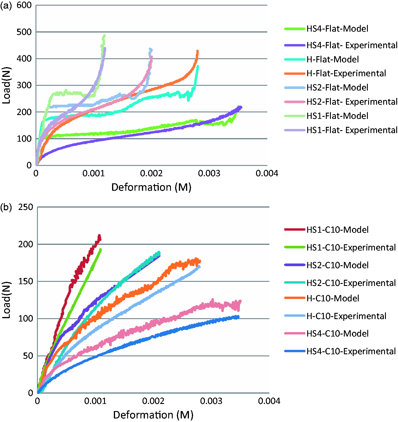
Effect of fabric thickness
The effect of fabric thickness on load-deformation curve is shown in Figure 9. It is observed that load required to deform thicker fabric (HS4) is lesser than that of thinner fabric (HS1) at same percentage of deformation. The trend is similar for both flat and cylindrical compression though in cylindrical compression fabric deform at lower deforming force. Spacer fabrics having higher thickness have longer length of monofilaments. Long monofilaments can easily bend than shorter ones. Hence, low-thickness fabric has more load bearing capability than thicker spacer fabric. It is also observed that load for cylindrical compression is always lower than flat compression.
Effect of fabric structure
Load-deformation curve also depends on surface structure of spacer fabric. That is depicted from Figure 10. Four different structures were taken under study. It is found that Tricot structure, which is most compact surface structure (visual appreance), shows higher load (Model 557.52 N, Exp 528.37 N) at 70% deformation, whereas other structures, comparatively open structures (visual appreance), show lower load than Tricot structure at 70% deformation value. Though flat and cylindrical compression have shown similar trend but effect is less prominent in case of cylindrical compression (see Figure 10). Load bearing capability of any material depends on its compactness of structure. Tricot structure is more compact structure, hence it is deformed at higher load, where as other structures require lower deformative force.
Error of prediction of load-deformation curve

Percentage of error of prediction of load-deformation curve in between model and experimental results.

Compressional energy
Compressional energy is the energy required to compress fabric. It is the area under load-deformation curve. Compressional energies are calculated from FEM and experiment with all variable circumstances is shown in Figure 11. It depends on radius of curvature of cylinder (see Figure 11(a)). Higher the radius of curvature more the energy required to compress the material, because more area is compressed with it. Flat surface is a cylinder of infinite radius, hence flat compressional energy is higher than that of cylindrical compression. The effect of linear density of spacer yarn on compressional energy is shown in Figure 11(b). It is observed that spacer fabric with finer spacer yarn requires lower energy to compression. Finer linear density of monofilament yarn having lower bending rigidity than that of coarser one, easily bends at low load. Hence, lower energy is required to compress material. Compressional energy also depends on thickness of spacer fabric (see Figure 11(c)). It is found that compressional energy increases with increase in thickness up to 4 mm after that it decreases. It is known that Energy = Force × Distance. It is already discussed in previous sections that force required to compress lower thickness fabric is more at similar percentage of deformation, whereas distance required to compressing at 70% deformation is less than that of high-thickness fabric. Hence, above effect is the result of combined effect of force and distance. Effect of structure is shown in Figure 11(d). It is observed that four different structures under study have almost same compressional energy with minute deviation. Hence, no conclusion can be drawn regarding effect of structure.
(a) Effect of radius of curvature on compressional energy, (b) effect of linear density (diameter) of monofilament on compressional energy for flat and cylindrical compression, (c) effect of spacer fabric thickness on compressional energy for flat and cylindrical compression, (d) effect of spacer fabric surface structure on compressional energy for flat and cylindrical compression.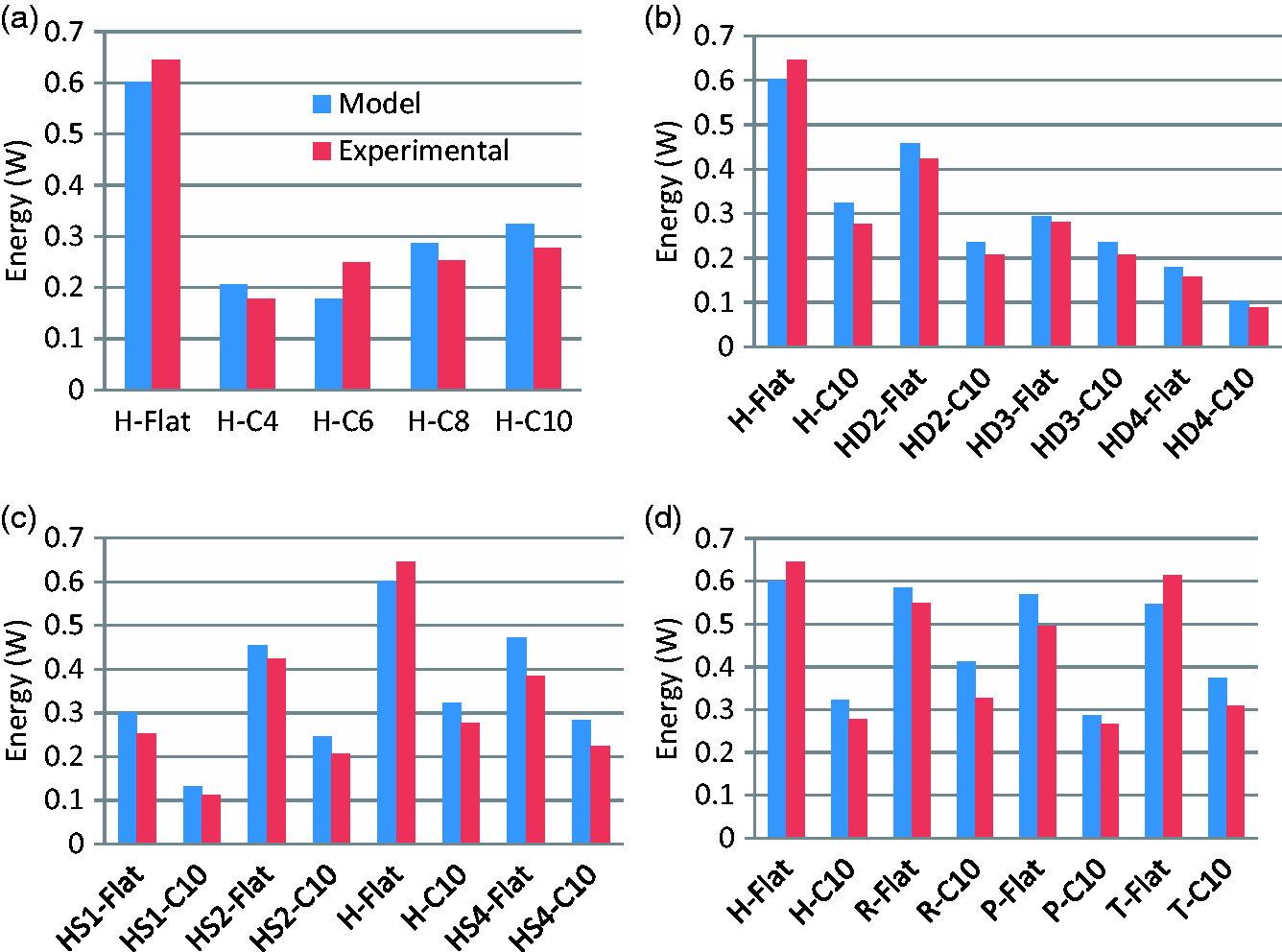
Error of prediction compressional energy

Percentage of error of prediction compressional energy in between model and experimental results.

Conclusion
It may be concluded from above discussion that results obtained from FEM are comparable with experimental results with certain percentage of acceptable error. Load-deformation curves and results of compressional energy, obtained from FEM-based and experimental-based, have shown similar trend with an average error percentage of 26.79 and 13.48, respectively. Flat compressibility and cylindrical compressibility behaviour of spacer fabrics differ to a certain extent. Behaviour of spacer fabrics compressibility depends on radius of curvature of cylinder. In case of higher radius of curvature, more reaction force is obtained from similar level of deformation percentage. Hence, compressional energy also becomes higher for higher radius of curvature. Compressibility properties also depend on linear density of spacer yarn. Finer denier yarn gives low reaction force than coarser denier. Thickness plays an important role on compressibility behaviour of spacer fabric. It is observed, under above study, that 4 mm fabric gives maximum reaction force at 70% deformation. Initially, reaction force increases with increase in thickness, thereafter, decreases at a certain level of deformation percentage. Structure has certain influence on compressibility behaviour of fabric. Different structures may have different compressibility behaviours.
Footnotes
Declaration of conflicting interests
The author(s) declared no potential conflicts of interest with respect to the research, authorship, and/or publication of this article.
Funding
The author(s) received no financial support for the research, authorship and/or publication of this article.